Crutchfield 000MVGUIDE User manual
2Replacement Headrest Monitors
3Headrest Mounted Monitors
4Overhead Monitors
5Overhead Monitors with DVD
6Wire Routing
7Wiring Connections
Inside...
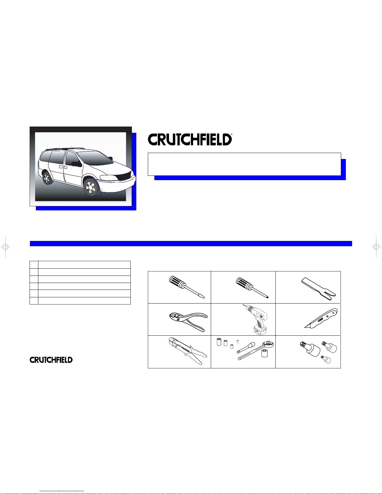
Tools Needed: (depending upon vehicle)
000MVGUIDE
Revision 04/29/04
▲
Page
*000MVGuide*
®
Copyright 2004 Crutchfield Corporation
Mobile Video Installation Guide
This installation guide offers examples of mobile video system types and suggested layouts.
The installation of your system will depend upon the make and body style of your vehicle as
well as the equipment purchased.
Flat Blade
Screwdriver Phillips
Screwdriver Panel Tool
Pliers Drill & Bit Set Utility Knife
Wire Stripper/
Crimp Tool Torx Driver Set
Socket &
Ratchet Set

MVGUIDE
Replacement Headrest Monitors
2
®
Copyright 2004 Crutchfield Corporation
The components of your mobile video system include a DVD player
(or VCR), a video monitor and a sound component (usually wireless
headphones). The optional Crutchfield wiring kit (available Fall 2004)
has all the parts you’ll need to power these components.
System Layout
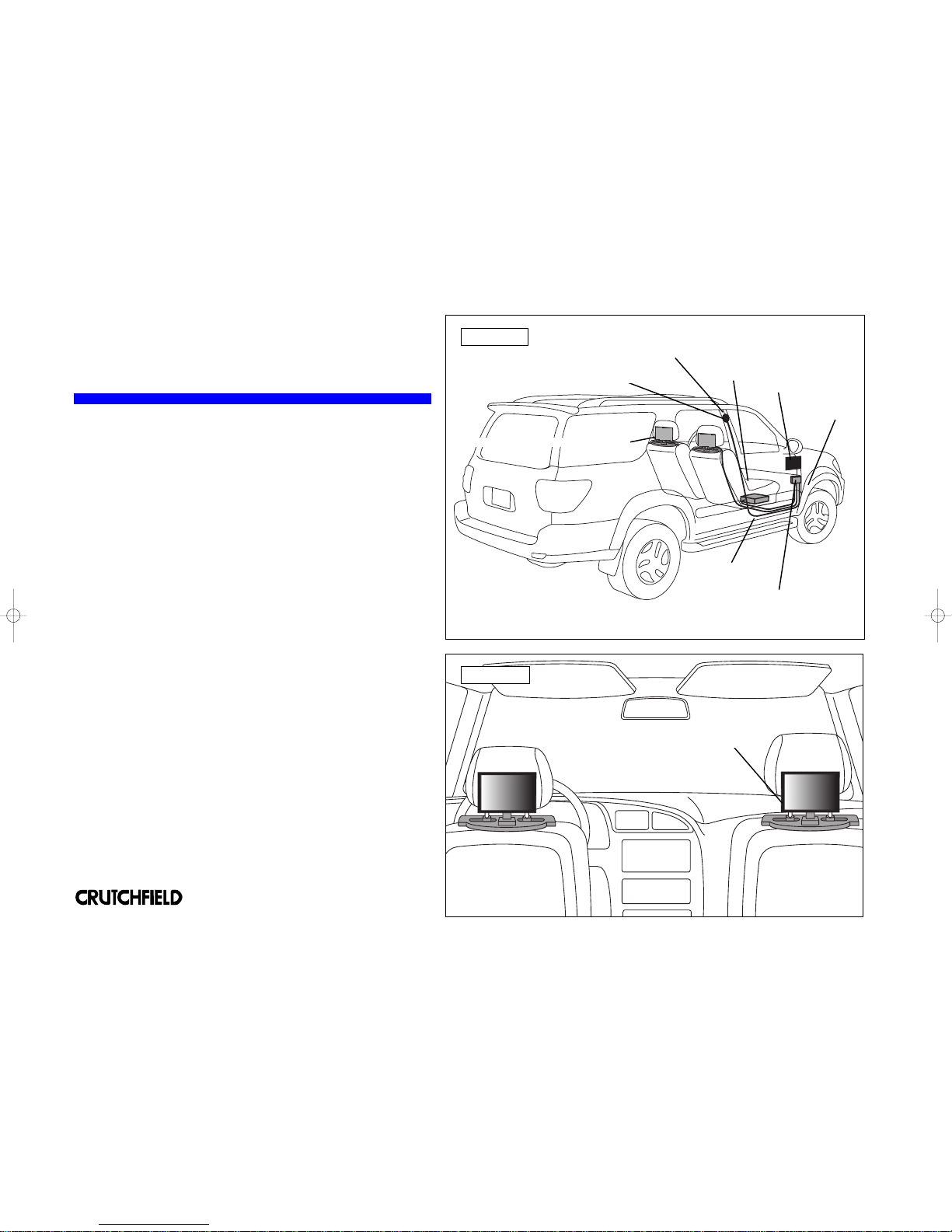
A system using replacement headrest monitors is shown with
suggested locations for components and wire routing (Figure 1).
Examine your vehicle to determine the best mounting locations.
Mounting Components
Replacement headrest monitors fit into the same slots in top of the
seat that hold the factory headrests. The wiring is fed through the seat,
to the the floor and routed to the terminal block (Figure 2). Depending
upon the vehicle, the DVD (or VCR) might be mounted under the seat,
under the dash or in the console area. Use the instructions and
hardware supplied with each component to secure them in the desired
locations.
Wire Routing
All system wiring should be concealed for safety and to give your
installation a nice finished look. Wires should be secured so that they
do not interfere with safe vehicle operation. Depending upon the
vehicle, the wiring for your system may need to be run under the dash,
door scuff plate, pillar trimpanel, kickpanel, or headliner. See page 6
for details showing how these trimpanels are typically removed. It will
be necessary to run a power wire to the main fuse panel of the vehicle
(see page 7).
Wiring Connections
The optional Crutchfield wiring kit (available Fall 2004) contains a main
power wire, ground wire, terminal blocks and other accessories for a
making power connections to your vehicle. See a full layout of compo-
nents on page 7.
FIGURE 1
Kickpanel
Replacement Headrest Monitors
Scuff Plate
DVD Player
Power Terminal
Wireless Headphone Transmitter
FIGURE 2
The monitor wiring runs
through the seat to the floor.
Fuse Panel
(location depends
upon vehicle)
Pillar Trimpanel
MVGUIDE
Headrest-Mounted Monitors
3
®
Copyright 2004 Crutchfield Corporation
The components of your mobile video system include a DVD player
(or VCR), a video monitor and a sound component (usually wireless
headphones). The optional Crutchfield wiring kit (available Fall 2004)
has all the parts you’ll need to power these components.
System Layout
A system using bracket-mounted headrest monitors is shown with
suggested locations for components and wire routing (Figure 1).
Examine your vehicle to determine the best mounting locations.
Mounting Components
Bracket-mounted headrest monitors secure to most two-post factory
headrests. You simply remove the headrest, side the monitor mounting
bracket through the posts and reinstall the headrest (Figure 2).
Depending upon the vehicle, the DVD (or VCR) might be mounted
under the seat, under the dash or in the console area. Use the
instructions and hardware supplied with each component to secure
them in the desired locations.
Wire Routing
All system wiring should be concealed for safety and to give your
installation a nice finished look. Wires should be secured so that they
do not interfere with safe vehicle operation. Depending upon the
vehicle, the wiring for your system may need to be run under the dash,
door scuff plate, pillar trimpanel, kickpanel, or headliner. See page 6
for details showing how these trimpanels are typically removed. It will
be necessary to run a power wire to the main fuse panel of the vehicle
(see page 7).
Wiring Connections
The optional Crutchfield wiring kit (available Fall 2004) contains a main
power wire, ground wire, terminal blocks and other accessories for a
making power connections to your vehicle. See a full layout of compo-
nents on page 7.
FIGURE 1
Kickpanel
Bracket Mounted Headrest Monitors
Scuff Plate
DVD Player
Power Terminal
Wireless Headphone Transmitter
FIGURE 2
Pillar Trimpanel
Fuse Panel
(location depends
upon vehicle)
The monitor mounts to the headrest posts
The components of your mobile video system include a DVD player
(or VCR), a video monitor and a sound component (usually wireless
headphones). The optional Crutchfield wiring kit (available Fall 2004)
has all the parts you’ll need to power these components.
System Layout
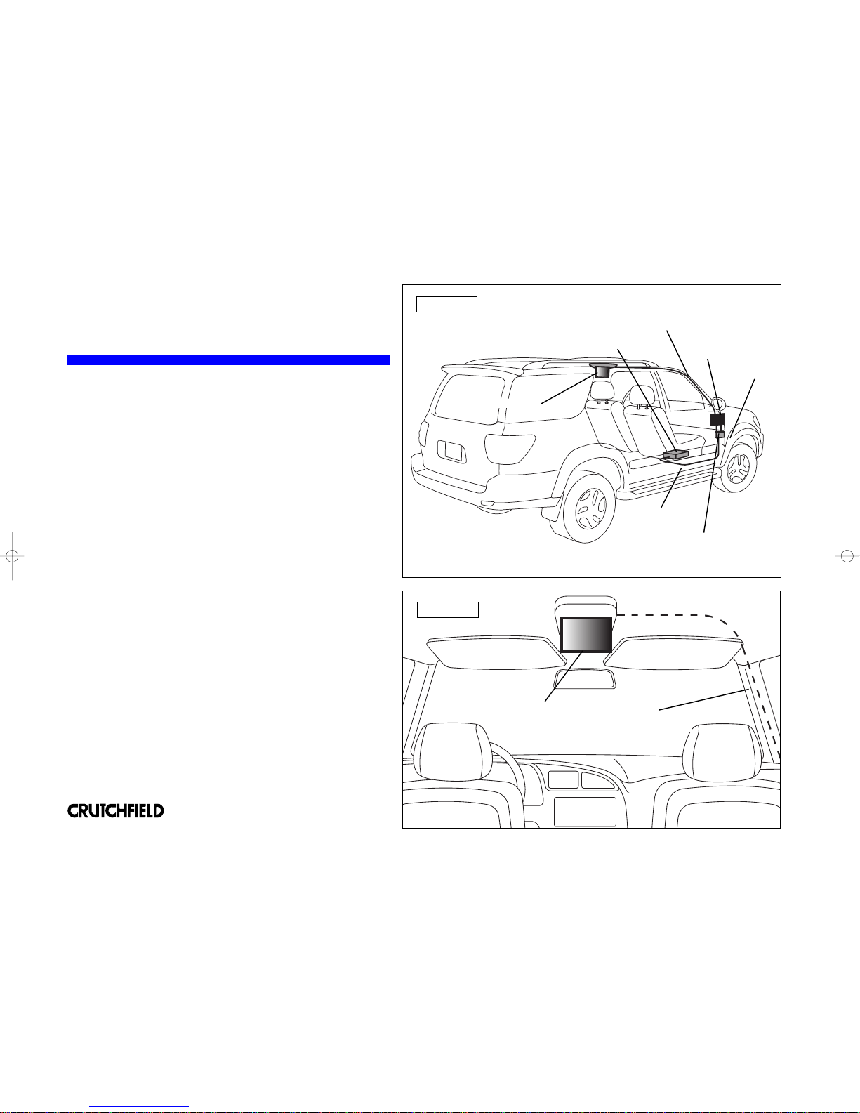
A system using an overhead monitor is shown with suggested locations
for components and wire routing (Figure 1). Examine your vehicle to
determine the best mounting locations.
Mounting Components
An overhead monitor secures to the center ceiling. Be sure it is
located for easy viewing by rear passengers (Figure 2). Use the
instructions and hardware supplied with each component to secure
them in the desired locations.
Wire Routing
All system wiring should be concealed for safety and to give your
installation a nice finished look. Wires should be secured so that they
do not interfere with safe vehicle operation. Depending upon the
vehicle, the wiring for your system may need to be run under the dash,
door scuff plate, pillar trimpanel, kickpanel, or headliner. See page 6
for details showing how these trimpanels are typically removed. It will
be necessary to run a power wire to the main fuse panel of the vehicle
(see page 7).
Wiring Connections
The optional Crutchfield wiring kit (available Fall 2004) contains a main
power wire, ground wire, terminal blocks and other accessories for a
making power connections to your vehicle. See a full layout of compo-
nents on page 7.
MVGUIDE
Overhead Monitors
4
®
Copyright 2004 Crutchfield Corporation
FIGURE 1
Kickpanel
Overhead Monitor
Scuff Plate
DVD Player
Power Terminal
Pillar Trimpanel
FIGURE 2
Overhead Monitor with wiring routed
behind Headliner and down PillarTrimpanel
Fuse Panel
(location depends
upon vehicle)

MVGUIDE
Monitor & Built-in DVD Player
5
®
Copyright 2004 Crutchfield Corporation
The components of your mobile video system include a DVD player
(or VCR), a video monitor and a sound component (usually wireless
headphones).The optional Crutchfield wiring kit (available Fall 2004)
has all the parts you’ll need to power these components.
System Layout
A system using an overhead monitor with built-in DVD player is shown
with suggested locations for components and wire routing (Figure 1).
Examine your vehicle to determine the best mounting locations.
Mounting Components
The overhead monitor secures to the center ceiling. Be sure it is
located for easy viewing by rear passengers (Figure 2). Use the
instructions and hardware supplied with each component to secure
them in the desired locations.
Wire Routing
All system wiring should be concealed for safety and to give your
installation a nice finished look. Wires should be secured so that they
do not interfere with safe vehicle operation. Depending upon the
vehicle, the wiring for your system may need to be run under the dash,
door scuff plate, pillar trimpanel, kickpanel, or headliner. See page 6
for details showing how these trimpanels are typically removed. It will
be necessary to run a power wire to the main fuse panel of the vehicle
(see page 7).
Wiring Connections
The optional Crutchfield wiring kit (available Fall 2004) contains a main
power wire, ground wire, terminal blocks and other accessories for a
making power connections to your vehicle. See a full layout of compo-
nents on page 7.
FIGURE 1
Kickpanel
Overhead Monitor
with Built-in DVD Player
Fuse Panel
(location depends
upon vehicle)
Power Terminal
FIGURE 2
Pillar Trimpanel
Overhead Monitor with wiring routed
behind Headliner and down PillarTrimpanel
MVGUIDE
Wire Routing
6
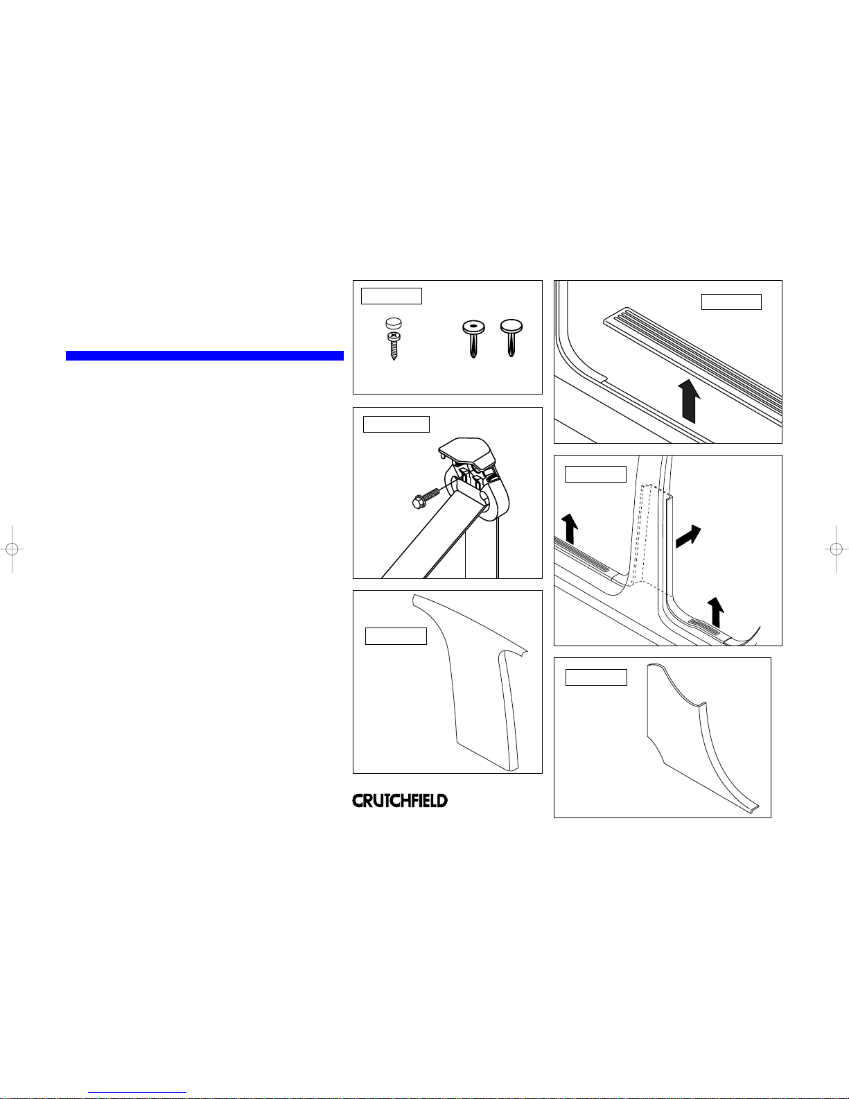
Upper Pillar Trimpanel
Lower Pillar Trimpanel
Seat Belt Cover/Anchor
Door Scuff Plate
Door Scuff Plate removal
The plates are usually removed by prying up the edges to
release clips. Some vehicles will have screws present which
will need to be removed (Figure 2).
Seat Belt removal
A seat belt may be located on the panel that needs to be
removed. Most seat belt anchor covers pry off. The seat belt
anchor is secured with a large nut or bolt (Figure 3).
Pillar Trimpanel removal
Remove seat belt if present. Remove screw covers, screws
and plastic retaining clips, if present. Pry up edges of panel
to remove (Figures 4 & 5).
Kickpanel removal
Look for screws and pry-out retaining clips to remove.
Pry out edges of panel to release and remove (Figure 6).
Routing wire behind dash
Route wire behind dash and secure with plastic wire ties.
Be sure that wire does not interfere with any moving parts to
ensure safe operation of vehicle.
Routing wire for components and power connections
Determine desired locations for each component. Use the
most direct route for wires. Remove panels necessary to
route and conceal wires. Test system before reinstalling
panels.
Kickpanel
FIGURE 2
FIGURE 1
FIGURE 3
The wire routing and concealment depends upon your vehicle
and where the components of your system are placed. The
instructions below address, in general, what panels may need
to be removed and how they typically come off. Often panels
can be pried up at edges. Screws and retaining clips might
also be present that require removal (Figure 1). To prevent
damage, always use care when removing panels.
FIGURE 4
FIGURE 5
FIGURE 6
Screw w/ Cover Retaining Clips
The seat belt is
usually secured
with a large hex
head or Torx bolt.
®
Copyright 2004 Crutchfield Corporation

MVGUIDE
Wiring Connections
7
®
Copyright 2004 Crutchfield Corporation
Monitor
Wireless Headphone
Transmitter
DVD Player
Ground Terminal Block
Power Terminal Block
Vehicle Fuse Panel
12V Constant Power
12V Switched Power
The optional Crutchfield wiring kit (available Fall 2004) contains all the parts and hardware necessary to get power to your system. Follow the
instructions supplied with the kit for details to make connections.This illustration is a generic example of a layout of components in a typical
system.
Table of contents
Other Crutchfield Car Video System manuals


Popular Car Video System manuals by other brands


Rosco
Rosco Vision System Safe-T-Scope STSK5065 Installation & user manual

Lippert Components
Lippert Components Touch Audio Elite owner's manual

CASKA
CASKA CA109-R quick start guide

Watchguard
Watchguard 4RE installation instructions

Hyundai
Hyundai ADB41D3AN user manual

Pyle
Pyle PYLE View Series PLVSMN6 Specifications