FireFinderLiquid Crystal Display Repeater
4
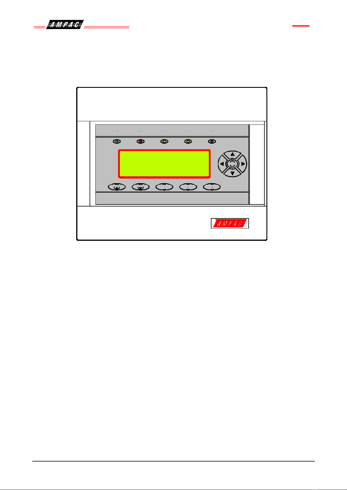
2.3 The Main Menu
Figure 4: The Main Menu
Press the forward, back, up or down keys to navigate the cursor or highlighted selection to the required
menu. In the MENU the user can view;
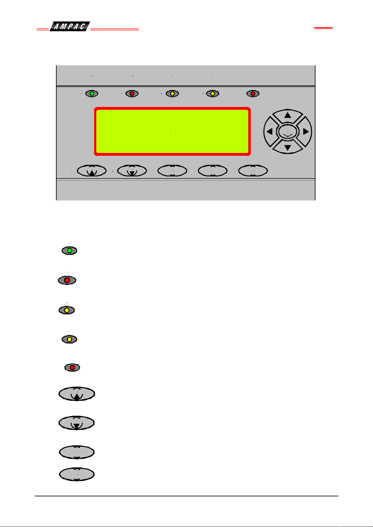
0FIRE ALARMS:
1PRE-ALARMS:
2SYSTEM STATUS:
Press Menu to enter the STATUS MENU.
Figure 5: The Status Menu
From the STATUS MENU the status of all of the system components and settings listed below can be
displayed.
3FAULTS: Pressing Menu brings up a sub-menu from which a more detailed description of
the Defect can be displayed. With a Defect present use the navigation keys to select the required field
then press menu to select the field ( 0 to 4 ).
‹Zones
Devices Œ
Loops •
Modules ŽPower
Supply •
Brigade
‹Zones Devices: Display identified zone and device faults
ŒLoops:Display identified loop faults
•Modules: Display loop and I/O module faults.
ŽSupply: This menu item will display the charger voltage, whether or not the power
supply is in fault, if the battery is correctly fitted and if Mains power is present.
•Brigade: This displaysthe fault status of all of the monitored outputs on the Brigade
Board. Eg. Bell, Aux, DSW, Warn, Fault, Alarm, Isol, Bfail, Vmon & Brigade Status.
4ISOLATES:Selecting ( pressing Menu )on the system.
5PRINTER RESET: Selecting ( pressing Menu ) resets the printer ( empties the buffer ).
6RETURN: Selecting ( pressing Menu ) returns the user to the Default screen.
0: ALARMS 1 :PRE-ALARM 2: SYS-STATUS 3: FAULTS
4: ISOLATES 5: PRINTER RESET 5 :RETURN
SELECT No.
AL:1S ALM: 000 PALM: 000 FLT: 000 ISOL: 000
0: ALARMS 0000 1 :PRE-ALARMS 0000 2:ISOLATES 0000
3: DEVICE FAULTS 0000 4:MODFAULTS 00
5: LOOP FAULTS VERSION: NZS4512
AL:1S ALM: 000 PALM: 000 FLT: 000 ISOL: 000