Crysalli CP2000-R-UC-BH User manual
1
CP2000-R-UC-BH Installation Guide
Sparkling & Still Chilled Undercounter System
CP2000-R-UC-BH undercounter chiller
With CBR or LIT Series Draft tower.
REV_1018
www.Crysalli.com
2
Start-up Sequence:
• Turn Water on to unit (conrm ow from faucets)
• Plug unit in and toggle On/O switch to the On posion.
• Turn CO2 on at tank. (carb tank may need to be bled)
• Review system operaon & maintenance w/ customer
Water Filters, CR-14FC and CR-14FCP
• Water On. Filters ushed via the ush valve and owing water.
• Water pressure thought lter system above 50 psi and not dropping o.
• 50PSI water pressure reducer valve installed in the correct direcon and aer the water lter system.
• All connecons leak free.
CO2
• CO2 hose from unit: are nut connecon on end of CO2 Hose ght to CR-3741 CO2 Regulator
(Be sure to use nylon washer supplied with Reg in ng).
• CO2 Reg connected to CO2 tank (card board/plasc washer used) ght and leak free.
• CO2 Tank Full, Completely Opened and Set to 75 PSI.
CBR tower:
• Faucets ght to shank and posioned vercally. Free of leaks. Customer has faucet wrench and
instructed how to us it.
• Handles are screwed down ght, front facing and on the appropriate faucet.
• Sparkling water; cold, carbonated and tastes clean and pure. (Run a few liters of water; is carb pump
cycling on and ow consistent without gassing out).
• Sll Water: cold and consistent ow. Tastes clean and pure.
• Flow adjustment on faucets set and knob ghtened down so ow rate appropriate and locked in.
• Connecons to tower made using supplied Superseal JG ngs from kit and leak free.
• All exposed Hoses and Fings all wrapped in insulated foam tape.
Remote Chiller: Unit on.
• Unit On and Plugged into a dedicated 120V outlet.
• Cabinet properly venlated to handle BTU load of unit heat. Can fresh air draw in and hot air vent out.
Unit free of obstrucons around it and can vent.
• If using CR-TFB1 fan box, conrm it is in place, plugged in and cycling on and o at 90 degrees.
• Rear outlet connecons for trunkline (hoses and ngs) to tower wrapped in insulted tape and leak free.
• Water Inlet connecon to unit leak free and not pinched o anywhere
• Water Bath lled with non ltered water up to the top of the white stand pipe.
Notes and Signature:
Register unit

3
1: Select a counter location for your Draft Tower and an undercounter location for the CP2000 Chiller
making sure they are within 6’ of each other (unit requires ventilation inside space it is being
placed and clearance around it). Place the CP2000 unit within 6” of the water filter connection,
floor sink & dedicated 120-volt electrical outlet (non-GFI preferred).
2: Locate the CR-KIT-CPUC Install Fitting Kit, the CR-14FC Water filter system, the CBR draft tower,
RDP drain pan and CR-3741 CO2 regulator. Take care to not lose or misplace any of the fittings
from the kits. When opening the box for the CBR draft tower, note that the Faucets, faucet
handles, faucet wrench and several fittings specifically for the draft tower ship loose with tower.
See Page 5 for Install kit items and page 7 for draft tower kit.
3: Prepare the counter for mounting the drain pan and draft tower per the cutout and hole dimesons
of the models used. Set the drain pan in place and silicone seal it to the counter. Mount the tower
and secure the superseal fitting to the product tubes on the tower.
See pages 5, 6 & 7 for fitting info, drain pan cut out and mounting the tower.
4: Locate the 6’ of CR-4L14 insulated trunkline supplied with the CR-KIT-CPUC Install kit and prep
both ends by trimming the tubes and adding the appropriate fittings for connections to the chiller
and tower. See pages 8 for tower side and 13 for chiller side trunkline prep.
5: Connect the tower and chiller. Both of these connection ends should be wrapped with the insulated
foam tape completely covering all exposed hoses and fittings, to prevent sweating and heat loss
and damage to the fittings. See pages 8 and 13 for connection info.
6: Apply the fittings to the Water Filter System, and mount it vertically in an accessible location.
Locate and attached the 50 psi water pressure reducing valve on the outlet side plumbing of the
filter system. See page 11 for filter system detail.
7: Unwrap the hoses and electrical cord coming out of the chiller. Make water inlet and CO2 inlet
connections. Route over flow drain to floor sink. Run Electrical cord to plug. See pages 12 and 14.
8: Fill the Water Bath: Remove lid and fill water bath with non-filtered tap water, fill up no less than
¼” to top of white standpipe or until the water coil is completely covered. This is the vertical white
tube in the water bath that is connected to the clear overflow hose.
9: Turn on the Water. Check connections for leaks and flush the water filters.
10: Open CO2 by turning knob on tank. Adjust regulator to 75 PSI. And check for leaks.
11: Wrap all the exposed fittings, product lines and recirculation lines the chiller side and tower side
with the insulated tape provided. This will insulate them to stay cold and prevent condensation on
the lines.
12: Plug unit power cord into 120-volt outlet. Toggle the ON/OFF rocker switch to the ON position.
Fan and compressor will turn on. Fan and compressor will automatically turn off when a complete
ice bank is made and cycle on and off to maintain it.
13: Unit will take between 3 & 4 hours to make a complete ice bank.
14: Pull open the still water and sparkling water faucets to run water through the system. You will
need to run the sparkling water faucet for several minutes to cycle the carbonation system before
full sparkling water will dispense.
15: Once unit has built the ice bank check the carbonation of sparkling water and adjust flow rate via
the faucet. You are now ready to dispense chilled still and sparkling water.
CP2000-R-UC-BH Undercounter Chilled Sparkling & Still Water Dispenser
Installation Guide Overview Instructions
4
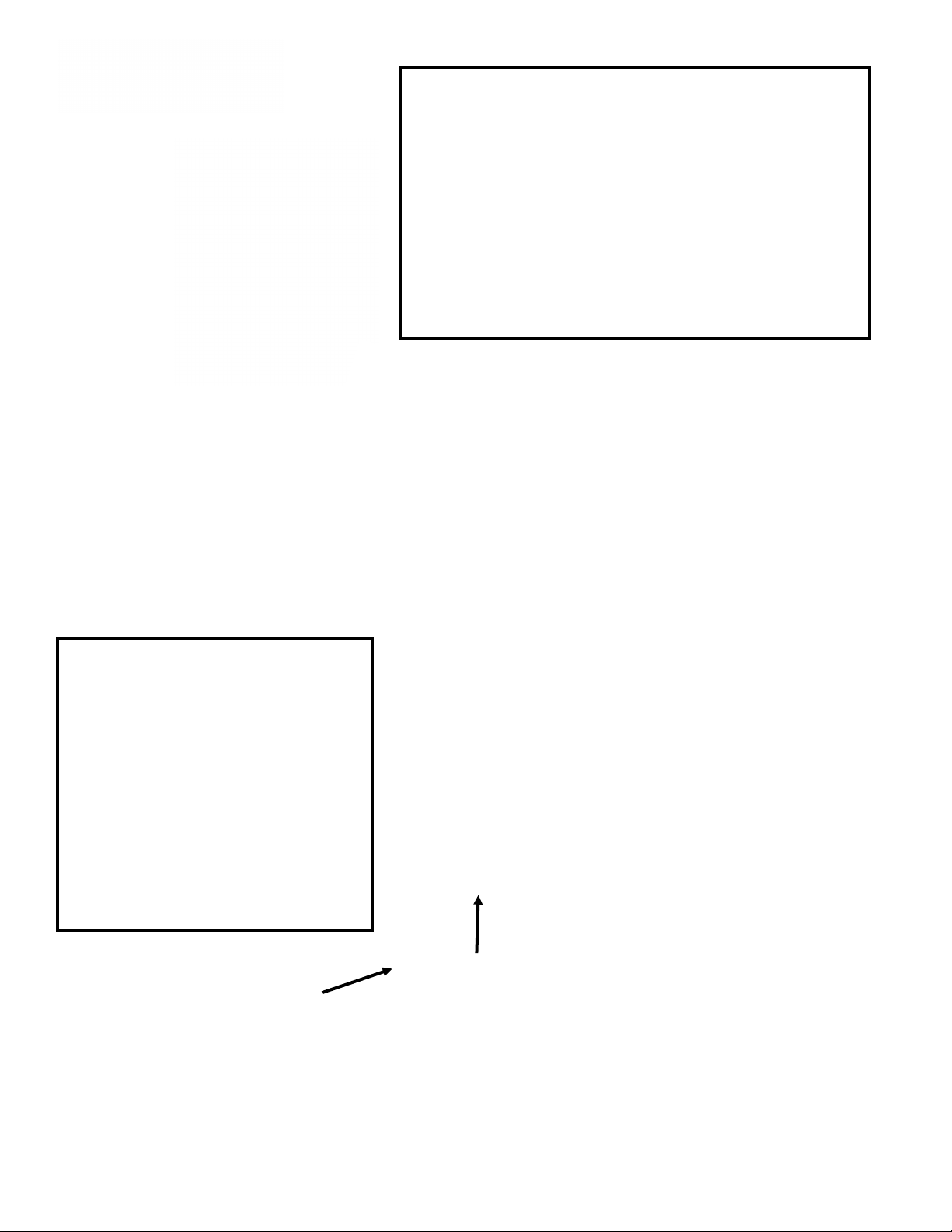
Connect JG Fittings to tower and
“Chilled Water” and “Carb Water”
lines to the bulk head connections
on chiller.
Connect the U bend JG fitting at
the tower end of the trunkline to
loop the red recirc lines. And
connect these lines to ‘Recirc” bulk
head fittings at the chiller.

For CP2000-RUC-BH
CR-KIT-CPUC
Install Kit for CP2000-UC to CBR-V2 Tower 112019
QTY Part # Usage
6 6' Insulated Trunkline 1/4" product CP-4L14 Connects CP2000 Chiller to Draft tower w/re-circ
1 3/8 Tube x 9/26-24 Female Adapter PSEI6012U9 quick connect fitting adaptor to a 3/8" anglestop water valve
2 JG 3/8" mpt to 3/8" Tube PI011223S fittings for CR-14FC Watet Filter head, inlet and outlet.
1 JG reducer, 1/2" stem to 3/8 tube PP062012W Fittings for inlet of CR-14FCP filter system, pre-filter inlet
1 JG reducer 3/4" MPT to 1/2" tube PSEI012026 Fittings for inlet of CR-14FCP filter system, pre-filter inlet
2 JG reducer, 3/8 stem to 1/4 tube PP061208W Reducing union, to connect product hoses to tower fittings
2 JG 90 1/4" smooth to 1/4 PP220808W Optional Product water outlet connections on unit
5
JG 90 3/8" Smooth to 3/8 PP221212W Optional Recirc outlet connections on unit and water filter
1 JG U shape union 3/8" to 3/8" PIUB12S U bend to complete water re-circ circuit from trunkline at tower.
1 JG 3/8 to 3/8 Union PP0412W Water inlet fitting. Union fitting for splicing in 3/8 hose
2 JG 1/2" mpt to 3/8" PI451214FS JG fittings for Shurflo Water Reg inlet and outlet
1 Water Pressure Reducer Valve, 50 psi 183-150-NF Use after the water filter to regulate pressure feeding unit to 50
1 12' section of 3/8 OD Tube PE-12-EI 12' Hose for Water Filter and Inlet connections
15 JG 3/8 Locking Clips PIC1812R Collet locking clip for 3/8" JG fittings
4 JG 1/4 Locking Clips PIC1808R Collet locking clip for 1/4" JG fittings
1 15' Role of Armaflex tape insulation tape to wrap product and re-circ lines and tower
4 15" Zip Ties For securing hose and water reg to wall.
Fitting to hook up a CR-14FC Filter system to a Crysalli Countertop CP2000-UC-BH and Tower or Facuet
Water Pressure Reducer Valve with 1/2" PI451214FS JG fittings screwed on.
CBR-V# Tower comes with super seal fittings for SS Tubes
Insulate Wrap all exposed fittings and lines at the chiller and tower
with the Armaflex insulation tape to prevent sweating of the hoses and temp loss.
Optional Accessory Avaliable:
CR-LBS10-JG, Inline Water Leak Detector and Auto Water Shutoff.
For questions or assistance with install contact Crysalli 510-732-0100 or your local Distributor.
Description
1/4" water inlet
hose with 3/8"
smooth end JG
fitting.
CO2: 1/4"
braded hose
with ss fitting
3/8" Inlet and
Outlet fpt. Use JG
PI011223S on
Connect
here
Always
complete the
recirc loop
and wrap fittings
and hose with
inualted tape
Clear Hose is Overflow
Use
PSEI6012U9 angle
stop adaptor
CR-4L14 Trunkline:
1/4" Product hoses
3/8" Recirc hoses
Water Pressure Reducer
with 3/8 JG fitting 3/8 OD
hose hookup.
6
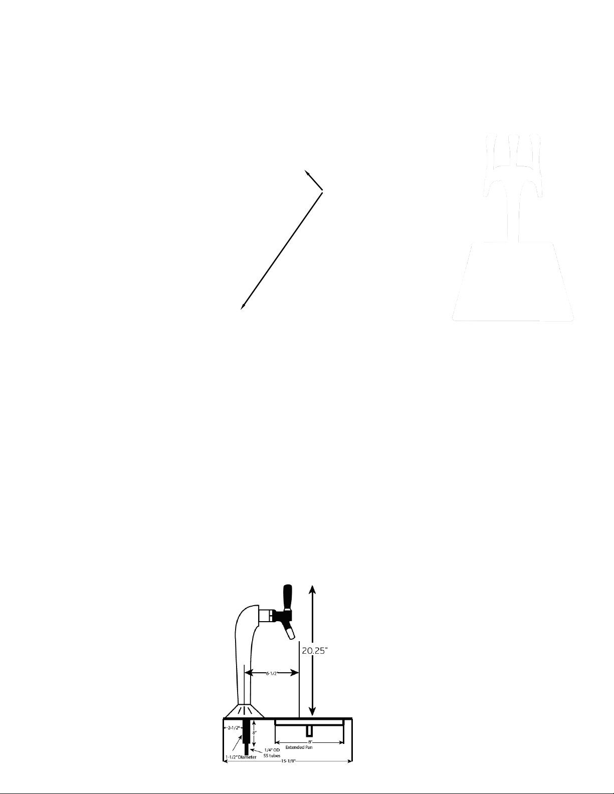
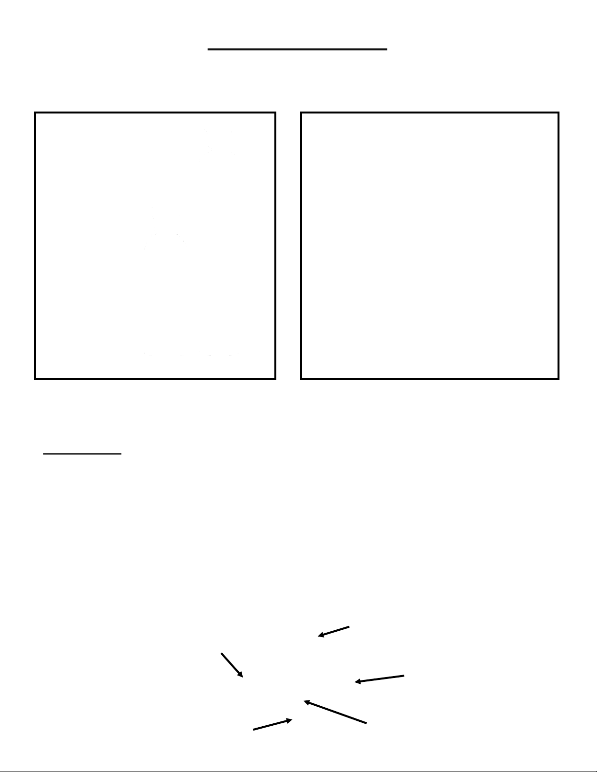
Mounng the RDP-1SSQ or RDP-3SS Recessed Drain Pan
RDP-1SSQ RDP-3SSQ
Counter requires a Square
cut for drain pan secon
and Hole cut for tower:
2” 2”
RDP-1SSQ for use with:
• CBR-V1C/W Tower
• CBR-V2C/W Tower
• LIT-V2C Tower.
• CM-2-PB-SB Push Buon
Specs:
• 12” x 15 1/8” Overall
• 2” Tower Hole on pan
• 10 3/8” x 8 1/2” Drain Pan
• 1/2” Dia Copper Drain Stub
• CBR-V1: 1 3/8” Hole
• CBR-V2: 1 1/2” Hole
• CBR-V3: 1 7/8” Hole
• LIT-V2C: 2” Hole
• LIT-V3C: 2” Hole
RDP-3SSQ for use with:
• CBR-V3C/W Tower
• LIT-V3C Tower.
Specs:
• 15” x 18 1/8” Overall
• 2” Tower Hole on pan
• 13 3/8” x 10 1/2” Drain Pan
• 1/2” Dia Copper Drain Stub
2” Threaded stud for mounng.
10-24 Thread with Locking Nut
and 3”x1” SS Mounng Strip
1/2” Drain Stub, connect hose/
pipe and run to oor sink.

7
Mount and connecng the CBR or LIT towers
Insert tower into the hole in the countertop for it, thread on and ghtened the set nut to secure tower.
Locate grey SI030812S Superseal Union Elbow Fings supplied with the tower (one per tube). Loosen the
Collet Nut on the ng to the last thread then push the ng onto the 1/4” stainless steel tube as shown
on John Guest instrucon page. Tighten the Collet Nut all the way down to lock ng onto SS tube (failure
to ghten the collet nut can result in a leak or the ng slipping o). You will use the White Plug-In Elbow
ngs to connect the Product line from the trunkline to the tower. It is easiest to aach these ngs to the
product tubes of the trunkline rst (using the red locking clips), then connect them to the Superseal ngs
on the tower tubes (see “CR-4L38 Trunkline Tower End Connecons” page).
SI030812S Superseal Elbow,
loosen collet nut, push into SS
tube and ghten collet nut.
Step #2
Step #1
Locate the Box containing the Tower for the system. A Dra tower such as the
CBR-V2C, CBR-V3C or LIT-V2C are packaged with the Faucet bodies and handles
shipped loose, a Faucet wrench, a set of SI030812S Superseal ngs for the 1/4”
Stainless Steel tubes on the tower, PP221212W Plug In Elbow ngs and Instrucons.
Crysalli 1739 Sabre St. Hayward, CA 94545. 510-732-0100. www.crysalli.com

8
Trunkline: 3/4” Foam
insulaon, with a PVC
exterior wrap.
Four plasc barrier tubes,
wrapped together
Two 1/4” Product tubes:
Natural & White Color
Two 3/8” ReCirc tubes:
Red Striped
Find the two White PP221212W Plug In Elbow
Fings that come with the CBR Tower and the two
grey PP061208W reducing ngs from the CPUC
install kit, and connect them to the Product Tubes.
Find the Grey PIUB12S U-Bend ng in the CPUC
install kit and connect it to the two recirc tubes.
Use the Red locking clips.
PP221212
PIUB12S
Once assembled, connected the stem end
of the Plug In Elbow ngs to the Super-
seal ngs on the tower. Connect the Blue
striped tube to le faucet tube for sparkling
water. Natural to Sll Chilled water. If using
a 3 Valve tower, run a separate hose from
the lter to the 3rd tube for ambient water.
Aer tesng the system for leaks wrap all
exposed hoses and ngs with the
Insulated tap found in the UCM install kit.
Step #3
Step #1
Locate the CR-4L14 Trunkline. 6’ will be included with the CPUC install kit. And Prep both ends for
connecon to the Chiller and Dra tower. This trunkline typically doesn't need to be cut shorter, the extra
length can act as a service loop so the chiller can be moved for maintenance and service. If installing 3
Valve tower, the 3rd water line, ambient water, should be tee’d o the water lter outlet and fed over to
the tower.
Step # 2, Tower End
Cut back the insulaon (or tubes) so 3”
of Tubing is exposed.
Cut the two 1/4” Product tubes back 2”,
so the Red Striped tubes extend past
them at least 2”.
Cut the Tubes square and remove burrs
and sharp edges. Make sure the Red
Striped tubes are cut to the same height.
Step #4
CR-4L14 Trunkline Tower End Connecons
x2
x4
PP061208W
x2
9
Once the Faucet Bodies are aached
to the Tower, thread the Handles on
to the them. Thread down ll the
posion the handle with curve is
facing you, if loose, ghten the black
set nut up to the handle base to lock
the handle in posion. Apply the
round Sparkling and Sll Water
image sckers to the appropriate
handles at the top of them.
Angle the faucet body
vercally straight
Push Faucet onto
the Shank
Set the faucet posion,
push back to lock in
Pull shank nut to faucet
and hand ghten
Tighten shank nut
with Faucet Wrench
Locate the Faucet Bodies, Handles and Faucet
Wrench.
The faucet bodies aach to the shanks, that
are pre-aached to the tower and leak tested.
When aaching the faucet body to the shank,
be sure the faucet is properly aligned before
ghtening it down. Adjusng the faucet angle
when aached to the shank can result in
loosening the shank to tower connecon
which can cause a leak.
Using the Faucet Wrench on the Shank Nut:
• Counter-clockwise ghtens the shank nut
to the faucet body.
• Clockwise loosens it for removal.
Mounng Faucets & Handles to Tower

10
These faucets are designed with a ow control adjustment knob (decrease or
increase the ow of the water) on the right side of the faucet body. It will be
desirable to lock in a lower ow of the sparkling water rather than allowing it to be
adjustable. This can prevent splashing in self service applicaons and will maximize
carbonaon prole of the water (the slower the pour the beer the bubble prole).
The faucets can also “wander” or increase to full ow on its own with use. To lock in
a set ow rate, these faucets are supplied with a Stainless Steel lock washer on the
adjustment knob, once ghtened down it will prevent the knob from being turned or
moving on is own.
Sparkling Water Flow Adjustment Lock Out.
Upon start up of the system, the CR-SSQ1231 Faucets used on the CBR-V1, CBR-V2, CBR-V3,
LIT-V2C and LIT-V3C dispensing towers will need the ow rate adjusted and set.
To set the ow rate & lock the ow adjustment knob (make sure system is on and cold, and CO2 open):
• Locate the black plasc three pronged adjustment knob on the right side of the faucet, and check that
you can freely turn it (you may need to loosen the Phillips head set screw a lile so the knob can turn).
• With a cup under the faucet pull open the handle so sparkling water is owing. While water is owing
turn the knob to adjust the ow rate (clockwise or away from you to decrees the ow).
• Once a favorable ow rate is determined, ghten the set screw (while not turning the knob) so teeth of
washer bite in to the plasc, this will lock the knob so it can no longer be turned or move out of
adjustment on its own.
• Check the ow rate again by lling a cup and conrm if the knob is properly ghtened down so it cant be
turned by hand.

11
Installing the Water lter system, Water Regulator and Angle Stop Adaptor.
Locate the water lter head assembly and
lter cartridge. Then locate the 2
PI011223S 3/8” tube to 3/8” NPT ngs in
the Install Kit. These are your inlet and
outlet ngs for the Water lter system.
Wrap some Teon tape around the
threads of the NPT ng, aach them to
the two ends of the lter manifold.
Mount the Filter manifold on
the wall with at least 3” of
clearance at the boom of
the lter so it can easily be
removed and replaced.
To Crysalli
Chiller unit
The Install kit comes with 12’ of the Blue or Black
PE-12-EI Tubing. Cut this to the appropriate length for
inlet and outlet needs. Your install kit may have
some 1/4” braided hose in it. That hose is for the CO2
only. Do Not use the braided hose on JG ngs.
NOTE: Always reference local plumbing
codes for the use requirement of a back
ow preventer, as well as type and
locaon within the system.
Locate the 183-150-NF
50 PSI Water Pressure
Reducing Valve and two
PI451214FS ngs from
the UCM install kit. Aach
the Fings to inlet and
outlet of the WPRV.
Install Reg with Arrows
poinng to the UCM unit
Locate the PSEI6012U9
Angle stop adaptor in
the UCM Install Kit.
Locate the angles stop
water source feeding
the system, remove the
compression nut and
ferule ring from it and
replace with the
PSEI6012U9 ng.
PI451214FS
183-150-NF
PI011223S
12
9’ Black Electrical Cord with NEMA 5-15 Plug
end should be plugged into a dedicated 120V
outlet.
Note: GFI outlets are not recommended since
they can trip when compressor cycles on.
¼” Braided CO2 Hose with
Stainless Steel ¼” Flare nut
end. Connects to CO2 Reg
Hose marked “CO2”
¼” Braided Water Inlet hose with
3/8” push in stem ng end.
Fits into outlet end ng of the
50 PSI water pressure reducer.
Hose Marked “WATER”
If unit is supplied with a Clear Overow vent
hose it should be routed to a oor sink if
accessible and posioned per plumbing
code.
Place the unit in the cabinet space, with at least 4” of
space behind it for clearance for the trunkline bundle,
connecons and chiller vents louvers on the side panels.
Do not block any of the venlated panels on the chiller.
Install CR-TFB1 Fan Box in cabinet at this me if using one.
Locate bundled Electrical cord, Water hose, CO2 hose and
Clear overow hose coming from the boom of the chiller
and unwrap them. (some units do not have clear overow
ow hose, and will drain to the drip pan)
CR-TFB1
Oponal Accessory
Unwrap Water inlet, CO2 inlet,
Overow Drain and Electrical

13
Locate the two 3/8” PP221212W
and two 1/4” PP220808W Elbow
ngs as well as two each of the
red locking clips from the CPUC
install kit. Connect these ngs
to the trunkline hoses end rst,
then to the upper outlets on the
back of the chiller.
Connecng the CR-4L14 Trunkline to the CP2000-R-UC-BH Chiller
If your trunkline will point
downward, cut your white hose
for sparkling water, 1” shorter
than the other three. Then add
ngs
If your trunkline will point
upward, leave the white hose
long and cut the other three
1” shorter than it.
The CP2000-R-UC-BH has four bulk head outlet connecons to
aach the trunkline too. Two horizontal 3/8” connecons for the
red striped re-circ lines and two 1/4” vercal connecons for the
Product water lines. Sll Chilled water is marked “PLAIN WATER”.
Sparkling Water is marked “CARB WATER”. With your trunkline
prepared with the elbow ngs aached as described above you
can now aach it to the chiller by pushing the ngs into the
matching outlets. Aer you leak checked the ngs, wrap these
ngs and hoses in the insulated tape to prevent sweang.
Cung the hose ends for connecon to the Chiller:
Downward poinng
trunkline connecon
Upward poinng
trunkline connecon Wrap all exposed
hoses and ngs in
insulated foam tape.

14
Connecng CO2 and Filling Water Bath
The Hose for the CO2 connecon is 6’ long, 1/4” braided hose with a 1/4”
are nut on the end extending out from the chiller near the water inlet.
Route this hose to the locaon of the CO2 tank. If addional hose is
required, the UCM install kit comes with an addional 8’ of 1/4” braided
hose*, a 1/4” Barb Union and 10.5 Oeker Clamps to extend it.
*WARNING: do not use this extra 1/4” braided hose with John Guest ngs
for the water inlet or water lter connecon, it is not the correct OD or tube
type to work with these ngs and will result in leaks.
If using dedicate CO2 tank, Locate the CR-3741 Primary High Pressure CO2
Regulator. Unbox it and be careful to locate the 1/4” Nylon Washer taped to
the packaging. Insert this washer into the are nut on the end of the hose
and thread it on to the 1/4” mpt are on the CO2 reg. Locate the carboard
washer with the CO2 Tank and thread CO2 Reg to Tank, making sure its ght.
For Bulk CO2 tank use or shared CO2 systems, use the CR-T5251SN
Secondary High Pressure CO2 Regulator to regulate .
Flare Nut with
Nylon Washer in it
CR-3741
Route the Clear Over Flow Water Bath Drain hose from the back of the unit to a oor sink or oor drain.
The Water Bath must be lled with water for the system to work and build an Ice Bank. This water is not used
for consumpon, it is only used to form an Ice Bank around the refrigeraon coils and chill the water owing
through the water cooling coils. Water will drain from the over ow hose upon inial start up as the ice bank
forms. Aer that only periodic condensaon may drip from the over ow hose.
Remove the Lid of the Chiller to expose the Water Bath area. Fill this area with water (preferably non-ltered)
up to the White Stand Pipe, covering the carb tank, water coils and refrigeraon coils.
Fill Bath with 2.5 gallons of
Water or up to the white stand
pipe, before turning on.
Water bath can be drained by
pulling the white standpipe
which will drain to the clear
overow hose or into the drip
pan.
Water bath will freeze a 6 pound ice
bank around refrigeraon coils.
Roughly 1/3 of the bath will be ice
along the side while water around the
chilling coils and carb tank stays liquid
and is agitated
CR-T5261SN
15
CO2 information
CO2 Tanks can be sourced and refilled from local Beverage CO2
Companies (both Bulk and or Tank) and even Welding Supply companies.
On Average 1 Pound of CO2 will be used for every 5 gallons of sparkling
water. Therefore a 20 lb. Tank should carbonate 100 Gallons
(or 12,800 oz’s, or 378 Liters of sparkling water)
WARNING: CO2 Can be Dangerous. CO2 Cylinders contain high pressure
gas which can be hazardous if not handled properly. Follow all CO2
regulator instructions (found with CO2 regulator). And other safe handling
instructions from the CO2 tank supplier.
----------------------------------------------------------------------------------------------------------------------------------------------
CR-3741 High Pressure CO2 Regulator 0-160 PSI:
Attaches to 5-100 lb CO2 tanks. Set to 75 PSI
(Note: Low Pressure Beer Regulators 0-50 psi, will not work properly with Crysalli)
Common CO2 Tank
Cylinder sizes in
Commercial use:
Use with Primary
High Pressure
Reg CR-3741
Common Bulk CO2 Tanks:
Use with Secondary High
Pressure Reg
CR-T5261SN
27.5”
8”
8”
47”
Output Pressure Gauge:
Shows CO2 output pressure
setting. Set to 75 psi.
Fill Level Gauge: Volume of CO2
in Tank. Tank is empty when
needle is in the red zone or zero
Pressure Adjustment screw
and locking nut.
Threaded Connection to
CO2 Tank
1/4” Male Flare connection to
Crysalli Chiller. Use Nylon washer
supplied with regulator in fitting.

16
CP2000-R-UC-BH & CBR Tower Cleaning and Maintenance Recommendaons.
Daily:
Wipe down the unit or dra tower, cleaning and drying all surfaces.
(Use window cleaner on mirrored and chrome nishes).
Clean and dry drain pan and drain grate. Check that water is draining, pour warm water down drain if
necessary.
Check over faucets for acon and hand ghten any loosened handles or nuts on them to prevent
leaks. The set nut holding the handle down will loosen with use. As can the shank nut.
Check ow from faucet, loosen, readjust and ghten ow control knob as needed.
Check that ow, temperature and carbonaon of water poured from the unit are consistent to
average use.
Weekly:
Clean the faucets by wiping them down. If there is any scale or slime submerge them in cleaners/
sanizer and use a brush on them. Check the faucets over for leaks and ghten part to stop the
leak. Reference the SSQ Tech Guide document for more details on maintaining the faucets.
Check CO2 level at CO2 tank.
Monthly:
Check for good water pressure at the water lter system by running water from ush valve on lter.
Visually check pre-lter in clear bowl on water lter system (if applicable) to determine if it
needs replacing. Use only EPC5-10 replacement pre-lter cartridge.
Quarterly:
Check the water bath level, either top o or drain, clean and rell.
Semiannually:
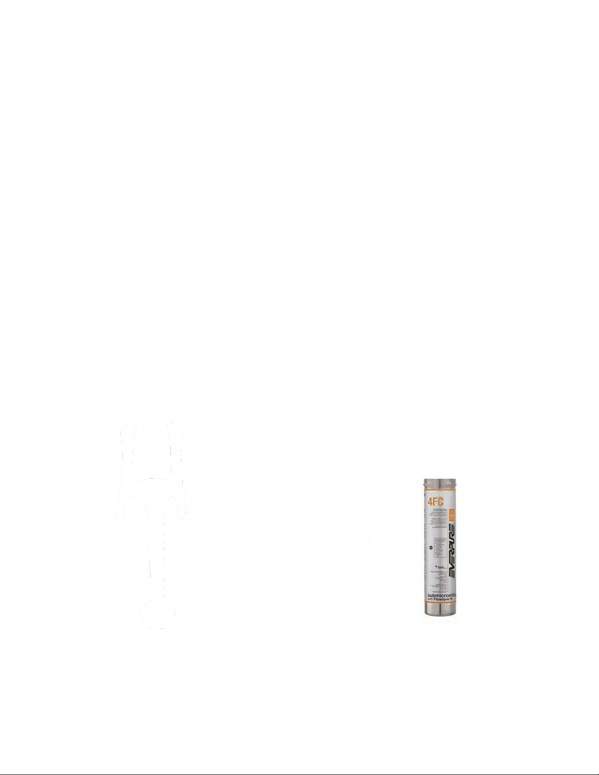
Change the water lters. Use only 4FC replacement lter cartridges.
Drain water bath, clean and rell with new water and add a cap full of sanizer.
Remove and disassemble faucets for cleaning and inspecon.
Annually:
Inspect internal water bath components such as Agitator/re-circ pump and blade, check valves for
CO2 and Water, and all hose connecons.
Flush and rinse system with food safe sanizer (this work should be performed by a cered service
tech).
Model Number:________________ Serial Number: ___________________
Install Date: _____________ Installer/Servicer: ________________________
Crysalli 1739 Sabre St. Hayward, CA 94545. 510-732-0100. www.crysalli.com
Popular Water System manuals by other brands

IXOM
IXOM MEDORA GridBee GS-12 Operation & maintenance manual

AmeriWater
AmeriWater 00HRO64800 Operation & maintenance manual

Kohler
Kohler 10611A-NA installation instructions and home owner's guide

Whirlpool
Whirlpool WHER12 Installation and operation manual

Kärcher
Kärcher WATERCLEAN 600 CD Service handbook

Eco-Smart
Eco-Smart METLUND D’MAND S Series Installation and operating instructions


CIVIQ
CIVIQ Elkay LZS8WSS2K Trouble Shooting Manual & Preventative Maintenance Guide

Franke
Franke Irena Series Installation and user manual

Zip
Zip HydroTap G4 802701 user guide

IXOM
IXOM SolarBee SB2500 owner's manual

Santevia
Santevia Gravity Water System Maintenance manual

Kenmore
Kenmore 625.384700 manual