Page 1 Page 2 Page 3
Be Careful
Do not plug the power cord into an electrical receptacle until system is installed and in place.
Operation of the system without being plumbed into the water lines will burn out the pump prema-
turely and void the warranty.void the warranty.
void the warranty.void the warranty.
void the warranty.
Pre-Installation Checklist
1.1.
1.1.
1. Check the package contentsCheck the package contents
Check the package contentsCheck the package contents
Check the package contents
Your Metlund SystemMetlund System
Metlund SystemMetlund System
Metlund System Includes:
• A pre-assembled Metlund Controller/Circulator Pump/Zone Valve Assembly
• S-46 models will not show zone valve. Zone Valve is inside the pump housing.
• Compression fit copper T’s (S-01PFR). (Homes with galvanized pipes will need
galvanized T’s).
• A plastic bag containing: one (1) push-button
• (If wireless remote option was purchased) one transmitter, one receiver, one 12V
battery, three gray wire nuts & three screws.
Check the components for visible damage and contact your supplier immediately if anyCheck the components for visible damage and contact your supplier immediately if any
Check the components for visible damage and contact your supplier immediately if anyCheck the components for visible damage and contact your supplier immediately if any
Check the components for visible damage and contact your supplier immediately if any
damage is found.damage is found.
damage is found.damage is found.
damage is found.
2.2.
2.2.
2. Make sure you have the tools to do the jobMake sure you have the tools to do the job
Make sure you have the tools to do the jobMake sure you have the tools to do the job
Make sure you have the tools to do the job
No special tools are required to install the Metlund SystemMetlund System
Metlund SystemMetlund System
Metlund System other than those tools usually
needed in any plumbing job. They include:
• Pipe wrench or crescent wrench
• Pliers
• Small Phillips head and medium flat head screwdriver
• Wire strippers
• Drill and 5/8" drill bit
• Soldering equipment (if applicable)
3.3.
3.3.
3. Determine where you will install The SystemDetermine where you will install The System
Determine where you will install The SystemDetermine where you will install The System
Determine where you will install The System
Typically, this should be at the fixture farthest away from the water heater. If your hot water
supplylineruns intwo separatedirections fromthewater heater,you mayneedmore thanone
Metlund SystemMetlund System
Metlund SystemMetlund System
Metlund System to satisfy all of your hot water requirements.
2. After installation adjustments2. After installation adjustments
2. After installation adjustments2. After installation adjustments
2. After installation adjustments
CHECK THE SYSTEM CAREFULLY TO MAKE SURE THE INSTALLATION IS FREE OFCHECK THE SYSTEM CAREFULLY TO MAKE SURE THE INSTALLATION IS FREE OF
CHECK THE SYSTEM CAREFULLY TO MAKE SURE THE INSTALLATION IS FREE OFCHECK THE SYSTEM CAREFULLY TO MAKE SURE THE INSTALLATION IS FREE OF
CHECK THE SYSTEM CAREFULLY TO MAKE SURE THE INSTALLATION IS FREE OF
WATER LEAKS.WATER LEAKS.
WATER LEAKS.WATER LEAKS.
WATER LEAKS.
All Electronic Sensitivity Adjustments are pre-set at the factory. If adjustments areIf adjustments are
If adjustments areIf adjustments are
If adjustments are
necessary please call 1-800-638-5863 for technical help prior to making anynecessary please call 1-800-638-5863 for technical help prior to making any
necessary please call 1-800-638-5863 for technical help prior to making anynecessary please call 1-800-638-5863 for technical help prior to making any
necessary please call 1-800-638-5863 for technical help prior to making any
adjustments.adjustments.
adjustments.adjustments.
adjustments. However, please make sure the off sensor (green tip wire), is firmly attached
and is touching the pipe. The sensor is designed to signal the controller to shut off
automatically when hot waterhot water
hot waterhot water
hot water has reached your fixture, and not to reactivate if hot waterhot water
hot waterhot water
hot water is
at the fixture. Review the troubleshooting page for additional information.
Wireless Remote Option - R0954
Wiring The Receiver
The remote receiver is the white rectangular box with the three protruding wires: black, white & green. ThisThis
ThisThis
This
does not need batteries.does not need batteries.
does not need batteries.does not need batteries.
does not need batteries. Wire the receiver directly to the corresponding wires on the controller by twisting each
same colored wire together with gray wirenuts provided. Receiver should be mounted toward front of cabinet.
(Range of transmitter is about 70’). If transmitter will activate system from short distance, but not from further away,
receiver may need to be relocated for better reception. Strapping receiver to front of drain trap facing outward will
optimize reception.
Installing Batteries to the Transmitter
Open transmitter with a small flat head screwdriver by inserting screwdriver into slot to release catch. Load
battery with negative side of battery toward spring. Carefully replace cover. When button is depressed, red indica-
tor light should turn on. Numbered jumper pins are inside the transmitter and receiver. The signal frequency can be
changed by removing the same numbered pins from both the receiver and transmitter. This should only be neces-This should only be neces-
This should only be neces-This should only be neces-
This should only be neces-
sary when two D’MANDsary when two D’MAND
sary when two D’MANDsary when two D’MAND
sary when two D’MAND
®®
®®
®
Systems are in same home or your neighbor has the system.Systems are in same home or your neighbor has the system.
Systems are in same home or your neighbor has the system.Systems are in same home or your neighbor has the system.
Systems are in same home or your neighbor has the system.
“Installations shall be in accordance with the manufacturer’s instructions“Installations shall be in accordance with the manufacturer’s instructions
“Installations shall be in accordance with the manufacturer’s instructions“Installations shall be in accordance with the manufacturer’s instructions
“Installations shall be in accordance with the manufacturer’s instructions
per the requirements of the Uniform Plumbing Code (UPC)”per the requirements of the Uniform Plumbing Code (UPC)”
per the requirements of the Uniform Plumbing Code (UPC)”per the requirements of the Uniform Plumbing Code (UPC)”
per the requirements of the Uniform Plumbing Code (UPC)”
Installing The Metlund
®
D’MAND
®
System for all S-Series Systems
This is for installation of the PF Accessory T’s only.This is for installation of the PF Accessory T’s only.
This is for installation of the PF Accessory T’s only.This is for installation of the PF Accessory T’s only.
This is for installation of the PF Accessory T’s only.
These do not replace the existing instructions includedThese do not replace the existing instructions included
These do not replace the existing instructions includedThese do not replace the existing instructions included
These do not replace the existing instructions included
with your system. Be sure you have read the instruc-with your system. Be sure you have read the instruc-
with your system. Be sure you have read the instruc-with your system. Be sure you have read the instruc-
with your system. Be sure you have read the instruc-
tions carefully before proceeding with your installation.tions carefully before proceeding with your installation.
tions carefully before proceeding with your installation.tions carefully before proceeding with your installation.
tions carefully before proceeding with your installation.
You have purchased a Metlund Hot Water Demand
System that is equipped with the PF accessory pack-
age.The1/2” male thread adapters have already been
pre-sweat to your Metlund System.
Enclosed with your system, are two T’s designed to sim-
plifyyourinstallationto1/2”copperhotandcoldsupplies.*
To Install Your “T” FittingsTo Install Your “T” Fittings
To Install Your “T” FittingsTo Install Your “T” Fittings
To Install Your “T” Fittings
1. Turn off the house water supply.
2. Open the hot and cold faucets at the fixture chosen for installation.This will relieve the water
pressure from the hot and cold water pipes.
3. Remove the shut-off valves that supply hot and cold water to the sink from the 1/2” copper
pipe. For ease of installation, leave the compression ring and nut from the angle stop on the
hot and cold water supplies.
4. Remove the compression ring and nut from the enclosed compression fitting on the PF-T’s,
and slide onto the other end. Attach the existing nut and ring to the end of the threaded T
and firmly tighten.
5. Install the remaining compression ring and nut to the shut-off valve,slide onto the 1/2” side of
the PF-T and firmly tighten.
6. Now you are ready to attach flex lines from the 1/2” male thread of the PF-T’s to your MetlundMetlund
MetlundMetlund
Metlund
D’MANDD’MAND
D’MANDD’MAND
D’MAND SystemSystem
SystemSystem
System. (Teflon tape is recommended for the 1/2” threaded fittings.)
7. Refer to Page 3 - “Installing the Demand Button(s)” and “Wireless Remote Option”.
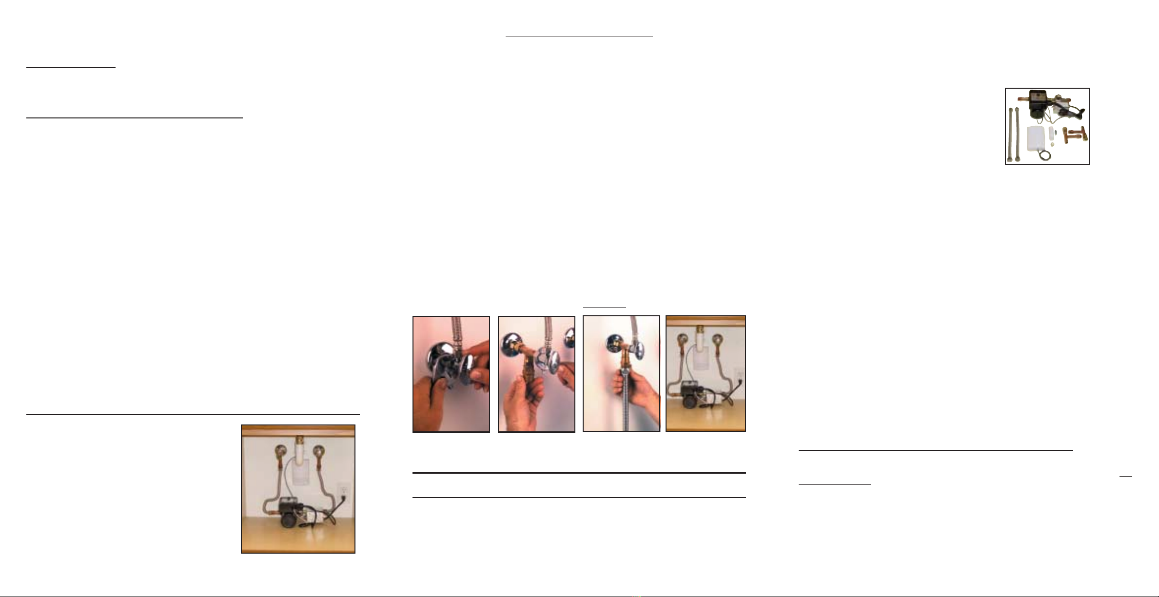
1. Turn off water1. Turn off water
1. Turn off water1. Turn off water
1. Turn off water
supply andsupply and
supply andsupply and
supply and
remove angle stops.remove angle stops.
remove angle stops.remove angle stops.
remove angle stops.
2. Install & tighten2. Install & tighten
2. Install & tighten2. Install & tighten
2. Install & tighten
T’s (included),T’s (included),
T’s (included),T’s (included),
T’s (included),
attach angle stops.attach angle stops.
attach angle stops.attach angle stops.
attach angle stops.
3. Install copper flex lines3. Install copper flex lines
3. Install copper flex lines3. Install copper flex lines
3. Install copper flex lines
or any line withor any line with
or any line withor any line with
or any line with
1/2” inside diameter.1/2” inside diameter.
1/2” inside diameter.1/2” inside diameter.
1/2” inside diameter.
4. Connect Metlund4. Connect Metlund
4. Connect Metlund4. Connect Metlund
4. Connect Metlund
System, install pushSystem, install push
System, install pushSystem, install push
System, install push
button and plug in.button and plug in.
button and plug in.button and plug in.
button and plug in.
SYSTEM ADAPTS TO YOUR EXISTING PLUMBING!SYSTEM ADAPTS TO YOUR EXISTING PLUMBING!
SYSTEM ADAPTS TO YOUR EXISTING PLUMBING!SYSTEM ADAPTS TO YOUR EXISTING PLUMBING!
SYSTEM ADAPTS TO YOUR EXISTING PLUMBING!
FOLLOW THESEFOLLOW THESE
FOLLOW THESEFOLLOW THESE
FOLLOW THESE SIMPLESIMPLE
SIMPLESIMPLE
SIMPLE STEPS:STEPS:
STEPS:STEPS:
STEPS:
METLUND “NO SWEAT”
* Additional fittings may be required if your supply lines are galvanized or plastic pipe.* Additional fittings may be required if your supply lines are galvanized or plastic pipe.
* Additional fittings may be required if your supply lines are galvanized or plastic pipe.* Additional fittings may be required if your supply lines are galvanized or plastic pipe.
* Additional fittings may be required if your supply lines are galvanized or plastic pipe.
Installation must be as shown aboveInstallation must be as shown above
Installation must be as shown aboveInstallation must be as shown above
Installation must be as shown above
Installing The Metlund
®
D’MAND
®
System for all S-Series Systems
1.1.
1.1.
1. Installation ProceduresInstallation Procedures
Installation ProceduresInstallation Procedures
Installation Procedures
A. Turn off the house water supply.
B. Open the hot and cold faucets at the fixture chosen for installation. This will relieve the
water pressure from the hot and cold water pipes.
C. Remove the shut-off valves that supply the hot and cold water to the sink.
D. Install T-fittings to the pipe stubs from the hot and cold water supply.
This is the recommended position for installing the
Metlund SystemMetlund System
Metlund SystemMetlund System
Metlund System with the flow of the hot water into the
pump side of the system and the valve side into the cold
water line. The pump should lay on its side with the con-
troller on top. (Figure 1)
4.4.
4.4.
4. Installing the Demand Button(s)Installing the Demand Button(s)
Installing the Demand Button(s)Installing the Demand Button(s)
Installing the Demand Button(s)
To install the Demand Button, follow these steps:
A. Drill a 5/8" hole into the desired location.
B. Insert the 5 foot gray wire from the controller through the back side of the hole and
connect it to the push button switch. Then, firmly insert the push button back into the
hole. Additional push button switches can be spliced into the same wires. It is
important to use a button comparable in quality to the button provided.
3.3.
3.3.
3. Try the MetlundTry the Metlund
Try the MetlundTry the Metlund
Try the Metlund®®
®®
®System and check water temperatureSystem and check water temperature
System and check water temperatureSystem and check water temperature
System and check water temperature
Once installed, turn water supply on and plug in the system. (Pump will automatically turn
itself on when it is initially plugged in without pushing the demand button). The Metlund
System will continue to operate until the sensor signals that hot water has arrived, then it will
automatically shut off. To test the system again, wait until pipes cool down. You may then test
the system by pushing the demand button, or to pre-test your system after plugging the unit
into 110v outlet, place a hot rag over thermosensor located to the right of the ump housing.
The unit will shut off immediately. Remove rag from sensor and test remote switches.
To operate the Metlund System from another location in the home, place remote button in
desired location. Push remote button (red activation light will light up when pushed), wait a
few seconds for system to cycle. You may now turn on hot water. NOTE: The MetlundNOTE: The Metlund
NOTE: The MetlundNOTE: The Metlund
NOTE: The Metlund
Controller is designed with an automatic safety feature that will shut off the pump inController is designed with an automatic safety feature that will shut off the pump in
Controller is designed with an automatic safety feature that will shut off the pump inController is designed with an automatic safety feature that will shut off the pump in
Controller is designed with an automatic safety feature that will shut off the pump in
approximately three minutes.approximately three minutes.
approximately three minutes.approximately three minutes.
approximately three minutes.
1.1.
1.1.
1. Installation Procedures (continued)Installation Procedures (continued)
Installation Procedures (continued)Installation Procedures (continued)
Installation Procedures (continued)
NOTE: Using piping with less than 1/2" inside diameter will restrict the flow of theNOTE: Using piping with less than 1/2" inside diameter will restrict the flow of the
NOTE: Using piping with less than 1/2" inside diameter will restrict the flow of theNOTE: Using piping with less than 1/2" inside diameter will restrict the flow of the
NOTE: Using piping with less than 1/2" inside diameter will restrict the flow of the
water, causing it to take longer for hot water to arrive. Before sweating 1/2” pipewater, causing it to take longer for hot water to arrive. Before sweating 1/2” pipe
water, causing it to take longer for hot water to arrive. Before sweating 1/2” pipewater, causing it to take longer for hot water to arrive. Before sweating 1/2” pipe
water, causing it to take longer for hot water to arrive. Before sweating 1/2” pipe
to zone valve, be sure zone valve is in manual position.to zone valve, be sure zone valve is in manual position.
to zone valve, be sure zone valve is in manual position.to zone valve, be sure zone valve is in manual position.
to zone valve, be sure zone valve is in manual position.
E. Install the Metlund SystemMetlund System
Metlund SystemMetlund System
Metlund System between the hot and cold lines, but be sure that the arrows on
the pump and the valve point from the hot side to cold as shown in Figure 1.Figure 1.
Figure 1.Figure 1.
Figure 1.
F. Re-install the shut-off valves to the water
supply and sink.
Figure 1Figure 1
Figure 1Figure 1
Figure 1


