Crystal Clean 2734 User manual
USER GUIDE
MODEL
2734
Ultrasonic Cleaning System
www.crystal-clean.com
Heritage-Crystal Clean LLC · 2000 Center Drive Suite East C300 Hoffman Estates, IL · 60192
877-938-7948 · contact@crystal-clean.com

2
ULTRASONIC CLEANING SYSTEMS ULTRASONIC CLEANING SYSTEMS
INDEX
GENERAL VIEW..............................................................................................................................................................................3
SAFETY WARNINGS.......................................................................................................................................................................3
SET UP.............................................................................................................................................................................................4
BEFORE START UP........................................................................................................................................................................4
CONTROL PANEL AND FUNCTIONS ............................................................................................................................................5
START UP AND CLEANING PROCEDURES .................................................................................................................................6
WATERFLOW SYSTEM ......................................................................................................................................................9
AIR PRESSURE REGULATOR ............................................................................................................................................9
ADJUSTING THE SPEED OF THE PNEUMATIC CYLINDER .............................................................................................9
BAG FILTER TTF1 AND TTF2 .............................................................................................................................................9
MAINTENANCE.............................................................................................................................................................................10
POSSIBLE DISFUNCTIONS .........................................................................................................................................................11
TECHNICAL SPECIFICATIONS....................................................................................................................................................12
ELECTRICAL AND PNEUMATICS SCHEMES.............................................................................................................................13
RISK ASSESMENT........................................................................................................................................................................18

3
ULTRASONIC CLEANING SYSTEMS ULTRASONIC CLEANING SYSTEMS
GENERAL VIEW
You have just purchased a CRYSTAL CLEAN ultrasonic
cleaning system. We appreciate the confidence shown by
purchasing a CRYSTAL CLEAN equipment.
Each CRYSTAL CLEAN machine has been carefully tested
and has passed our quality controls. However, the lifetime of
the machine depends largely on you, so we recommend you
to consider the information contained in this manual at the
start up and use of your ultrasound equipment. Give special
attention to the instructions that we detail below.
FORESEEN USE
Motor clean range equipment is specially designed for
cleaning engines, engine parts and accessories.
This equipment is designed to cover the needs not only
of car repair shops but also for marine and cogeneration
engines, aeronautic industry and grinding and
remanufacturing engine workshops.
Crystal Clean products achieve a high cleaning quality,
effectively removing any kind of dust: greases, oil or
carbon deposits. Since cleaning is carried out by
immersion, the ultrasonic cleaning achieves a high quality
result in every hard-to-reach areas.
SAFETY WARNINGS
1. Use protective equipment against thermal, chemical
and splashes risk (gloves, goggles, protective clothing,
mask) according safety data sheet of the chemical
product. Gloves and clothes must be thermal
and chemical protective and glasses completely cover
both eyes and the mask should cover both the mouth
and the nostrils.
2. Use safety boots to prevent injury from possible falls of
parts to be cleaned.
3. Perform cleaning and maintenance while the machine
is off.
4. Do not transport the machine with water in the tank.
5. Do not work with the machine if damages are detected.
6. Do not introduce in the machine parts larger than
those indicated as useful measures in the technical
specications.
7. When draining the tank for cleaning, wait until the
temperature lowers befor pouring cold water for
cleaning.
8. Keep the lid open while tank is being drained.
9. Use the machine only for ultrasonic cleaning of parts. It
is not designed for any other applications.
10. Introduce softly the load and center on platform against
rear side (if equipment has platform).
11. Do not place the machine against direct sunlight,
nor next to a heat source. In such cases the internal
temperature of the machine increases and may result
in a malfunction.
12. This machine is designed for indoor use only. In case
of outdoor use, the equipment can be damaged or an
electrical failure may occur.
13. Do not use power wires or plugs in bad condition.
14. Make sure you have a good grounding and appropriate
supply voltage according to the specications of
the ultrasound machine. The electrical installation
where the machine is connected must comply with
current regulations and must be installed by qualied
technicians.
15. Do not touch or unplug the power wire with wet hands.
16. Do not access to the control registers. These areas are
indicated on the machine with this symbol.
In case of disassemble any guard ensure to cut the
electrical and pneumatic supplies before. All the guards
must be assembled again before start the machine
again. Do not work with the guards removed.
17. Disconnect the equipment from the electric network or
in case of a long inactivity
18. During the test and maintenance of transducers,
generator y or any other electric element, it is required
to check that the main switch (which is blocked with a
lock) is on the OFF position or “switched off”, and also
it’s advisable to unplug the machine. This way, we
make sure that the main energy source is switched off.
Otherwise, there is a risk of electric shock.
19. When handling the machine without taking the measures
mentioned in the previous point, the corresponding
personal protective equipment against electrical
hazards must be used.
20. Do not drop any heavy bodies in the tank or press
buttons with sharp objects. It can cause serious damage
to the equipment or electric shock.
21. The transducers are located at the bottom of the tank.
It is very important to avoid hitting the transducers box
and avoid placing parts directly on it.
22. ALWAYS OPEN THE LID before activating the rise of
the platform.
23. Do not spill liquids such as water, acid or alkaline liquids
near the control panel.
24. If a acid cleaning liquid is used the machine may be
damaged, depending of how corrosive the used product
is. Therefore consult us about the product you will
use if it does not belong to those recommended by
CRYSTAL CLEAN®. In any case, it is always necessary
to consider the measures of use and safety of the
product itself, especially those relating to the volatility
and the volume of product to use.
25. The equipment is designed to work with neutral and
basic products (pH above 6,5).
26. Do not use products with a pH lower tan 6,5. In case
of doing so, the machine could be seriously damaged.
27. Do not use ammable products.
28. The working area must be properly ventilated and
workers must be aware of the posible hazards of the
cleaning products that are used. It’s necessary to read

4
ULTRASONIC CLEANING SYSTEMS ULTRASONIC CLEANING SYSTEMS
the safety data sheets before using the product.
Trapping hazard with the machines:
1. Work clothes should t the body and the operator must
not wear any clothing or hanging rings, bracelets,
chains... which may be caught with the moving parts of
the machine causing an injury to the operator.
2. Do not modify nor remove the coverings and protections
of the machine.
3. Do not activate the plataform while there is any body part
inside the tank.
Risk of electrical accidents:
1. Check that the machine, equipments and instalations
are in good condition
2. Stick to the guidelines given in the manuals regarding
disconnection and maintenance of electrical appliances.
3. Do not use equipment when wet, when the operator
is wet or in the presence of water or moisture. The
electrical equipment will be deposited in dry places and
should never get wet.
4. If a fault or malfunction is detected, the operator must call
the Maintenance Service (phone number is indicated in
last page) and he should never try to repair it by himself.
5. In case of malfunction, the operator must inform the rest
of his coworkers, stop using the equipments and prevent
the rest of the workers from using them.
6. Equipment and individual protections used must be
certied.
If you have to work in electrical installations, please remember:
1. Cut off all voltage sources.
2. Block breaking devices (switches, circuit breakers, etc.).
3. Verify the voltage absence.
4. Ground and short-circuit all possible voltage sources.
5. Demarcate and mark out the working area.
This list of safety warnings do not include all possible
misuse of the machine, but it describes the most
predictable. The person responsible for the safety at
the machine owner company must be commissioned to
assess, monitor and control the use of this machine.
SET UP
1. The machine is supplied packed. Check that the
packaging is in good condition before removing it. When
removing the packaging, do not use sharp elements such
as scissors or cutters to avoid marking the machine.
2. Use a forklift to move the machine and make sure that
you use the red points of support when using a pallet and
the blue ones when lifting the machine directly.
3. Distance the unit 300mm / 11.81”. or more from the
walls or from other machines, since the semiconductors
integrated into the generator make it temperature
sensitive. The high temperature may cause malfunction.
4. Connect to a power source of appropriate voltage as
indicated on the equipment. Always ensure the machine
is properly grounded. See equipment specifications.
5. The cleaning tank must be placed horizontally on a firm
surface and leveled.
6. The equipment must be placed in a dry place.
7. The air connection must maintain a constant pressure of
6 bars. (Recommended operating pressure).
8. The size of the water connection for filling and emptying
the tank will depend on the model (See technical
specifications). If there are security overflows, they
must remain open.
BEFORE START UP
Personnel in charge of handling and operating the machine
must have training in handling it and its inherent risks. This
machine carries risks due to chemical substances, electrical
elements and tires.
IMPORTANT: READ THE MANUAL
BEFORE DOING ANY TASK WITH THE
MACHINE.
1. Connect to a suitable electrical outlet (IMPORTANT:
See equipment specifications and check the type
label on the machine).
2. Ensure that the drain valve is closed.
3. Do not operate the ultrasonic equipment without
water. When the machine is started without fluid the
transducers, the heating element and other components
get damaged immediately.
Ensure the tank is full before operating the
equipment.
4. Fill the main tank to its maximum water level. In model
with WFS up to the top of the separator connecting the
main tank with the auxillary tank (see image). Fill the
auxiliar tank by overflowing over the separator.

5
ULTRASONIC CLEANING SYSTEMS ULTRASONIC CLEANING SYSTEMS
Setting up and initial operations must only be carried
out by CRYSTAL CLEAN personnel. At the time of
installation, a representative of CRYSTAL CLEAN will
conduct a demonstration and give all the explanations
deemed appropriate.
Installation and commissioning carried out by
unauthorized personnel can cause damage to both
operators and the machine.
THE USE AND MISMANAGEMENT
The machine is designed for the operator to work at the front,
except for maintenance works where you can access the
machine where necessary.
When the cleaning is done,the pieces will be at an elevated
temperature, it is necessary to use thermal protection gloves
for handling.
Do not put into the machine parts with a higher volume than
30% of the total tank volume.
Do not insert parts whose measures and/or weight are greater
than described in the specications.
You should not work without adequate water level.
To drain the machine it is necessary to wait until the cleaning
liquid has decreased in temperature in order to avoid thermal
contact damage.
Insert the parts to be cleaned in the tank free of ammable
liquids.
IMPORTANT: Always exceed the minimum level
marked. If not so, transducers and heating elements
may get damaged.
5. WFS fill the auxiliary tank through the main tank
(overflowing over the separator).
6. Turn on ultrasounds.
7. Turn on heating element (recommended temperature:
68ºC / 155ºF to 74ºC / 165ºF). Be careful with the hot
parts of the machine, specifically the valves located on
the left side, the cleaning liquid and the parts cleaned
when removed from the liquid.
8. Before cleaning any part, and every time you change the
water of the tank, it is necessary to DEGAS the water.
For this we must let ultrasounds work for 2 to 3 hours,
depending on water hardness. We will know when
the water is degassed when it stops leaving out small
bubbles (oxygen molecules).
When the diluted product is added to the tank, an abrupt
change in water cavitation can be appreciated for about
two minutes. Then the bath is ready to work. Whenever
we add water by accumulated losses when parts are
taken out or by evaporation, it is important to add the
product in the same proportion.
The percentage of the product to be mixed with
the water will depend on the type of product (see
technical data sheet of the product purchased).
9. The ultrasonic unit comes with built-in programming.
However, it can be changed.
10. Do not place parts, cleaning baskets, or cups directly on
the bottom of the tank (on top of transducer box). This
is a common cause of defects in vibration, and also
shortens the life of the transducer.
11. Immerse the parts to be cleaned in the cleaning tank
gently, taking special care not to hit the base or other
components. These incidents can damage the parts or
shorten the life of the transducer.
12. The bath will be effective for longer if we carry out oil
extractions and water filterings. There is no provisions
for water and product exchange as it depends on the
quantity of cleaning performed and the degree of
contamination of parts washing time.
13. Performing extractions of oil and filter the water bath
will last longer. As with changing the bath, there is not a
stipulated periodicity of the filterings and oil extractions
because it depends on the parts to be washed and dirt.
This frequency should be assessed by the staff in
charge of the equipment.
14. When the platform is down, the cover must be closed
before proceeding to the cleaning process.
15. When the cleaning is finished, let the piece drain to
avoid risks of dripping. Make sure it does not drip before
removing from the platform.
6
ULTRASONIC CLEANING SYSTEMS ULTRASONIC CLEANING SYSTEMS
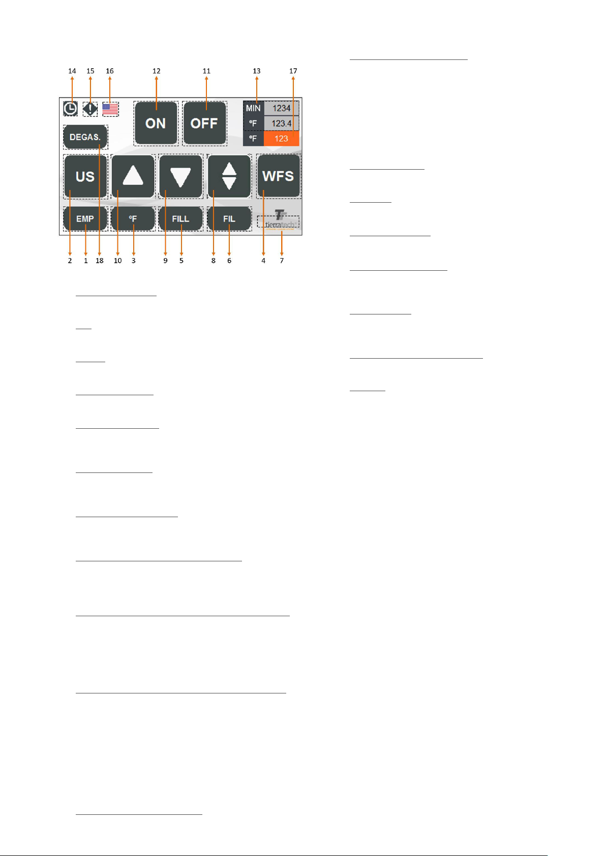
CONTROL PANEL AND FUNCTIONS
1. EMP (if installed): On/Off drain tank function. If this
function is On, the button is highlighted in white.
2. US: On/Off ultrasound function.
If this function is On, the button is highlighted in white.
3. ºC / ºF: On/Off heating function. If this function is On, the
button is highlighted in white.
4. WFS (if installed): On/Off WFS function. If this function
is On, the button is highlighted in white.
5. FILL (if installed): Enables or disables lling tank
function.If this function is On, the button is highlighted
in white.
6. FIL (if installed): Enables or disables tank ltering
function.If this function is On, the button is highlighted
in white.
7. SETTING UP SCREEN:Private access to set up the
machine programming . This option is only available for
the manufacturer.
8. MOVEMENT FUNCTION (if installed): Activates or
deactivates an oscillating movement of the platform
during the cleaning process. If this function is On, the
button is highlighted in white.
9. PNEUMATIC LOWERING PLATFORM FUNCTION (if
installed): Lowers platform for pieces immersion. If this
function is On, the button is highlighted in white.
Movement is activated pressing simultaneously both
buttons “dead man”. If there is only one button you
should press simultaneously the one on the screen.
10. PNEUMATIC LIFTING PLATFORM FUNCTION (if
installed): Raises the platform for loading and unloading
of parts. If this function is On, the button is highlighted
in white.
The movement is accomplished exactly the same way
than the lowering platform.
Any movement (8,9 and 10) that we select it will disable
any other which is ON. Also, if we press an activated
button, we will disable it immediately.
11. AUTOMATIC CYCLE “OFF”: When automatic cycle
is ON this button turns in red. Allows to disable the
12. AUTOMATIC CYCLE “ON”: Automatic cycle activated
(this button turns in green). Once the automatic cycle is
ON all the manual functions will be off. Automatic cycle
connects and disconnects all the consecutive functions.
The timer and the working temperature for each function
will set up in each recipe.
If the platform is installed , it will make a first down
movement automatically, afterwards it will start to make
a continuous movement automatically.
13. MIN FUNCTION: Time left for automatic cycle
(
countdown).
ºC / ºF : Current tank temperature. Pressing on this
button we enter in the recipe screen for automatic cycle.
14. PROGRAMMING: This function allows you to set up a
weekly program.
15. HISTORICAL ALERTS: This button allows you to check
the alarms or warnings . The button will blink and turns in
blue, if there are alarms.
16. LANGUAGES: It allows to change the language on the
screen (If you change to USA it will change to degrees
Fahrenheit).
17. TEMPERATURE SET VALUED: It shows you the target
temperature and pressing on it you can modify.
18. DEGAS: Activates or deactivates ultrasound operating
mode for degassing water (additionally it is required to
activate the US function, button 2). If this option is
active, the border is highlighted in white.

7
ULTRASONIC CLEANING SYSTEMS ULTRASONIC CLEANING SYSTEMS
•RECIPE NUMBER: Set up the recipe number which
you would like to modify. It can be realize until ve
recipe.
•AUT. MIN: Time (minutes) for automatic cycle.
•ºC / ºF : Working temperature.
•WFS SEG: Time (seconds) during the WFS pump is
working.
•FILT MIN:Time (seconds) during the FILTER pump
is working.
•MOVEMENT: Selecting “1”, you will activate the
movement (in platform) on automatic cycle. If “0” is
selected the movement will be disable.
Once a recipe is modied the changes will be released
below. To upload a recipe to the machine you should
select a recipe and press the button HMI>PLC.
To return to main screen press on right below arrow
button.
3. If it´s required, you are allowed to set up a weekly
programming. You must be press the function (14) on
the main screen.
On this screen, it shows a temperature program on a
weekly schedule. To start up this function you should
introduce a “START TIME” ( press ENTER to conrm)
and minutes ( press ENTER to conrm) and active the
weekday button. After, you have to introduce the hours
and minutes in “FINAL TIME” to stop the program.
Once the programming days are selected the buttons
turns in green and you should press the PROGRAM
ON function to release. This function will be disabled if
we selected PROGRAM OFF.
This function will always work with the previous xed
temperature. To set up our cleaning program we press
on the number which is showed the temperature. On
this screen appears a numeric board and you should
press the desired temperature for working. Conrm with
ENTER ( It is not allowed to fix the temperature higher
than 90ºC / 194ºF).
4. The rst program must be to DEGAS the water, applying
ultrasound long enough to stop small bubbles emerge.
The process will last at least 3 hours (it depends on water
hardness). The water must be degassed whenever the
whole bath is changed.
WHEN RUNNING ULTRASOUND, KEEP
TRANSDUCER BOXES UNDER REQUIRED
LIQUID LEVELS. IMPORTANT FAILURE
MAY RESULT IN THE EQUIPMENT IF YOU
DO NOT FOLLOW THESE INSTRUCTIONS.
IMPORTANT:
If, for any reason, the date and time are reseted (because
the touch screen battery is damaged, because the
machine takes a long time off, etc.) you need to follow
the protocol below:
1. Click on the main screen ,option (14) and press on the
following area to set up the date and time:
2. Click on arrows to move along the date and time. Press
on + (to increase number) or press on - ( to decrease
number). Click on SAVE to release the changes. If you
wish to cancel the changes or to exit of the screen, click
on QUIT.
START UP AND CLEANING PROCEDURES
Setting up and initial operations must only be carried
out by CRYSTAL CLEAN personnel. At the time of
installation, a representative of CRYSTAL CLEAN will
conduct a demonstration and give all the explanations
deemed appropriate.
Installation and commissioning carried out by
unauthorized personnel can cause damage to both
operators and the machine.
1. Turn on the switch located on the rear / on the right side
of the equipment (it depends on the model).
2. Select the function (13) to set up the information for the
recipe.
Press on white gaps to set the numeric data for the
following options
8
ULTRASONIC CLEANING SYSTEMS ULTRASONIC CLEANING SYSTEMS
5. Add the recommended amount of cleaning product. The
dosage of the product generally varies between 3% and
5% of the equipment capacity (consult CRYSTAL CLEAN
before adding cleaning product, as it depends on the soil
to be removed and material of parts to be cleaned).
6. Once the liquid has reached the right temperature and
the product is mixed properly, proceed to immerse the
parts.
Press the function (12) and it will activate the automatic
cycle with the recipe which has been uploaded before
in PLC. However, if it requires a manual mode it will able
and disable the different manual functions.
7. During the cleaning process we can activate the
movement function (if installed)(8). This function will
start immediately during all automatic cycle.
8. WFS and FILTER (If included):
• WFS
The WFS system cannot be used when the auxiliary tank
is empty.
The pump has 3 speeds. The fastest one is selected
by default. After a cycle of cleaning, the pump will run
automatically during one minute and it is important to
maintain the security level of the uid for the pump not
to break. In case of manual activation start the cleaning
cycle immediately and before of taking out the pieces
from the tank.
• FILTER
In this function, it activates the lter pump following
the WFS pump. In the manual option it should start
immediately after de WFS function
9. Automatic filling system (5) (if included).
This system allows the machine to maintain a constant
water level in the tank.
Connect a water supply hose to the fill-in solenoid valve.
Once connected, open the fluid flow. A level sensor will
automatically maintain a constant fluid level in the tank.
10. Drained system (if included): The draining will be
always manually when it requires empty the tank for
maintenance task or replacing the bath. Once this
function is ON it will drain the tank until the
minimum security level. To drain the left liquid you must
be press the button in 10 seconds pulses.
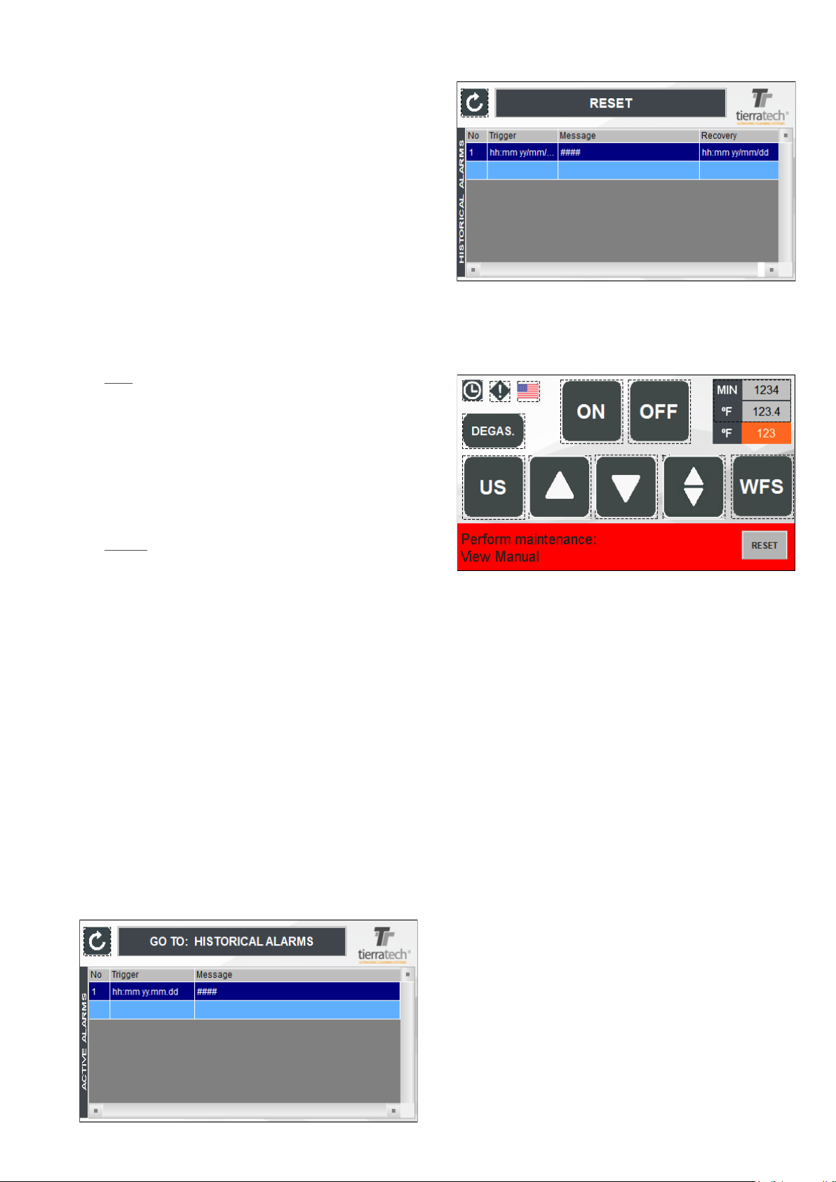
11. Alarms Screen (15): When the icon is blinking it means
there are warnings. If we pressed on , it will show
historical alarms of the machine.
If you press on “HISTORICAL ALARMS” will show a
RESET button which remove all the showed alarms.
ATTENTION: WHEN THE WORKING HOURS ESTIMATED
HAVE BEEN ACCOMPLISHED , IT WILL APPEAR A MES-
SAGE ON THE MAIN SCREEN WARNING ABOUT THE
MAINTENANCE TASK TO FOLLOW. SEE MAINTENANCE
SECTION.

9
ULTRASONIC CLEANING SYSTEMS ULTRASONIC CLEANING SYSTEMS
By adjusting the regulators it is possible to change the
movement speed of the plataform.
This zone indicates the maximum weight that can be raised
with this machine.
BAG FILTER TTF1 AND TTF2
(IF INCLUDED)
Filtering process of the cleaning liquid to reduce contamination.
Regular checking and emptying of the lter bag and its
cleaning are recommended. When the lter gauge exceeds
1 bar, empty the reusable bag.
Every time the lter is opened, to return to operation it must
be purged through the valve located next to the manometer.
Orient the valve hose to the main tank or a can.
To change the lter bag, you must open the lter cover, close
the outlet (to the tank) and inlet (to the lter) valves and
drain it through the drain valve. Replace the bag and leave
everything as at the beginning and purge.
Do not drop small objects into the tank, they may reach
the pump and damage it.
Attention: do not open the lter when hot to avoid injuries.
WATERFLOW SYSTEM
(IF INCLUDED)
With this system, through the pump (described in section 8 of
the previous section), a circulation is created in the uid that
entrains all the oil and other residues that are on the surface
to an auxiliary tank.
With the valves in the open position the pump works to remo-
ve the oil from the main tank to the auxiliary tank. This is the
normal position that the machine should always have.
To extract the oil from the auxiliary tank, proceed as follows:
- Open the drain valve and install a bucket for the drainage of
the oil. This operation is most effective by applying it with low
ow rate in the injection. (This valve must always be closed
in case it is not performing this operation)
- Inject water (very slowly) through the valve located in the
lower part of the equipment (The amount of oil that comes out
will be smaller the less the injection of water into the tank).
AIR PRESSURE REGULATOR
(IF INCLUDED)
In the equipment there is the possibility of regulating the
pressure of the compressed air (see the manometer) of the
pneumatic system of the platform or any other system that
requires air.
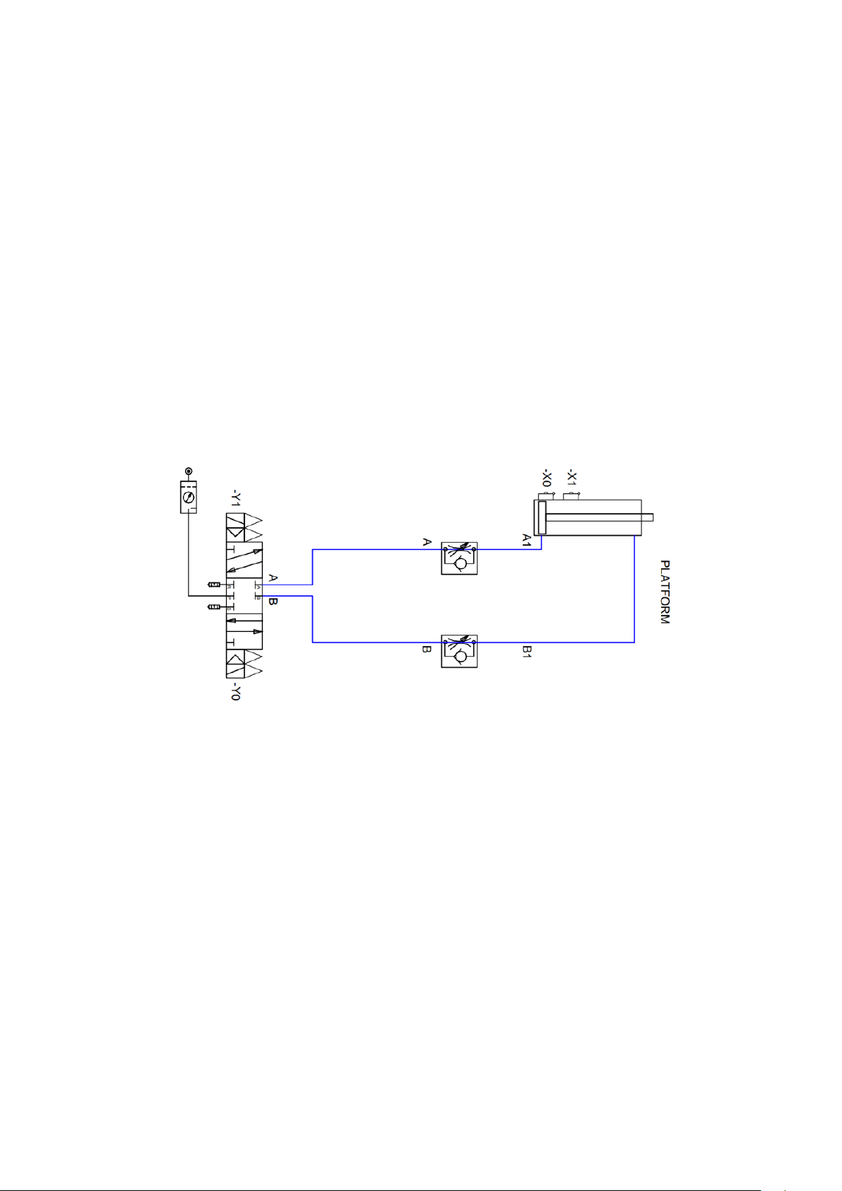
ADJUSTING THE SPEED OF THE PNEUMATIC
CYLINDER
(IF INCLUDED)
10
ULTRASONIC CLEANING SYSTEMS ULTRASONIC CLEANING SYSTEMS
MAINTENANCE
Maintenance of the machine should only be carried out by
CRYSTAL CLEAN personnel. If the machine requires fur-
ther cleaning or shortening service intervals, please contact
your CRYSTAL CLEAN delegation. Any incidents or break-
downs should only be repaired by a CRYSTAL CLEAN
sales and service representative.
CLEANING LIQUID
It is necessary to periodically replace the used cleaning
liquid. It may happen that particles deposited on the bottom
of the cleaning tub will clog transducers, resistance and
other components, thus causing losses in the quality and
intensity of cleaning and reduction of the life of the
transducers. This interval for water change depends on the
intensity of use of the machine, both in time and in the
degree of dirt of the parts to be cleaned.
IT IS RECOMMENDED TO CLEAN THE
TANK PERIODICALLY
ULTRASOUND EMITTERS
The surface of the emitter erodes after many years. It is
necessary to examine it with each change of water before
use. When it is seriously eroded, holes appear on the surface,
which in case of penetrating the plate will allow water to enter
the interior of the emitter and will generate a fault.
Clean periodically by taking advantage of water changes.
The inside of the tank is cleaned using a water hose.
It is necessary to use the cleaning products recommended
by CRYSTAL CLEAN , in order not to cause damage to
the parts to be cleaned or to the ultrasound equipment itself.
Each machine will use a product adapted to the specific
application that is needed. CRYSTAL CLEAN will supply
the data sheet of the products to be used.
IMPORTANT: NEVER clean them if they are at high
temperature. Allow to cool and rinse together with the
bottom of the tank. If you want to expedite the process,
empty the hot water tank while mixing with cold water
so that the temperature gradually drops. This is done to
avoid a sudden change of temperature in the emitters
(Ultrasound boxes).
GENERATORS
Clean it once a month with a compressed air gun using the
safety glasses. If the dirt that is generated at the site where
the equipment is located is extreme (eg suspension of
particles such as chip powder, paint suspension, polishing
powder in suspension, etc.). They will be cleaned more often.
DO NOT clean with organic solvents such as solvent,
alcohol, or kerosene since the paint coat of the generator
may deteriorate or even deform the plastic components of
the equipment.
Way of acting:
• Open the back of the unit. Remove the lters from the
generators (in the case of models with lters), located at the
rear. Blow with air gun (make sure no water gets out with air).
• Blow the generators.
• Mount the lters of the generators.
• Replace the rear panel that has been removed to access
the generator.
ELECTRICAL CABINET
Clean the inside of the cabinet with air gun every 1-3 months
depending on the accumulated dirt. If the work environment
is too dirty, do so at shorter intervals. Whenever the air gun is
used it is necessary to use the safety glasses.
HEATING ELEMENT
Check cleaning at each water change.
If it is covered by sludge, a fault can occur. It can be cleaned
using a water hose.
LEVEL PROBE (if included)
Check the cleaning of the level probe every water change.
Sludge or other types of dirt may be present in the probe
housing. Be sure to remove any items and clean using a
water hose.
SCREEN
Do not use with wet hands or chemical residues.
Clean with a cloth and mild soap when necessary.
Cleaning with other more aggressive chemicals can cause
irreparable damage to the screen.
PNEUMATICS (if included)
Bleed the regulator lter if necessary
Check that the air supply is free of moisture.
If moisture enters the pneumatic circuit, the solenoid valve
and cylinder can be damaged.
WATERFLOW SYSTEM (if included)
Cleaning the auxiliary tank with each change of water.
It is often impregnated with oil that in some cases is dried and
accumulated both in the bottom and in the extraction bowl.
Clean the lter inside the tank in turn. This can be unscrewed
to clean outside of the machine.
FILTERING SYSTEM (if included)
Verify the pump is operating properly taking advantage of the
water changes.
Clean the lter periodically using the drain valve.
Check that the lter bags are in good condition, not broken.
Check the gasket.
All these operations must be done at a temperature below
104 ° F.
Maintenance periods for standard cleaning:
•Cleaning liquid change: When poor or longer cleaning
is observed.
•Check surface emitter status: Each water change
•Emitters cleaning: Each water change.
•Generator cleaning: 1-3 months depending on
environmental conditions.
•Electrical cabinet cleaning: 1-3 months depending on
environmental conditions.
•Check heat resistance condition: Every change of water.
•Check level probe condition: Every change of water.
•Screen cleaning: When required.
•Purge air lter: When necessary (each case will be
different).
•Check air circuit humidity: Daily
•Auxiliary tank cleaning: Every change of water.

11
ULTRASONIC CLEANING SYSTEMS ULTRASONIC CLEANING SYSTEMS
POSSIBLE DISFUNCTIONS
1. No power:
-Check the power cord and plug.
-Check the switch and the main supply is possible.
-Check the fuse located on the power plug.
-Replace the fuse if necessary.
2. Indicators do not work.
- Call Service.
3. Ultrasonic cavitation weak:
-Clean the base of the tank of dust and particles.
-Change the water level.
-Empty the tank and rell with clean water.
4. Touch screen (if included)
1. Touch screen does not work.
- Call Service.
2. A warning of low battery appears on the screen.
- Change the battery.
5. High temperature warning.
- In the case of the equipment exceeds 90ºC / 194ºF,
ultrasounds and the heating elements will stop. For them
to operate again, the temperature should drop at least 5.
This may happend whe the lid is not open for a long time
due to the transducer boxes generate heat that can not
dissipate.
6. Communication failure.
- Call Service.
7. Generator (if included)
1. It does not emit US.
- Check that the partial automatic of the ultrasounds is on.
- Check for voltage to the generator.
- If any of the above is correct, call Service.
8. Heating element
1. It does not heat.
- Check that the partial automatic is on.
- Check that the setpoint temperature is correct on the
display.
- Check that temperature sensor is in touch with the tank.
9. Pneumatic system (if included)
1. No aire in the system.
- Check that the external air system works.
- Check that the tap of the lter regulator is the right one for
the working pressure.
- Check that the tap is opened.
- Check the circuit for leacks.
- Check that the ow regulator is in the correct position.
10. Movement function (if included)
1. Movement function failure.
- Check that the cylinder sensors switch on the LED.
- Check that the ow regulator is in the correct position and
cot completely closed.
- Any other disfunction, call Service.
11. WFS and lter (if included)
1. No water movement is appreciated in the system.
- Check that the supply voltage reaches the pump.
- The pump is not working. Call Service.
- Check that the system is clean both at the suction area of
the auxiliary the tank, and at the intake of the main the tank.
- Check That the rotor of the pump is not blocked.
12. Transducer boxes (if included)
.
1. They don’t emit.
- Call Service.
2. They don’t clean properly.
- Call Service.
SITUATIONS AND PLACES WHERE THE MACHINE CAN
NOT BE USED.
Never use the machine outdoors or in areas with an
excessively dirty environment. In case you can not avoid
working in dirty environment, proceed to maintenance works
more frequently.

12
ULTRASONIC CLEANING SYSTEMS ULTRASONIC CLEANING SYSTEMS
TECHNICAL SPECIFICATIONS
1. Power Supply: 230V Monophase + Neutral + Earth.
2. Capacity: 220 liters / 60 gallons
3. Tank built in AISI 304, 2mm / 0,078”. thick, Stainless-
Steel.
4. Integrated auxiliary tank for lubricants and oil separation,
with 40 liters / 10 gal. of capacity.
5. 1 ultrasonic generator with 2000Wp (4000Wp-p) total
output power. Working frecuency: 40 KHz sweep system
±2%.
6. 1 submersible emitter, 2000Wp. Working frecuency: 40
KHz. The emitter is equipped with 34 PZT (lead zirconate
titanate) transducers with an aluminum alloy body. The
emitters are made of 2.5mm / 0,098” INOX AISI 316 steel
thick, with a mirror polished finish.
7. 1 heating element 3750 W.
8. Outside panel in 1mm / 0,039” thick fingerprint-resistant
steel.
9. ½” BSP auxiliary tank drain draining ball valve, and 1”
BSP draining ball valve.
10. 20mm / 0,78” thick K-Flex Duct Net thermal-acoustic
insulation.
11. Pneumatic lifting platform for loading, oscilating
movement and unloading with a capacity of
200Kg /440Lbs. Air requirements is 85 PSI / Reads 6 bar
on Regulator
12. Insulated tank cover in Stainless-Steel.
13. Air blow-gun for drying parts.
14. Compressed air connection: Ø 8mm / Ø 0,314”
15. 4.3” Touch screen, functional and intuitive access to
ultrasound time setting, temperature and peripheric
or optional systems; and programmable with weekly
calendar. 6 outputs & 8 inputs temperature module PLC.
16. DIMENSIONS (large x wide x high):
- Internal: 760 x 520 x 590 mm / 29.92 x 20.47 x 23.23 inch.
-Useful: 730 x 465 x 350 mm / 28.74 x 18.31 x 14.96 inch.
- External: 1330 x 930 x 1590 mm / 52.36 x 36.62 x 62.60 inch.
17. Filtration system for waste and sludge (optional).
The noise emissions in this machine are less than 65dB.
There are two regulators, the upper one controls the speed
of raising the platform while the lower one controls the speed
of lowering.
The maximum weight that can be lifted with this machine is
indicated in this area.
REGISTERS
At the rear of the machine: access to the heating element,
solenoid valve, temperature sensor, cylinder, cylinder
detector..
At the front of the machine: access to the pump.
On the left side of the machine: electrical cabinet.
On the rigth side of the machine: ultrasonic generator.
ULTRASONIC CLEANING SYSTEMS ULTRASONIC CLEANING SYSTEMS 13
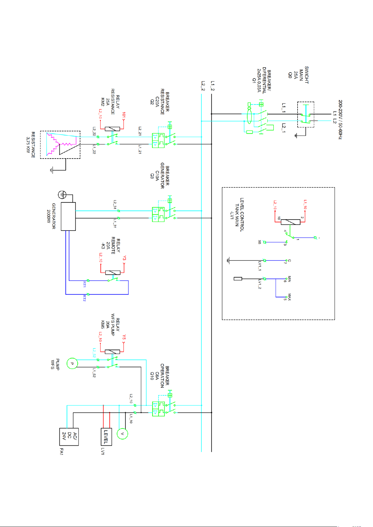
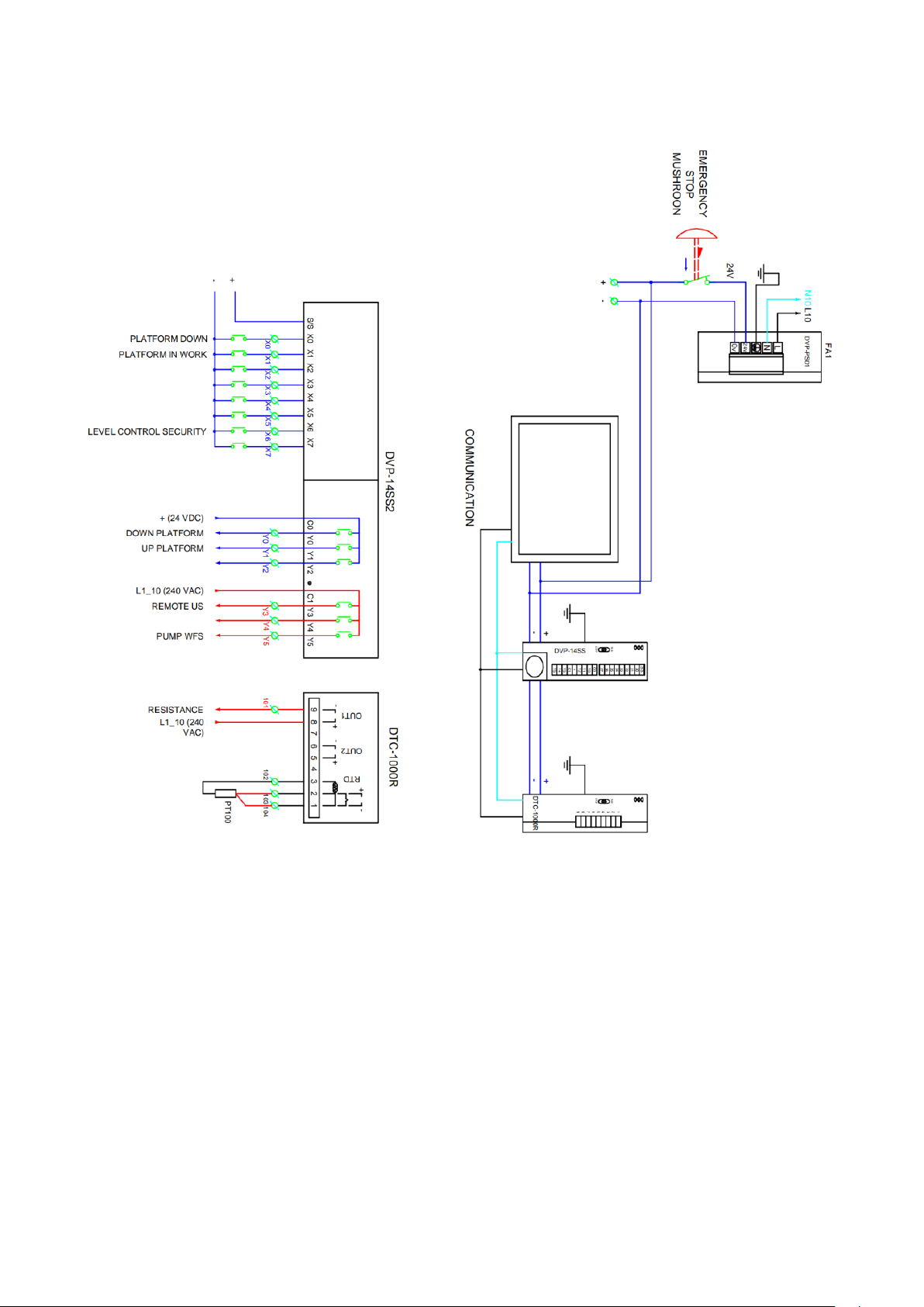
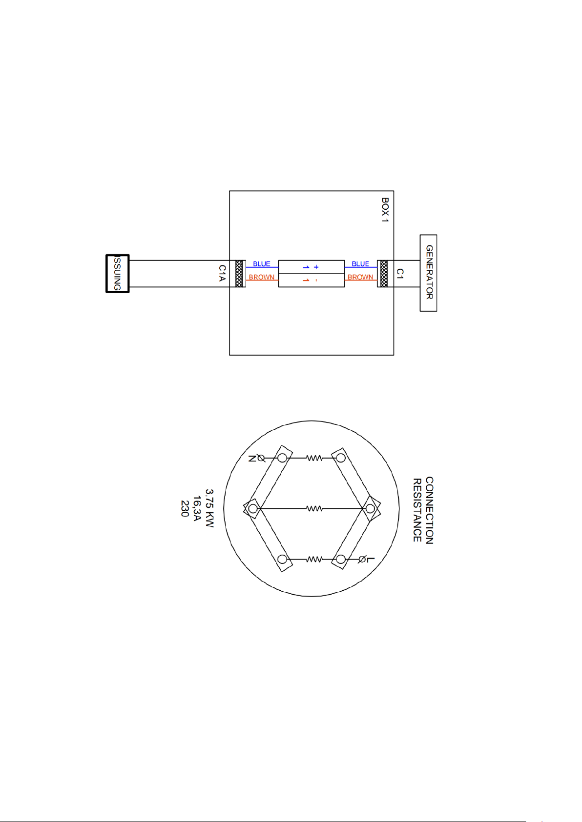
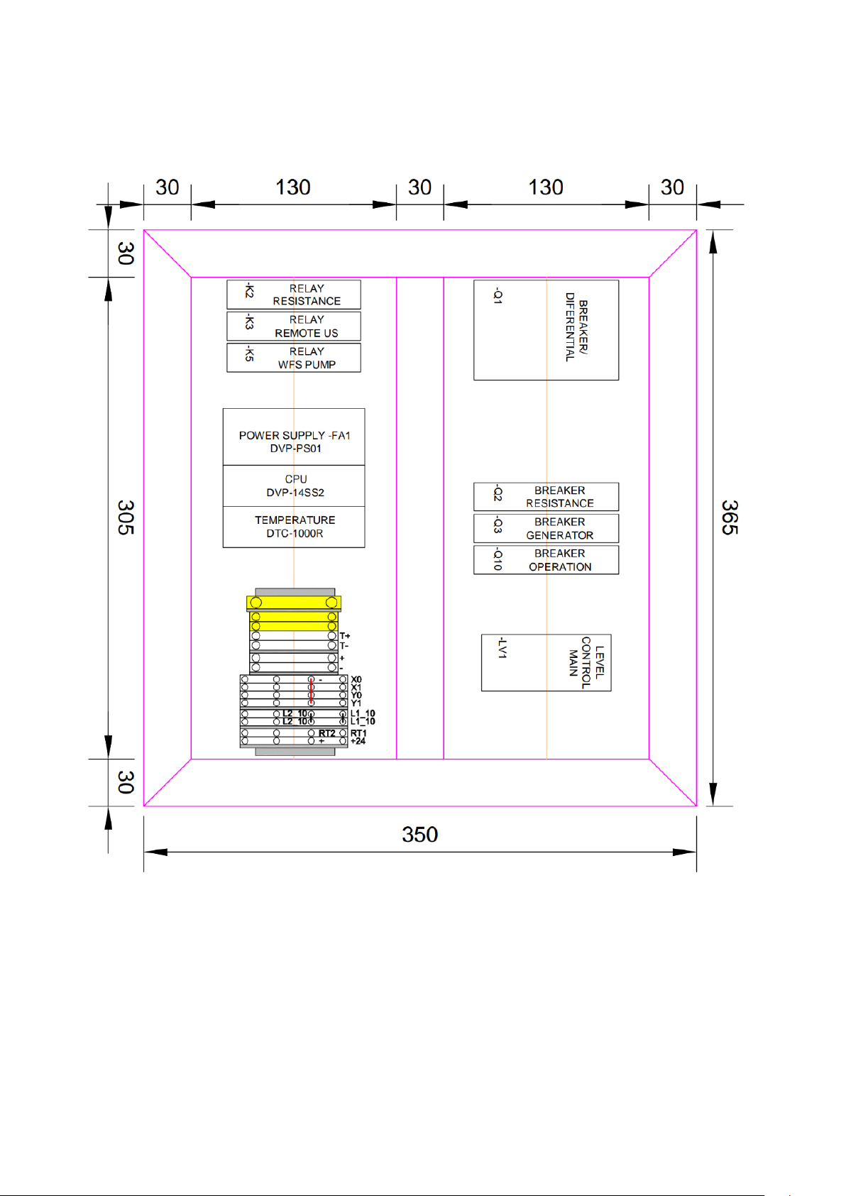
ELECTRICAL AND PNEUMATICS SCHEMES
14
ULTRASONIC CLEANING SYSTEMS ULTRASONIC CLEANING SYSTEMS
ULTRASONIC CLEANING SYSTEMS ULTRASONIC CLEANING SYSTEMS 15
16
ULTRASONIC CLEANING SYSTEMS ULTRASONIC CLEANING SYSTEMS
ULTRASONIC CLEANING SYSTEMS ULTRASONIC CLEANING SYSTEMS 17
18
ULTRASONIC CLEANING SYSTEMS ULTRASONIC CLEANING SYSTEMS
RISK ASSESMENT
This equipment has built-in ultrasound emitters inside the tanks. Ultrasound are acoustic waves whose frequency is
above the hearing capacity of the human ear (approximately 20,000 Hz). Ultrasonic cleaning is a method that uses ultrasounds
(generally 15-2000 kHz) and an appropriate cleaning solution. The ultrasonic frequency in this type of work is low.
The health effects of ultrasound, as included in the Technical Note of Prevention 205 are the following:
By contact: mainly manifested in the hands, in cleaning and degreasing operations. There is no such exposure, since the
transmission medium is aqueous, that is, the water acts as a shield, with which the transmission of ultrasounds is practically
non-existent.
By air: same as the previous point.
Every cleaning operation with this equipment is made with the lid closed, so there is no exposure to ultrasound.
In case of auditory discomfort it would be advisable to use adequate protection (plugs, etc.), although the noise
emission values are below the maximum admissible.
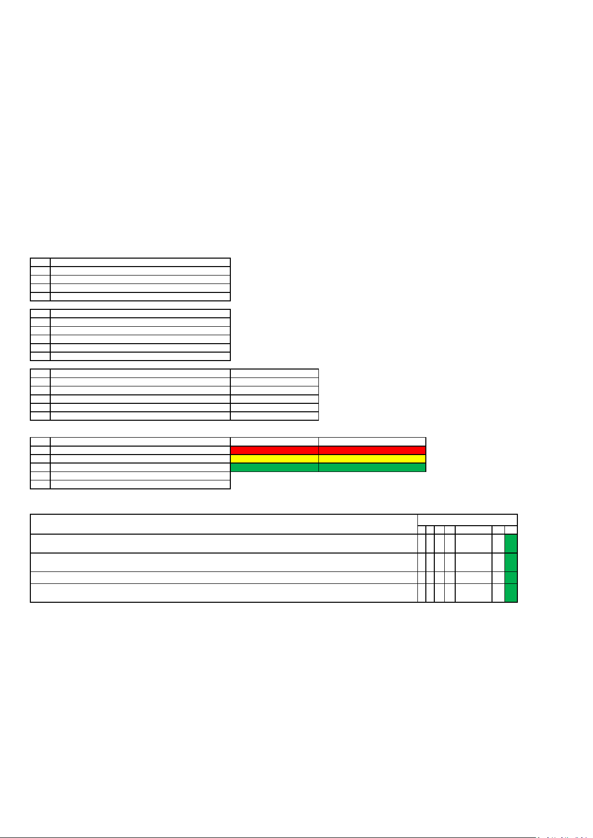
Risks that could not be eliminated are analyzed below:
CLASS SEVERITY (S)
1Minor injuries. 3 Days maximum of sick leave. First aids.
2Reversible damages. Between 3 and 30 days of sick leave.
3Permanent damages. More than 30 days of sick leave.
4Death. Permanent disability.
CLASS FREQUENCY (Fr)
2 Never / Almost never / More than 1 year
3Rarely / More than two weeks and up to 1 year
4Occasionally / More than 1 day and up to a week
5Regularly / More than one hour and up to a day
6Often / Less than one hour
CLASS PROBABILITY (Pr) Avoidable (Av)
1Unlikely, not known or in any case Avoidable
2Unlikely to occur
3Posible Likely avoidable
4Probable
5Frequently Impossible to be avoided
NGrade (N1) Class
14-15 56-8
11-13 44-5
8-10 31-3
5-7 2
3-4 1
SFr Pr Av N=Fr+Pr+Av N1 (P)
1 2 1 1 4 1 1
1 2 1 1 4 1 1
1 2 1 1 4 1 1
1 2 1 1 4 1 1
In the user manual it is indicated that the piece, once cleaned, is left in the basket until the liquid is drained.
Risk generated by the transfer of flammable liquids to the cleaning liquid. The users manual indicates that it is necessary to make sure that the part to
be cleaned is free of flammable liquids.
Risk assesment
Risk profile (P)=S+N1-1
High risk. Correction neded
Medium risk
Low risk
RISK DESCRIPTION. CORRECTIVE ACTION
Risk of thermal contact with hot parts of the machine, the cleaned part or the cleaning liquid. The risk is duly signposted on the machine at the exit of
the cleaning liquid and the use of heat protection gloves is indicated in the users manual.
Risk of contact with chemical products (cleaning fluid). In the users manual, is indicated that it should be considered the cleaning products safety data
sheets and the use of chemical protective gloves.
Table of contents
Other Crystal Clean Cleaning Equipment manuals

Popular Cleaning Equipment manuals by other brands


Garten Meister
Garten Meister 94 60 24 Original instructions

Good Way
Good Way VAC-EX-120-9-SS Operation and maintenance manual

Drieaz
Drieaz DriForce XL owner's manual

e.ziclean
e.ziclean Cyclosteam P310 manual

Flow Medic
Flow Medic U-sonic instruction manual

Omegasonics
Omegasonics PowerLift 4560 Operation & instruction manual