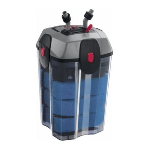
Inlet
Outlet
Connecting Tubing into Filter (Figs 3, 4, and 5)
PLASTIC TUBING
• Cut tube ends square and straight. Do not deform tube (i.e., cause tube to compress its diameter so it is
no longer round).
1. Remove red end caps from unit’s water inlet/outlet connections.
Changing Filters (Fig 6)
NOTE:THIS MEGA UNDERSINK SYSTEM CONTAINS CARTRIDGES WHICH MUST BE REPLACED AT REGULAR
INTERVALS TO MAINTAIN PROPER PERFORMANCE. USE ONLY FACTORY APPROVED CARTRIDGES.
• Release any pressure in the line by turning on the cold- and hot-water faucets.
water.
(Cartridges may be recycled. Visit www.crystalquest.com/crystal quest
policies.htm under Preventive Routine Mintenance instructions.)
you're working on.)
directional arrow on the cartridge which indicates “This End Towards Cap”.
• Check O-ring(s). Lubicate with cooking oil if needed. Position O-ring(s) properly in the groove of the sump and tighten
by turning it clockwise. Do not overtighten. Do not cross-thread at the sump or inlet/outlet ports. If cross-threaded, do
not put or keep unit in service.
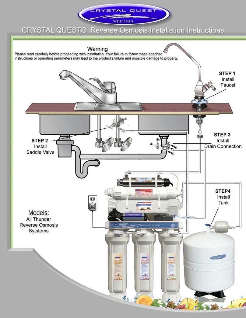
STEP 2 – Install the Saddle (Feedwater) Valve and Tubing (Fig 2)
CHOOSE THE VALVE LOCATION
• Choose a location for the valve that is easily accessible. It is best to connect into the side of a vertical water pipe. When it is necessary to connect into a horizontal water
• Disconnect the cold water supply line. Attach and tighten the saddle valve connector assembly, being careful not to pinch or crimp any tubing or water supply line while
NOTE: The saddle valve clamps onto hard tubing or pipe. It will make its own hole in copper tubing but not in iron or brass.
For brass or galvanized iron pipe, drill a 1/4” hole in pipe before mounting saddle valve. If possible, use a hand or cordless drill
when drilling water pipe. If using an electric drill, be sure that drill, cord and outlet are all properly grounded.
NOTE: If water supply line is soft tubing, it is recommended to use aT-valve installation.
NOTE: Do not turn handle before installing or while installing saddle valve.To prevent damage to piercing needle,make sure
NOTE:
1. Hold backplate against tube.
2. Hold saddle valve against tubing in a position directly opposite backplate.
3. Tighten screw enough so saddle valve and backplate are held securely against tube.
CONNECT SOURCE WATER FEED TUBING TO VALVE BODY USING COMPRESSION FITTING
1. Slide nut and sleeve onto tubing (in that order).
2. Install insert into tubing.
3. Install tubing with insert and sleeve into valve body.
4. Thread compression nut onto valve body. Tighten.
CAUTION: When the supply line is pierced, the valve should be closed. Do not open valve until system is activated. Turn on
cold water supply. Check saddle-tapping valve installation for leaks. Allow water to run from faucet for a few
minutes to clear any debris in the line caused by installation.
NOTE:
Tightening
Screw
Reversible
Plate
Compression
Nut
Tubing
Cold water
supply line
Sleeve
Insert
Valve
Handle
Valve
Body
CONNECT USING QUICK-CONNECT
FITTINGS
• Fittings consist of three parts: a body, collet, and
a locking clip. Make sure outer surface of tube is
clear of marks or scratches for a length equal to
twice tube diameter. This allows O-ring to seat
properly against tube.
• Remove locking clip from body collet (A).
• Push tube through collet into body until it seats
clip around the collet. Not replacing the locking
damage (A, B).
BODY
LOCKING CLIP
COLLET
TUBE
A
B
REMOVE FITTINGS
•
locking clip.
• Push and hold collet against body (ring of the
tube out.
• To reinsert a tube, cut 1/2” of tube from the end.
This will help prevent leaking. Replace the locking
clip around the collet.
CONNECT USING COMPRESSION
FITTINGS
• Slide compression nut over the end of
tubing.
• Connect compression nut to compression
adapter and tighten the compression nut
securely.
Fig 3
Fig 2
Fig 4A Fig 4B Fig 5
Fig 6
Sump
Sump
Wrench
Mounting the Faucet:
Disassemble hardware from the threaded
nipple, except for chrome base plates and
rubber washers. (Rubber washers may be
replaced with a bead of plumber's putty
for neater appearance.) Feed the threaded
nipple through sink or counter mounting
hole and position the faucet. From below
sink or counter, assemble the white spacer
toward air gap). After checking faucet ori-
entation, tighten with a wrench until secure
(Fig 1).
Important Notice
licensed plumber. Not using the service
of a plumber will void warranty. Crystal
for systems improperly installed or those
licensed plumber.
Porcelain, Enamel, Ceramic on Metal or Cast Iron:
Precautions must be taken to penetrate the porcelain through to the metal
base and prevent it from chipping or scratching.
Tools required:
• Variable speed drill • Relton porcelain cutter tool set (7/8" or
• Plumber’s putty alternative size, 9/16”)
Procedures:
1. Mark the center for the 7/8" hole.
lubricate carbide drill bit.
3. Carefully drill pilot hole through all layers (use light pressure and slow
speed).
4. Insert pilot tip of spring-loaded porcelain cutter into pilot hole.
5. Drill porcelain/enamel using spring-loaded porcelain cutter, making
certain a complete ring has been cut through the porcelain/enamel to the
metal base.
6. Cut away the inner porcelain/enamel disc down to the base metal. Make
certain the cutter does not touch outer rim of the cut porcelain/enamel.
Continue with this bit to cut through metal until sink has been completely
penetrated.
Note: Always use sharpened porcelain cutter to eliminate chips and
cracks.
Stainless Steel Sinks:
Recommended tools:
• Center punch
• Variable speed drill
• High speed drill bits
• Greenlee chassis punch 7/8" (9/16" for
non air gap faucets)
• Protective gloves and eye protectors
Procedures:
1. Center punch small indent for hole.
2. Drill the required pilot hole.
3. Set-up the chassis punch per
instructions and tighten nut to cut
the desired hole size.
• 1-1/4" wood bit
• Household bleach (liquid)
• Crescent wrench
• Air pump (hand)
• Safety glasses
• 3/8” variable speed electric drill, 1/8” and 1/2” bits
• 1-1/4” porcelain hole cutter (if hole for second faucet is not provided)
• Plastic anchors and screws
• Plastic tube cutter
• Air pressure gauge (low pressure)
• Pliers
Tools and Material Recommended for Installation
Easy To Install
STEP 1 – Install the Faucet (Fig 1)
Faucet should be placed near the sink where drinking/cooking water is normally required.
mount the faucet if an existing hole for a second faucet is not available. The mounting thickness should not exceed 1-1/4". If
the sink has a sprayer, it may be disconnected for faucet installation. A pipe cap or plug will be necessary to seal the sprayer
connection. If making the faucet mounting hole (if sprayer or second hole is not used), check to make sure the drill does
not exceeding 1-1/4" in thickness). Drill the required pilot hole of the chassis punch and tighten nut to cut the desired hole
size. Clean up sharp edges. The faucet should be positioned so it empties into the sink and the spout swivels freely for
convenience. If sink has a hole that can accommodate the faucet, no drilling is required. Proceed with mounting the faucet.
Preparing for Installation
to follow them could cause serious property damage.
• Inspect the carton and unit for evidence of rough handling and concealed damages. If
that all installation parts are present, which includes the unit, faucet, installation hardware
contact customer support for replacement parts at (800) 934-0051.
All drawings, pictures, colors, and sizes are approximate for illustration purposes only
and may not reect the end product. All models are subject to change without notice.
Mega 1000
6-Stage Filtration
CQE-US-00303
CQE-US-00304
CQE-US-00305
Mega 2000
7-Stage Filtration
CQE-US-00306
CQE-US-00307
CQE-US-00308
Mega 3000
8-Stage Filtration
CQE-US-00309
CQE-US-00310
CQE-US-00311
Important!
undersink units.
page 2page 3
WaterSimplyPure.com 859-336-3246


