Crystal Vision Hardware installation
FTX HD User Manual R1.0 6 13/08/2007
2.1 Universal rear connectors
When using the RM31 single height rear connector, the 4U Indigo 4 frame will house up
to 24 modules and three power supplies, the 2U Indigo 2 frame will house up to 12
modules and dual power supplies, while the 1U Indigo 1 frame will house six modules
and a single or dual power supply. The 1U desktop box will not currently accept the
Crystal Vision optical modules.
The Indigo frames have hinged front panels giving access to the PSU and all modules.
The universal frame wiring system allows any of the interface modules to be fitted in (1)
all positions with the use of removable rear modules.
(1) Due to height restraints, there are restrictions when mixing optical modules with other Crystal Vision
modules.
Loading restrictions
The FTX HD can be loaded into any slot position of compatible frames but due to its
extra height it is not possible to place cards from the Crystal Vision Standard Definition
video or audio range directly above it in certain positions. HD cards do not share this
restriction.
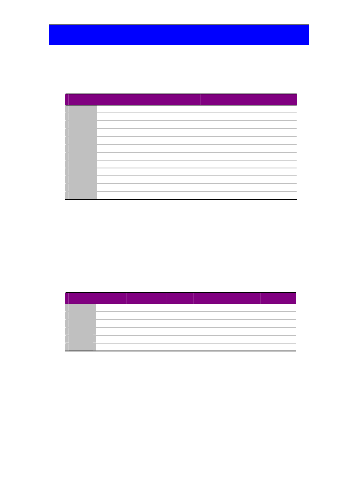
Frame type
xxxxxxxx xxxxxxxx xxxxxxxx
Optical module Optical module Optical module
xxxxxxxx xxxxxxxx xxxxxxxx
Indigo 4
Optical module Optical module Optical module
xxxxxxxx xxxxxxxx xxxxxxxx
Indigo 2 Optical module Optical module Optical module
xxxxxxxx xxxxxxxx xxxxxxxx
Indigo 1 Optical module Optical module Optical module
Optical cards loaded in these slots will not allow Standard Definition or audio cards to
be fitted in the slots immediately above.
Rear module connections with RM31
RM31 fits in all frames Description
RM31
•24 modules in 4U, 12
modules in 2U & six in 1U
•All frame slots can be used
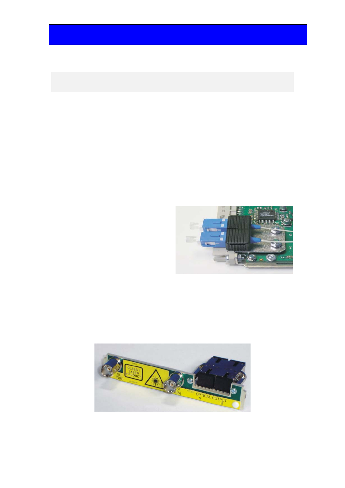
BNC I/O assignment
Optical Input (B) Optical serial digital video output (B)
Optical Input (A) Optical serial digital video output (A)
SDI IN(A) Channel A HD/SD Serial digital input
SDI IN(B) Channel B HD/SD Serial digital input