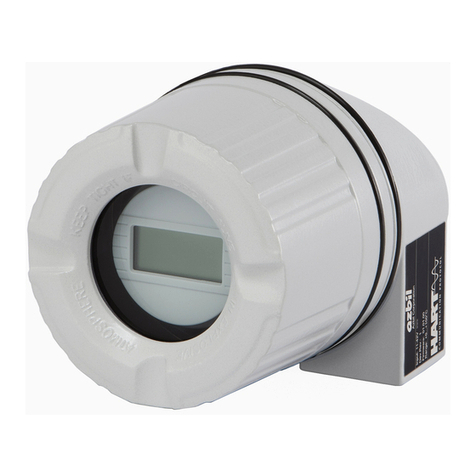
Azbil ATT082 Instructions for use

CM2-ATT082-2003
Advanced Temperature Transmitter
with HART protocol
Model ATT082
Functional Safety Manual

NOTICE
While the information in this manual is presented in good faith and
believed to be accurate, Azbil Corporation disclaims any implied
warranty of merchantability or fitness for a particular purpose and
makes no express warranty except as may be stated in its written
agreement with and for its customer.
In no event shall Azbil Corporation be liable to anyone for any indirect,
special or consequential damages. is information and specications
in this document are subject to change without notice.
© 2016 Azbil Corporation All Rights Reserved.

Safety
Precautions for Use
For safe use of the product, the following symbols are used in this manual.
WARNING Warnings are indicated when mishandling the product might
result in the death or serious injury of the user.
CAUTION Cautions are indicated when mishandling the product might
result in minor injury to the user or damage to property.
■In describing the product, this manual uses the icons and conventions listed below.
Use caution when handling the product.
The indicated action is prohibited.
Be sure to follow the indicated instructions.
Handling Precautions:
Handling Precautions indicate items that the user should pay attention to when handling
the ATT.
To use this product correctly and safely, always observe the following precautions.
We are not responsible for damage or injury caused by the use of the product in violation of these precautions.
Handling Precautions for This Product
Installation Precautions
WARNING
When installing, use proper fittings and proper tightening torque for connections to the
process and to the exhaust. Gas leakage is dangerous because process gas and calibration
gas are flammable. Please refer to the leak check instructions in this manual and verify
that there is no gas leakage.
Do not use the product except at the rated pressure, specified connection standards, and
rated temperature. Use under other circumstances might cause damage that leads to a
serious accident.
For wiring work in an explosion-proof area, follow the work method stated in the
explosion-proof policy.
i

ii
CAUTION
After installation, do not step or stand on this unit. Doing so may damage the device or
cause injury.
Bumping the glass of the display with a tool may cause damage or injury. Be careful.
Install the device correctly. Incorrect or incomplete installation will cause output errors
and violation of regulations.
This product is quite heavy. Protect your feet with safety shoes when working.
Do not subject the product to shock or impact.
Wiring Precautions
WARNING
Do not do wiring work with wet hands or while electricity is being supplied to the product.
There is a danger of electric shock. When working, keep hands dry or wear gloves, and
turn off the power.
CAUTION
When wiring, check the specifications carefully and make sure to wire correctly. Incorrect
wiring can cause device damage or malfunction.
Supply electric power correctly according to the specifications. Supplying power that
differs from the specifications can damage the device.
Use a DC power supply that has overload protection.
Maintenance Precautions
WARNING
When removing this device for maintenance, be careful of residual pressure or residual
process gas. Leakage of process gas is dangerous.
When working on the vent, check its direction so that people do not come into contact
with vented gas. There is a danger of burns or other physical harm.
When the device is being used in an explosion-proof area, do not open the cover.
Opening the cover may cause an explosion.
CAUTION
This product was kept under carefully controlled conditions until it was shipped. Never try
to modify this device. Doing so could damage it.

iii
Certicate

iv
Table of Contents
Chapter 1. SIL key figures. . . . . . . . . . . . . . . . . . . . . . . . . . . . . . . . . . . . . . . . . . . . . . . . . . . . . . . . . .1
Chapter 2. Permitted devices types . . . . . . . . . . . . . . . . . . . . . . . . . . . . . . . . . . . . . . . . . . . . . . . .3
Chapter 3. Safety functions . . . . . . . . . . . . . . . . . . . . . . . . . . . . . . . . . . . . . . . . . . . . . . . . . . . . . . . .5
3-1. Definition of the safety function. . . . . . . . . . . . . . . . . . . . . . . . . . . . . . . . . . . . . . . . . . . . . . . . . . . . . . . . . 5
3-1-1. Safety-related output signal. . . . . . . . . . . . . . . . . . . . . . . . . . . . . . . . . . . . . . . . . . . . . . . . . . . . . . 5
3-1-2. Dangerous undetected failures in this scenario . . . . . . . . . . . . . . . . . . . . . . . . . . . . . . . . . . . 5
3-1-3. Limit value monitoring. . . . . . . . . . . . . . . . . . . . . . . . . . . . . . . . . . . . . . . . . . . . . . . . . . . . . . . . . . . 5
3-1-4. Safe measurement . . . . . . . . . . . . . . . . . . . . . . . . . . . . . . . . . . . . . . . . . . . . . . . . . . . . . . . . . . . . . . . 6
3-2. Restrictions for use in safety-related applications . . . . . . . . . . . . . . . . . . . . . . . . . . . . . . . . . . . . . . . . 7
3-3. Safety measured error . . . . . . . . . . . . . . . . . . . . . . . . . . . . . . . . . . . . . . . . . . . . . . . . . . . . . . . . . . . . . . . . . . 8
3-4. Restrictions of the device specifications for the safety operation . . . . . . . . . . . . . . . . . . . . . . . .11
Chapter 4. Use in protective systems. . . . . . . . . . . . . . . . . . . . . . . . . . . . . . . . . . . . . . . . . . . . . 13
4-1. Behavior of device during operation and in case of error . . . . . . . . . . . . . . . . . . . . . . . . . . . . . . . .13
4-1-1. Behavior of device during power-up. . . . . . . . . . . . . . . . . . . . . . . . . . . . . . . . . . . . . . . . . . . . .13
4-1-2. Behavior of device during normal operation (SIL measuring mode) . . . . . . . . . . . . . . .13
4-1-3. Device behavior in safety function demand mode . . . . . . . . . . . . . . . . . . . . . . . . . . . . . . .13
4-1-4. Safe states . . . . . . . . . . . . . . . . . . . . . . . . . . . . . . . . . . . . . . . . . . . . . . . . . . . . . . . . . . . . . . . . . . . . . .13
4-1-5. Behavior of device in event of alarms and warnings . . . . . . . . . . . . . . . . . . . . . . . . . . . . . .14
4-2. Parameter configuration for safety-related applications. . . . . . . . . . . . . . . . . . . . . . . . . . . . . . . . .15
4-3. Commissioning test and proof testing. . . . . . . . . . . . . . . . . . . . . . . . . . . . . . . . . . . . . . . . . . . . . . . . . .21
4-3-1. Proof testing the safety function. . . . . . . . . . . . . . . . . . . . . . . . . . . . . . . . . . . . . . . . . . . . . . . . .21
4-3-2. Transmitter commissioning or proof test . . . . . . . . . . . . . . . . . . . . . . . . . . . . . . . . . . . . . . . .22
Chapter 5. Life cycle. . . . . . . . . . . . . . . . . . . . . . . . . . . . . . . . . . . . . . . . . . . . . . . . . . . . . . . . . . . . . 27
5-1. Requirements for personnel . . . . . . . . . . . . . . . . . . . . . . . . . . . . . . . . . . . . . . . . . . . . . . . . . . . . . . . . . . .27
5-2. Installation . . . . . . . . . . . . . . . . . . . . . . . . . . . . . . . . . . . . . . . . . . . . . . . . . . . . . . . . . . . . . . . . . . . . . . . . . . . .27
5-3. Commissioning. . . . . . . . . . . . . . . . . . . . . . . . . . . . . . . . . . . . . . . . . . . . . . . . . . . . . . . . . . . . . . . . . . . . . . . .27
5-4. Operation . . . . . . . . . . . . . . . . . . . . . . . . . . . . . . . . . . . . . . . . . . . . . . . . . . . . . . . . . . . . . . . . . . . . . . . . . . . . .27
5-5. Maintenance . . . . . . . . . . . . . . . . . . . . . . . . . . . . . . . . . . . . . . . . . . . . . . . . . . . . . . . . . . . . . . . . . . . . . . . . . .27
5-6. Repair28
5-7. Modification. . . . . . . . . . . . . . . . . . . . . . . . . . . . . . . . . . . . . . . . . . . . . . . . . . . . . . . . . . . . . . . . . . . . . . . . . . .28
Chapter 6. Appendix . . . . . . . . . . . . . . . . . . . . . . . . . . . . . . . . . . . . . . . . . . . . . . . . . . . . . . . . . . . . 29
6-1. Structure of the measuring system . . . . . . . . . . . . . . . . . . . . . . . . . . . . . . . . . . . . . . . . . . . . . . . . . . . . .29
6-1-1. Measurement function. . . . . . . . . . . . . . . . . . . . . . . . . . . . . . . . . . . . . . . . . . . . . . . . . . . . . . . . . .30
6-2. Commissioning or proof test report . . . . . . . . . . . . . . . . . . . . . . . . . . . . . . . . . . . . . . . . . . . . . . . . . . . .32
6-2-1. Parameter settings for safe parameterization . . . . . . . . . . . . . . . . . . . . . . . . . . . . . . . . . . . .34
6-3. Other36
6-3-1. Parameters and default settings for safe parameterization. . . . . . . . . . . . . . . . . . . . . . . .36
6-3-2. Safe HART® . . . . . . . . . . . . . . . . . . . . . . . . . . . . . . . . . . . . . . . . . . . . . . . . . . . . . . . . . . . . . . . . . . . . .40
6-3-3. Use as a safe measuring system . . . . . . . . . . . . . . . . . . . . . . . . . . . . . . . . . . . . . . . . . . . . . . . . .41
6-3-4. Assignment of code numbers to parameters. . . . . . . . . . . . . . . . . . . . . . . . . . . . . . . . . . . . .43
1
Chapter 1. SIL key figures
General
Safety-related output signal 4...20mA
Fault current 3.58 mA
Process variable/function Temperature, voltage, resistance
Safety function(s) min., max., range
Device type acc. to IEC 61508-2
☐
Type A
☑
Type B
Operating mode
☑
Low Demand Mode
☑
High Demand
☐
Continuous Mode
Valid Hardware-Version Head transmitter: 01.00.06 or higher
DIN Rail transmitter: 01.00.04 or higher
Valid Software-Version 01.01.08 or higher (Dev.Rev.:2 or higher)
Type of evaluation
(check only one box)
☑
Complete HW/SW evaluation parallel to development incl.
FMEDA and change request acc. to IEC 61508-2, 3
☐
Evaluation of “Proven-in-use“ performance for HW/SW incl. FMEDA
and change request acc. to IEC 61508-2, 3
☐
Evaluation of HW/SW field data to verify “prior use“ acc. to IEC
61511
☐
Evaluation by FMEDA acc. to IEC61508-2 for devices w/o software
Evaluation through TÜV SÜD Product Service GmbH, Germany
Test documents development documents, test reports, data sheets
SIL - Integrity
Systematic safety integrity
☐
SIL 2 capable
☑
SIL 3 capable
Hardware safety integrity Single channel use (HFT = 0)
☑
SIL 2 capable
☐
SIL 3 capable
Multi-channel use (HFT ≥ 1)
☐
SIL 2 capable
☑
SIL 3 capable
FMEDA
Safety function min., max., range
λDU1) 40 FIT
λDD1) 258 FIT
λSU1) 129 FIT
λSD1) 4 FIT
SFF - Safe Failure Fraction 91%
PFDavg T1 = 1 year 2) (single channel architecture) 1.75 · 10-4
PFDavg T1 = 5 years 2) (single channel architecture) 8.76 · 10-4
PFH 4.0 · 10-8 · 1/h
PTC 3) 96%
MTBF 4) 71 years
Diagnostic test interval 5) 32 min
Fault reaction time 6) < 10.7 s
Process safety time 7) 53 h
Declaration
☑
Our internal company quality management system ensures information on safety-related systematic faults
which become evident in the future
1) FIT = Failure In Time, Number of failures per 109h
2) Valid for average ambient temperature up to +40 °C (+104 °F)
For continuous operation at ambient temperature close to +60 °C (+140 °F), a factor of 2.1 should be applied
3) PTC = Proof Test Coverage
4) MTBF (Mean time between failures) is the predicted elapsed time between inherent failures of a system during operation
in accordance to Siemens SN29500
5) All diagnostic functions are performed at least once within the Diagnostic test interval
6) Maximum time between error recognition and error response
7) The Process safety time is: Diagnostic test interval x 100 (calculated acc. to IEC 61508)

2
Useful lifetime of electrical components:
The established failure rates of electrical components apply within the useful lifetime as per
IEC 61508-2:2010 section 7.4.9.5 note 3.

3
Chapter 2. Permitted devices types
The details pertaining to functional safety in this manual relate to the device versions listed
below and are valid as of the specified firmware and hardware versions. Unless otherwise
specified, all subsequent versions can also be used for safety instrumented systems.
A modification process according to IEC 61508 is applied for any device modifications. Valid
device versions for safety-related use:
Feature Designation Version
010 Approval All
... ... ...
590 Additional approval LA
... ... ...
Order code:
↑
A0026614
The full order code is saved electronically in the
device. It is shortened on the nameplate due to
space limitations.
Valid firmware version as of 01.01.07
Valid hardware version
(electronics)
as of 01.00.06
Valid device drivers DTM as of version 1.0.2.1
DD as of revision 03
ATT082 x x x x x x x x x x x x x x x x xLA+

4
1
TAGXXXXXXXXXXX
TAGXXXXXXXXXXX
1 SIL symbol
Note: SIL certified devices are marked with the SIL symbol on the nameplate.

5
Chapter 3. Safety functions
3-1. Definition of the safety function
Permitted safety functions of the device are:
Limit value monitoring
Safe measurement
3-1-1. Safety-related output signal
The safety-related signal of the device is the analog output signal 4 to 20 mA according to the
NAMUR NE43. All safety precautions refer to this signal exclusively.
The safety-related output signal will be relayed to a downstream logic unit (e.g. PLC, limit
signal switch) where it is monitored on:
ascertain whether it exceeds or drops below predefined limit value.
occuring an error, e. g. error current (≤ 3.6 mA, ≥ 21 mA, cable open circuit or short circuit
of the signal wires).
Note: In the SIL mode the transmitter cannot be configured for inverse value display at the
current output.
3-1-2. Dangerous undetected failures in this scenario
An incorrect output signal that deviates from the value specified in this functional safety
manual but is still in the range of 4 to 20 mA, is considered a dangerous, undetected failure.
(Refer to page 7)
3-1-3. Limit value monitoring
This safety function provides the monitoring of the measured value. In the SIL mode, an error
current is output in the event of a measurement outside a user-defined temperature interval
(Xmin …Xmax). This error current depends on the configuration of the parameter "Out of range
category" (F, S, M).
Here for example: Imin = -100 °C, Imax = 400 °C

6
Temperature transmitter iTEMP TMT82 Safety functions
Endress+Hauser 13
-100°C-200°C-201°C 400°C 850°C 851°C
Good=0 x842x842 F102F101 X = F, M, S F102F101
X = F, M, S
4.0 mA
20.0 mA
-106.25 °C 415.625°C
20.5 mA
4.0 mA
20.0 mA
3.8 mA
6.25 °C = (400 °C-(-100 °C)/16 mA) x 0.2 mA
15.625 °C = (400 °C-(-100 °C)/16 mA) x 0.5 mA
1 OutOfRangeAlarm=Failure (F)
2 OutOfRangeAlarm= Out of specification (S) or maintenance required (M)
„Measured value“
Current output SIL
„Measured value“
„Error current“
Sensor-limit or
recommended limit
(TC)
Sensor-limit or
recommended limit
(TC)
(3.58 mA)
„Error current“
(3.58 mA)
„Error current“
(3.58 mA)
„Error current“
A0020742-EN
1
1 Curve OutOfRangeAlarm = status signal for failure (F)
2 Curve OutOfRangeAlarm = status signal for out of specification (S) or maintenance required (M)
Fig. 2-1.
1 Curve OutOfRangeAlarm = status signal for failure (F)
2 Curve OutOfRangeAlarm = status signal for out of specification (S) or maintenance required
(M)
3-1-4. Safe measurement
The safety function comprises an transmitted current output signal proportional to the
voltage, resistance or temperature value. To be able to use this safety function, the device must
be parameterized safely via a operating tool and set to the SIL-mode. (Refer to page 13)
All safety functions can be used in combination with all sensor configurations from the
section 'Structure of the measuring system' (Refer to page 30). Only the measured value of
one sensor or the output of a function (e. g. the averaging or differential function) can ever
be displayed via the current output. A limit value monitoring can be set up for both inputs
seperately.

7
3-2. Restrictions for use in safety-related applications
Pay attention to a designated use of the measuring system in consideration of the medium
properties and the environmental conditions. Carefully follow instructions from the
Operating Instructions pertaining to critical process situations and installation conditions.
The application-specific limits have to be observed.
Information to the safety-related signal. (Refer to page 5)
The technical specifications from the User's manual must not be exceeded.
The following restrictions also applies to safety-related use:
The specified error range (safety measured error) is sensor specific and is defined
according to FMEDA (Failure Modes, Effects and Diagnostic Analysis) on delivery.
It includes all influental factors described in the Technical Information TI (non-
linearity, nonrepeatability, hysteresis, zero drift, temperature drift, EMC influences).
According to IEC / EN 61508 the safety related failures are classified into different
categories, see the following table. The table shows the implications for the safety related
output signal and the measuring uncertainty.
Safety related error
Description Implications for the safety related output
signal (position, see following figure)
No device error Safe:
No error
1 Is within the specification
λSD Safe detected:
Safe failure which can be
detected
3 The output signals an error
(Refer to page 13)
λSU Safe undetected:
Safe failure which cannot be
detected
2 Is within the defined error range
(Refer to page 8)
λDD Dangerous detected:
Dangerous failure which
can be detected (Diagnostic
within the device)
3 The output signals an error
(Refer to page 13)
λDU Dangerous undetected:
Dangerous failure which
cannot be detected
4 May be outside the defined error range
(Refer to page 13)

8
Temperature transmitter iTEMP TMT82 Safety functions
Endress+Hauser 15
I [mA]
B
C
A
t
1
2
4
3
3
A0025264
A High-alarm ≥ 21 mA
B Error range → 18
C Low-alarm ≤ 3.6 mA
6.3 Safety measured error
Thermocouples
Standard Designation Min.
span
Limited safety
measuring range
Measured
error (+A/D),
–40 to +70 °C
(–40 to
+158 °F)
Measured
error (D/A)
Long-
term
drift in
°C/year
or μV/
year 1)
IEC 60584-1
Type A (W5Re-
W20Re) (30)
50 K
(90 °F)
0 to +2500 °C
(+32 to +4532 °F) 12 K (21.6 °F)
0.5 % of the
span
1.42
Type B (PtRh30-
PtRh6) (31)
50 K
(90 °F)
+500 to +1820 °C
(+932 to +3308 °F) 5.1 K (9.2 °F) 2.01
Type E (NiCr-CuNi)
(34)
50 K
(90 °F)
–150 to +1000 °C
(–238 to +1832 °F) 4.9 K (8.8 °F) 0.43
Type J (Fe-CuNi) (35) 50 K
(90 °F)
–150 to +1200 °C
(–238 to +2192 °F) 4.9 K (8.8 °F) 0.46
Type K (NiCr-Ni) (36) 50 K
(90 °F)
–150 to +1200 °C
(–238 to +2192 °F) 5.1 K (9.2 °F) 0.56
Type N (NiCrSi-NiSi)
(37)
50 K
(90 °F)
–150 to +1300 °C
(–238 to +2372 °F) 5.5 K (9.9 °F) 0.73
A High-alarm ≥ 21 mA
B Error range (Refer to page 18)
C Low-alarm ≤ 3.6 mA
3-3. Safety measured error
Thermocouples
Standard Designation Min.
span
Limited safety
measuring range
Measured error
(+A/D),
–40 to +70 °C
(–40 to +158 °F)
Measured
error (D/A)
Longterm
drift in °C/
year or
μV/year 1)
IEC 60584-1
Type A (W5Re-W20Re)
(30)
50 K
(90 °F)
0 to +2 500 °C
(+32 to +4 532 °F) 12 K (21.6 °F)
0.5 % of the
span
1.42
Type B (PtRh30-PtRh6)
(31)
50 K
(90 °F)
+500 to +1 820 °C
(+932 to +3 308 °F) 5.1 K (9.2 °F) 2.01
Type E (NiCr-CuNi) (34) 50 K
(90 °F)
–150 to +1 000 °C
–238 to +1 832 °F) 4.9 K (8.8 °F) 0.43
Type J (Fe-CuNi) (35) 50 K
(90 °F)
–150 to +1 200 °C
(–238 to +2 192 °F) 4.9 K (8.8 °F) 0.46
Type K (NiCr-Ni) (36) 50 K
(90 °F)
–150 to +1 200 °C
(–238 to +2 192 °F) 5.1 K (9.2 °F) 0.56
Type N (NiCrSi-NiSi) (37) 50 K
(90 °F)
–150 to +1 300 °C
(–238 to +2 372 °F) 5.5 K (9.9 °F) 0.73
Type R (PtRh13-Pt) (38) 50 K
(90 °F)
+50 to +1 768 °C
(+122 to +3 214 °F) 5.6 K (10.1 °F) 1.58
Type S (PtRh10-Pt) (39) 50 K
(90 °F)
+50 to +1 768 °C
(+122 to +3 214 °F) 5.6 K (10.1 °F) 1.59
Type T (Cu-CuNi) (40) 50 K
(90 °F)
–150 to +400 °C
(–238 to +752 °F) 5.2 K (9.4 °F) 0.52

9
Standard Designation Min.
span
Limited safety
measuring range
Measured error
(+A/D),
–40 to +70 °C
(–40 to +158 °F)
Measured
error (D/A)
Longterm
drift in °C/
year or
μV/year 1)
IEC 60584-1;
ASTM E988-96
Type C (W5Re-W26Re)
(32)
50 K
(90 °F)
0 to +2 000 °C
(+32 to +3 632 °F) 7.6 K (13.7 °F)
0.5 % of the
span
0.94
ASTM E988-96 Type D (W3Re-W25Re)
(33)
50 K
(90 °F)
0 to +2 000 °C
(+32 to +3 632 °F) 7.1 K (12.8 °F) 1.14
DIN 43710
Type L (Fe-CuNi) (41) 50 K
(90 °F)
–150 to +900 °C
(–238 to +1 652 °F) 4.2 K (7.6 °F) 0.42
Type U (Cu-CuNi) (42)
50 K
(90 °F)
–150 to +600 °C
(–238 to +1 112 °F) 5.0 K (9 °F) 0.52
GOST
R8.8585-2001 Type L (NiCr-CuNi)(43) –200 to +800 °C
(–328 to +1 472 °F) 8.4 K (15.1 °F) 0.53
Voltage transmitter (mV) 5 mV –20 to 100 mV 200 μV 27.39
1) Values at 25 °C, values may need to be extrapolated to other temperatures.
RTD sensors
Standard Designation Min. span Limited safety
measuring range
Measured error
(+A/D),
–40 to +70 °C
(–40 to +158 °F)
Measured
error (D/A)
Long-term
drift in °C/
year or Ω/
year 1)
IEC 60751:2008
Pt100 (1) 10 K (18 °F) –200 to +600 °C
(–328 to +1 112 °F) 1.1 K (2.0 °F)
0.5 % of the
span
0.23
Pt200 (2) 10 K (18 °F) –200 to +600 °C
(–328 to +1 112 °F) 1.6 K (2.9 °F) 0.92
Pt500 (3) 10 K (18 °F) –200 to +500 °C
(–328 to +932 °F) 0.9 K (1.6 °F) 0.38
Pt1000 (4) 10 K (18 °F) –200 to +250 °C
(–328 to +482 °F) 0.6 K (1.1 °F) 0.19
JIS C1604:1984 Pt100 (5) 10 K (18 °F) –200 to +510 °C
(–328 to +950 °F) 1.0 K (1.8 °F) 0.32
DIN 43760
IPTS-68
Ni100 (6)
10 K (18 °F)
–60 to +250 °C
(–76 to +482 °F) 0.4 K (0.7 °F) 0.22
Ni120 (7) –60 to +250 °C
(–76 to +482 °F) 0.3 K (0.54 °F) 0.18
GOST 6651-94
Pt50 (8) 10 K (18 °F) –180 to +600 °C
(–292 to +1 112 °F) 1.3 K (2.34 °F) 0.61
Pt100 (9) 10 K (18 °F) –200 to +600 °C
(–328 to +1 112 °F) 1.2 K (2.16 °F) 0.34
OIML R84: 2003,
GOST 6651-2009
Cu50 (10) 10 K (18 °F) –180 to +200 °C
(–292 to +392 °F) 0.7 K (1.26 °F) 0.46
Cu100 (11) 10 K (18 °F) –180 to +200 °C
(–292 to +392 °F) 0.5 K (0.9 °F) 0.23

10
Standard Designation Min. span Limited safety
measuring range
Measured error
(+A/D),
–40 to +70 °C
(–40 to +158 °F)
Measured
error (D/A)
Long-term
drift in °C/
year or Ω/
year 1)
OIML R84: 2003,
GOST 6651-2009
Ni100 (12) 10 K (18 °F) –60 to +180 °C
(–76 to +356 °F) 0.4 K (0.72 °F)
0.5 % of the
span
0.21
Ni120 (13) 10 K (18 °F) –60 to +180 °C
(–76 to +356 °F) 0.3 K (0.54 °F) 0.18
OIML R84: 2003,
GOST 6651-94 Cu50 (14) 10 K (18 °F) –50 to +200 °C
(–58 to +392 °F) 0.7 K (1.26 °F) 0.45
Resistance
transmitter Ω
400 Ω 10 Ω 10 to 400 Ω 0.5 Ω 0.096
2 000 Ω 100 Ω 10 to 2 000 Ω 2.1 Ω 0.51
1) Values at 25 °C, values may need to be extrapolated to other temperatures.
For these values no deviations caused by EMC interference are considered. In the event of
non-negligible EMC interference, an additional error of 0.5% must be added to the values
above.
Validity of information on the safety measured errors:
Total temperature range of the transmitter in the SIL-mode.
Defined range of the supply voltage.
Limited safety measuring range of the sensor element.
The accuracy already contains all the round-off errors in the software due to linearization
and calculations.
Follow the minimum span for each sensor.
The values are 2σ values, i.e. 95.4 % of all the measured values are within the specifications.

11
3-4. Restrictions of the device specifications for the safety operation
Compliance with the ambient conditions as per IEC 61326-3-2, appendix B is mandatory.
The permitted voltage range for the SIL-mode: Vcc = 11 to 32 V
The power supply must be short-circuit proof and ensure that the upper error current can
still be output at any time.
It is not permitted to use the transmitter in a radioactive environment (except naturally
occurring radioactivity).
Permitted storage temperature: –50 to +100 °C (–58 to +212 °F)
Permitted ambient temperature: –40 to +70 °C (–40 to +158 °F)
Only via HART® communication is for the safe parameterization.
The mains frequency filter must be set correctly to either 50 Hz or 60 Hz.
Maximum permitted sensor cable resistance in the event of voltage measurement: 1000 Ω.
Handling Precautions:
HART® communication
fThe transmitter also communicates via HART® in the SIL mode. This
comprises all the HART® features with additional device information. HART®
communication is not part of the safety function. Detailed information see
appendix, chapter 'Safe HART' (Refer to page 40).
Note: It is advisable to only use shielded power supply cables (see also the associated User's
manual).

12

13
Chapter 4. Use in protective systems
4-1. Behavior of device during operation and in case of error
4-1-1. Behavior of device during power-up
After power-up, the device runs through a diagnostic phase. The current output is set to the
error current (low alarm) during this time.
During the diagnostic phase, no communication is possible via the service interface (CDI) or
via HART®.
Behavior of device during power-up depending on device parameterization
'SIL HART mode'
parameter
'SIL startup modus' parameter
On Off
On Approx. 30 s start time → SIL measuring mode Wait to enter SIL checksum
Off Approx. 120 s start time → SIL measuring mode
During this time, it is possible to cancel the SIL
mode by entering a SIL checksum = 0.
Wait to enter SIL checksum
4-1-2. Behavior of device during normal operation (SIL measuring mode)
The device outputs a current value which corresponds to the measured value to be monitored.
This value must be monitored and processed further in an attached automation system.
4-1-3. Device behavior in safety function demand mode
In the demand mode, the current is ≤ 3.6 mA (low alarm - safe state)
4-1-4. Safe states
Safe state
Active safe state Passive safe state
Output error current, ≤ 3.6 mA (= low alarm) Output error current, ≤ 3.6 mA (= low alarm)
System reset is triggered automatically.
In the active safe state it is still possible to
communicate with the transmitter via HART®
but the current output permanently outputs
an error current. This state remains until the
transmitter is rebooted. All the parameters can
be read and non-safety-related parameters can be
modified.
In the passive safe state it is not possible to
communicate with the transmitter via HART®.
The system stops immediately and reboots after
0.5 seconds at the very latest. The device does
not display any more error messages.
Parameters can no longer be modified.
The system assumes one of the two states depending on the error detected. The active safe
state is the only state in which the system continues working without a restart being triggered
automatically.

14
4-1-5. Behavior of device in event of alarms and warnings
In an alarm condition the output current is ≤ 3.6 mA. In some cases, (e.g. short-circuit in
the supply line) output currents ≥ 21 mA occur irrespective of the error current defined. The
downstream logic unit must be able to detect high alarms (≥ 21 mA) and low alarms (≤ 3.6
mA) for alarm monitoring.
Alarm and warning messages
The alarm and warning messages output on the device display or in the operating tool in the
form of diagnostic events and the associated event text are additional information.
Note: An overview of the diagnostic events can be found in User's manual.
The following diagnostic events, which can be configured in the normal mode, result in the
active safe state in the SIL mode and therefore in the error current being output:
Permitted device ambient temperature exceeded/undershot (diagnostic message F925)
Sensor corrosion (diagnostics F042)
Handling Precautions:
When the device switches to the SIL mode, additional diagnostics are activated
(e.g. the output current that is read back is compared against the rated value). An
error current is output if one of these diagnostics causes an error message (e.g.
F041 Sensor failure).
The device must be restarted once the error has been eliminated.
fFor this, briefly disconnect the device from the power supply or
fSend a command to this effect via HART® or run a comparable function in
the operating tool.
When the device is then restarted, a self-check is carried out, and the error message is reset
where applicable.
Other manuals for ATT082
1
Table of contents
Other Azbil Transmitter manuals

Azbil
Azbil PTG71 User manual

Azbil
Azbil MagneW Plus+ MGG14C User manual

Azbil
Azbil ATT085 User manual

Azbil
Azbil ATT082 User manual

Azbil
Azbil ALTJ 9000 Series User manual

Azbil
Azbil JTD720A User manual

Azbil
Azbil JTD910S User manual

Azbil
Azbil SLX 110 User manual

Azbil
Azbil PTG60 User manual

Azbil
Azbil KDP Series User manual