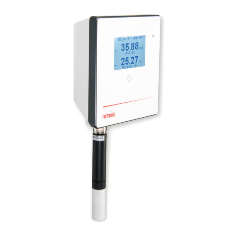
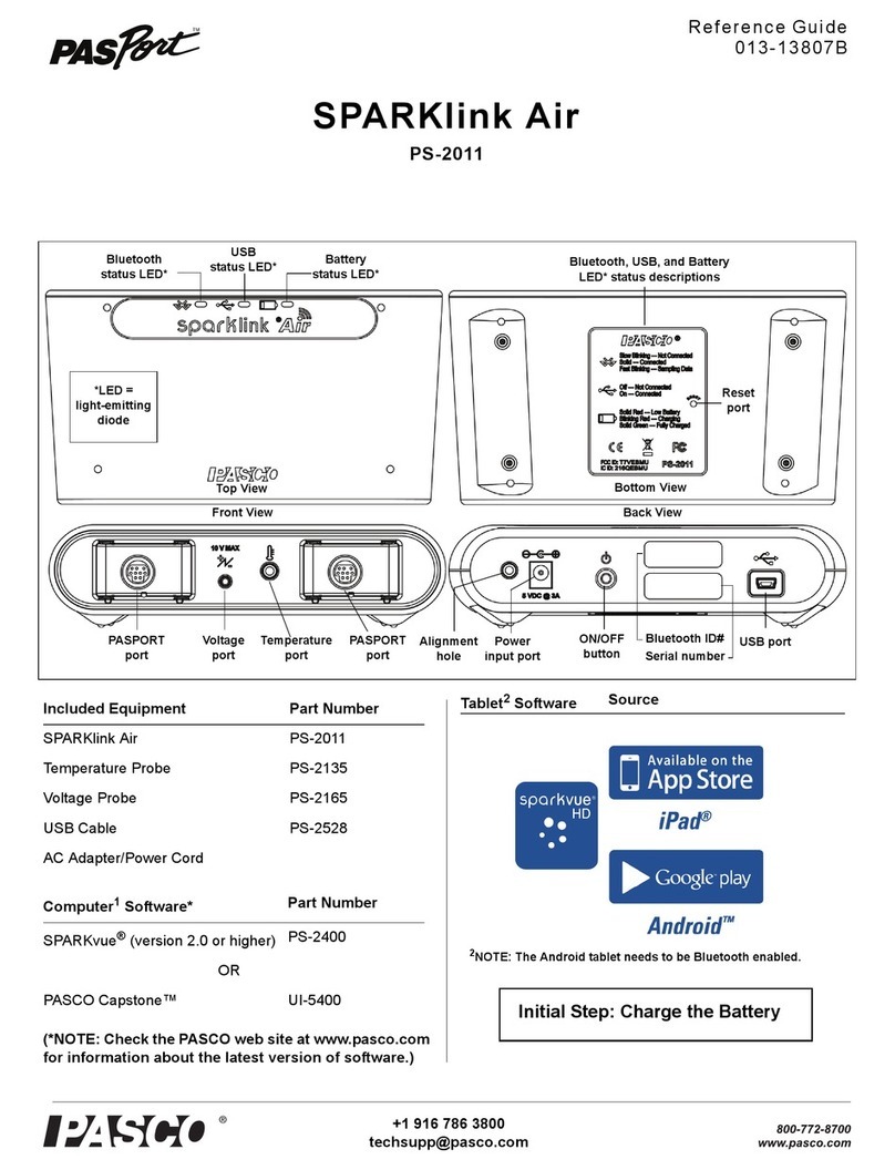
Crystal nVision Reference Recorder User manual

C R Y S T A L
engineering corporation
Operation Manual
Reference
Recorder
Lab Reference

Contents
Introduction.1
Quick.Start.Instructions. 2
Numerical.Display.Overview. 4
Numerical.Upper.and.Lower.Module.screens. 4
Numerical.Dual.Mode.Screen.(Both.Sensors). 4
Graphical.Display.Overview . 5
Graphical.Upper.and.Lower.Module.screens . 5
Graphical.Dual.Mode.Screen.(Both.Sensors). 5
Navigating.the.Graphical.Display. 5
Operating.Instructions. 6
Home.button.6
Next.button.6
Setup.button.6
Clear Peaks (Resetting Hi and Lo Peaks). . . . . . . . . . . . . . . . . . . . . . . . . . . . . . . . . . . . . . . . . 6
Units .......................................................................6
Settings ....................................................................7
Summary ...................................................................7
Recording ..................................................................8
Navigation.&.Select.buttons. 8
Back.button.8
Record.button.8
Power.button..9
Zero.(PM).9
Backlight.button.......................................................10
Display.Screens:..Numerical.and.Graphical . 10
Numerical.Display.Screens.(Live.and.Live.Recording.Data) . 10
Peaks .....................................................................11
Filter ......................................................................11
Numerical.Display.Screen.(Differential.Mode). 12
Upper, Lower and Tare ......................................................12
Graphical.Screens.(Live.Recording,.or.Last.Recorded.Data). 13
Viewing.Graphical.Screen.Data.in.Detail. 14
Complete Data Run Viewing .................................................14
Viewing Specic Data Points or Times ..........................................14
Zooming in on Specic Data .................................................14
Power.(Battery.and.USB). 14
Low.Battery.Indication.. 14
Extending.Battery.Life. 15
Battery.Replacement . 15
USB.power.indication . 16
Reset.16
Automatic.Shutoff . 16

Pressure.(PM).Module.Instructions. 17
CPF.Pressure.Fitting. 17
Measuring.Vacuum. 17
Water.Density.(Inches.of.Water). 17
Overpressure.Conditions . 17
Current,.Voltage,.and.Switch.Test.(MA20).Module.Instructions. 18
Current.Mode.19
Current Measurement .......................................................19
Current Measurement with HART Resistor . . . . . . . . . . . . . . . . . . . . . . . . . . . . . . . . . . . . . . . 19
Voltage.Mode.20
Switch.Test.Mode. 20
Temperature.(RTD100).Module.Instructions. 20
Temperature.Coefcient.of.Resistance.(TCR). 20
Connecting.your.RTD.to.the.RTD100.Module . 21
Modifying.the.Base.Resistance.(Ro) . 22
Resistance.Temperature.Detectors.(RTDs) . 22
Callendar-Van.Dusen.Equation. 23
System.Measurement.Uncertainties.Possible.with.nVision . 24
2-,.3-,.or.4-Wire.Measurements. 25
Differential.Mode.(Pressure.and.Temperature). 26
Upper,.Lower,.Tare.and.Differential.Reading . 26
Upper and Lower Readings ..................................................26
Tare ......................................................................26
Differential Readings ........................................................26
Measurement Uncertainties for two Pressure (PM) Modules using Tare Function . . . . . . 27
Measurement Uncertainties for two Pressure (PM) Modules without Tare . . . . . . . . . . . . 27
Measurement Uncertainties for two Temperature (RTD100) Modules without Tare . . . . . 28
Measurement Uncertainties for two Temperature (RTD100) Modules with Tare . . . . . . . 28
Module.Installation.Instructions. 28
nVision.Application.Specic.Test.Strategies. . 30
Transmitter.Calibration.(Pressure.versus.Current). 30
HART.Transmitter.Calibration.(Pressure.versus.Current). 31
Transmitter.Calibration.(Pressure.versus.Voltage). 32
Switch.Test.(Pressure.versus.Switch.Closure) . 32
Differential.Pressure.(Pressure.versus.Pressure) . 33
Differential.Temperature.(Temperature.versus.Temperature). 34
Calibration.34
nVision.Reference.Recorder.Product.Specications. 36
Model.Numbering.System . 36
Temperature.(Operating.and.Storage). 36
Humidity.36

IP.Rating.36
Electrical.Connection. 36
Mounting.37
Enclosure.37
nVision.Lab.Reference.Product.Specications. 38
Model.Numbering.System . 38
Temperature.(Operating.and.Storage). 38
Humidity.38
IP.Rating.38
Electrical.Connection. 38
Mounting..38
Enclosure.38
nVision.Serial.Numbers. 40
Serial.Number.Location.................................................40
Serial.Numbering.System. 40
Module.Specications..............................................40
Pressure.Module.(PM).Specications . 40
Accuracy .................................................................40
Accuracy in Differential Pressure Mode: . . . . . . . . . . . . . . . . . . . . . . . . . . . . . . . . . . . . . . . . 41
Logging Interval ............................................................41
Media Compatibility ........................................................41
Connection ................................................................41
User Dened Units ...........................................................42
Pressure Conversions ........................................................42
Accuracies, Ranges and Resolutions ..........................................43
Current,.Voltage.&.Switch.Test.(MA20).Specications. 44
Connection ................................................................44
Terminals ..................................................................44
Logging Interval ............................................................44
Entity Parameters ...........................................................44
Accuracy .................................................................45
Ranges, Resolutions and Units ................................................45
mA Input ..................................................................45
HART mA Input .............................................................45
Accuracy .................................................................45
Ranges, Resolutions and Units ................................................45
Switch Detection ...........................................................45
Temperature.Module.(RTD100).Specications. 46
Accuracy .................................................................46
Ranges, Resolutions and Units ................................................46
Wiring Types and TCRs .......................................................46
Connection ................................................................46
Logging Interval ............................................................46
Entity Parameters ...........................................................46
Power.Module.(4AA).Specication. 47
Power .....................................................................47

Intrinsic.Safety. 48
WARNINGS.48
Certications . 48
ATEX.EC.Declarations.of.Conformity. 49
PED.EC.Declarations.of.Conformity. 50
EMC.EC.Declarations.of.Conformity.-.nVision.Reference.Recorder. 51
Software.52
CrystalControl.Conguration.Software. 52
Accessories./.Replacement.Parts. 52
Soft.Carrying.Case (included) ...............................................52
Protective.Boot.(included) ..................................................52
USB.A.to.mini.USB.B.Cable.(included) ........................................52
Test.Lead.Kit.(included in MA20) .............................................52
RTD.Connection.Kit.(included in RTD100) ......................................52
Rack.Mount.Kit.(for nVision Lab Reference only) . . . . . . . . . . . . . . . . . . . . . . . . . . . . . . . 52
ATEX.Safety.Instructions . 53
ČESKY.(Czech) ............................................................53
DEUTSCH.(German) .........................................................53
ENGLISH.(English) ..........................................................54
ESPAÑOL.(Spanish) .........................................................54
FRANÇAIS (French) .........................................................55
ITALIANO (Italian) ..........................................................55
NEDERLANDS.(Dutch) .......................................................56
POLSKI (Polish) .............................................................56
SUOMEN.KIELI (Finnish) ......................................................57
Troubleshooting. 57
Noisy.or.unstable.reading.when.used.with.uids. 57
Non-repeatability.of.pressure.measurements. 58
Slow.return.to.zero.and/or.non-repeatability.of.pressure.measurements . 58
Error.1.displayed. 58
Error.2.displayed . 58
Error.5.or.Error.6.displayed . 58
Error.7.displayed . 58
Trademarks.59
Service.and.Support. 59
How.to.Contact.Us:. 59
Warranty.60


nVision Operation Manual • Page 1
Introduction
Thank you for choosing the nVision Reference Pressure Recorder from Crystal Engineering Corpo-
ration. Your nVision is a combination of leading edge technology and rugged industrial design.
Accuracy is up to 0.025 percent of reading - so any nVision can typically replace several gauges
or calibrators you may have been using. The nVision is fully temperature compensated - so there
is no change in accuracy throughout the entire operating temperature range!
The nVision features two identical bays allowing conguration of the reference recorder to meet
your requirements. All modules are eld-replaceable allowing you the exibility to react to
changing needs and module calibration requirements.
The nVision’s case is made from a rugged injection molded polymer utilizing a gasket to seal the
enclosure against dust and water intrusion. Even the mini USB B connector is fully sealed (with
or without the protective boot cover). Circuitry is mounted in a shock-absorbing elastomeric
system and the batteries are easily accessible by removing four captive screws.
Other features include:
• Log and display 500,000 points at up to 10 readings
per second on up to two modules simultaneously
• Interactive real-time graphing of measurements
• ATEX / IECEx Scheme intrinsically safe
(nVision Reference Recorder only)
• IP67 rated enclosure —1 meter immersion for 30
minutes (nVision Reference Recorder only)
• Uses Crystal’s new CPF ttings and hose system
(leak-free and nger-tight to 10 000 PSI (700 bar))
We hope your nVision meets your expectations, and we’re
interested in any comments or suggestions you may have.
Many features in this and our other products are a direct
result of your comments!
Crystal Engineering is the company that designs, man-
ufactures, markets and services the nVision reference
recorder , XP2i series pressure gauges, 30 series pres-
sure calibrators, MultiCal multimeter pressure adapters
and a variety of industry specic pressure measuring
equipment. Crystal Engineering pioneered features like
full temperature compensation and “of reading” rated
gauges and calibrators. Pressure measuring equipment
is the only thing we do and that’s why we say:
PRESSURE is Our BUSINESS™
Your nVision can also be customized
to meet your specic test needs
through the use of CrystalControl™
software. Your personal computer
can disable, enable or modify a
variety of features of your nVision.
Look for the
logo for user programmable
features, like:
• User dened pressure units, and/
or disable unused pressure units
• Password protection to prevent
unauthorized changes to gauge
settings and/or product keypad
access
• Expand or decrease allowable
Zero range
• Set the gauge to a dierent
density of water factor
(4°C, 60°F or 68°F)
• Store custom ID or tag numbers
in non-volatile memory
• Adjust calibration values

Page 2 • Crystal Engineering Corporation
Quick.Start.Instructions
nVision Chassis Overview
Home button:
Brings you back to the default screen
(lower module numerical display)
Next button:
Progress through the display screens
Backlight button:
Turn on/o display backlight
(Adjust Backlight Shuto)
Zero button:
Press to zero Pressure Module reading (- - - - -)
Hold for 3 seconds to clear any zero value (- - -)
(Adjust Zero Limit)
Power Icon Key - nVision Lab Reference
Icon
Description External Power
(AC Adapter) USB Connection*
*USB Connection is for data transfer only
Power Icon Key - nVision Reference Recorder
Icon
Description External Power
(USB)
100% 75% 50% 25% 0%**
Power Remaining
**Replace Batteries or connect to USB Power
Navigation & Select

nVision Operation Manual • Page 3
nVision Reference Recorder shown.
All instructions on this spread are also applicable to
nVision Lab Reference
Upper Module Bay
Back button:
Previous Display Screen
LED Indication alerts:
: Flashes while recording
(Flashes quickly when recording ends)
: Flashes when an overpressure
condition occurs
Record button:
Start/Stop data recording
(Adjust Logging Interval)
Power button:
Turn your nVision on/o
Lower Module Bay
Setup Button:
Locate additional features:
• Clear Peaks
• Units (Adjust Available units)
Settings
• Contrast
• Lock/Unlock Chassis
Summary
• Chassis, Upper, Lower
Recording
• Start/Stop
• Erase All Runs
This icon represents a component that can be
modied with CrystalControl software

Page 4 • Crystal Engineering Corporation
Numerical.Display.Overview
Numerical.Upper.and.Lower.Module.screens
Lower Module Screen (Default)
Dual Module Screen (Both Sensors)
Upper Module Screen
High / Low:
Peak always measured at
10 readings per second
Filter:
20-reading moving
window (xed)
Maximum Working Pressure:
(Pressure Module Only)
Selectable Units (via Setup button)
Vertical Scale:
Applied versus
full-scale pressure
Numerical.Dual.Mode.Screen.(Both.Sensors)
Sensor Reading biased towards applicable module
(Upper Module reads higher on the screen,
Lower Module reads lower on the screen)

nVision Operation Manual • Page 5
Graphical.Display.Overview
Graphical.Upper.and.Lower.Module.screens
Lower Module Screen
Dual Module Screen (Both Sensors)
Upper Module Screen
Date and Time Stamping
Date and Time Stamping
Test safely with live readings
annunciated regardless of
cursor location or zoom level
Graphical.Dual.Mode.Screen.(Both.Sensors)
Navigating.the.Graphical.Display
In the graphical modes the nVision navipad enables you to control how you view your data.
Data Scroll Using the & keys allows you to navigate to specic
points along your run, while displaying reading and time information.
Graph Zoom Using the & keys allows you to zoom in and out of
your recorded run to suit your needs.
Graph Zoom
Data
Scroll R
in
out
L

Page 6 • Crystal Engineering Corporation
Operating.Instructions
The nVision reference recorder is designed to be robust and easy to use. The following is further
detail on the functionality of the product that may already be summarized in the Quick Start
Instructions above. The main button features, clock-wise are:
.Home.button
The nVision reference recorder has multiple viewing screens available for your use. If
you ever need to get “home” simply press the home button to get you to a familiar or default
view (lower module numerical screen).
. .Next.button
On the nVision, pressing the next button allows you to scroll through the available
nVision screens. Available views are lower module numerical, upper module numerical, dual
module numerical, lower module graphical, upper module graphical and dual module graphical
depending upon how your nVision is populated.
. .Setup.button
Pressing the setup button brings up a selectable menu of features such as Clear
Peaks, Units, Settings, Summary and Recording. Use the navigation button up/down arrows to
move to the desired feature and use the select or right arrow buttons to move into the desired
function.
.XClear.Peaks.(Resetting.Hi.and.Lo.Peaks)
Peak values (Hi and Lo) can be cleared via the setup menu. Press the setup button; navigate to
Clear Peaks with the up/down arrows and use the select button to pick the desired function.
Dashed lines will then briey appear across the display indicating that both peak values (Hi and
Lo) have been cleared. Clearing the peaks will not aect the zero value of the main display and
will not clear the Filter value. If you need to rezero the gauge, simply press the zero button.
.XUnits
Selecting Units allows you to choose the next available unit of measurement. Use the right/left
arrow keys to change the units on the display and press select to accept the change. See the
module specications for the list of available units for your module.
Units not enabled in CrystalControl will not be available for use on the nVi-
sion. Also note that User Dened Units created in CrystalControl will also be accessible in this
listing if enabled.

nVision Operation Manual • Page 7
.XSettings
Display contrast can be adjusted in the Settings menu item. This allows you to optimize your
nVision viewing experience to your ambient lighting conditions and backlight needs. When
Contrast Adjust is highlighted, use your right/left arrows to adjust and press select to capture
the new setting.
The Screen Lock Password feature will also be found in Settings, if enabled
in CrystalControl. Prevent access to your nVision by protecting your device with a 4-digit keypad
lockout set in CrystalControl. Highlight Lock Chassis and press the select button to lock your
nVision (the icon will appear). To unlock the nVision, simply enter the 4 digit password with
the arrow keys and select. The correct password will allow you back into standard nVision op-
eration. An invalid code will reject your attempt and allow you to enter another password.
In the event you lose the password, you will need to contact the factory for an unlock code,
which will remove the password protection.
.XSummary
Not sure of what modules or settings you have loaded in the nVision? The Summary item al-
lows you to view valuable details or settings in your chassis or module. To view a specic mod-
ule summary you will need to choose Chassis, Upper Module or Lower Module. Items in this
section cannot be edited with the nVision chassis but may be modied in CrystalControl. The
specic information in the Summary screens are:
Chassis Summary: Serial Number, Firmware Version, Date/Time, Automatic Shuto, Backlight
Shuto, Logging Interval, Message Store, and module model and serial numbers.
Module : Model, Serial Number, Firmware Version, Calibration Date, Calibration Due, Message
Store, Userspan, Available Units, and module specic information such as Temp. Coecients
(RTD100), Base Resistance (RTD100), Lead Type (RTD100), and Zero Limit (PM)
With the exception of Model, Serial Number, and Firmware Version, all
features can be modied in CrystalControl to optimize your nVision.

Page 8 • Crystal Engineering Corporation
.XRecording
You may Start or Stop a run from the Recording menu item.
CAUTION: Never remove power (either battery or USB power) when Recording.
Additionally you may Erase All Runs in order to eectively manage the 500,000 data point
memory capacity of the nVision. When this command is selected, the nVision will erase the full
on-board memory in less than 2 minutes.
CAUTION: Never remove power (either battery or USB power) during the erasing process.
In order to permanently archive your data, it is recommended to save any
data les via the Export Data le feature in CrystalControl.
.Navigation.&.Select.buttons
Whenever you need to navigate, the nVision utilizes up/down and left/right
arrow navigation buttons. Any time you need to select an object, press the
center select button.
. .Back.button
Pressing the back button allows you to go backward through the available screens
(opposite of next button).
. .Record.button.(. .)
Recording a data run is simple with the nVision. To start (LEDs solid) or stop (LEDs
ash) a recording run from any screen simply press the record button for one second. Record-
ing logs all the available data, so even if you are viewing the lower module numerical display,
the upper data will be recorded and available for CrystalControl downloading, viewing and
archiving. The recording or Logging interval of your nVision can be viewed in the Chassis Sum-
mary Screen, located in the Setup menu.
The product has the capability to record at rates from 10 readings per sec-
ond to 1 reading per hour as set in CrystalControl. Adjust your recording rate to optimize bat-
tery life and data recording needs to your specic application. Note that the nVision will record
all data related to the units checked as “available” in CrystalControl and listed in the Summary
screens. Units that are not checked as “available”, will not be available for downloading, viewing,
or archiving in CrystalControl.
Your nVision memory has capability to record approximately 500,000 data points if both module
bays are populated. If you have one bay populated, this number doubles.
The Automatic Shuto timer will not shut o your nVision while recording.

nVision Operation Manual • Page 9
Recording Rate (Set in CrystalControl)Elapsed recording time to ll memory
(500,000 data points with two modules)
10 readings per second Approximately 14 hours capacity
1 reading per second Approximately 140 hours capacity
(or approximately 6 days)
1 reading per minute Approximately 8300 hours
(or approximately 375 days* )
*Note: batteries will self drain in this time period.
The nVision can store a maximum of 64 recording runs before data must be erased though the
Erase All Runs command in the Setup menu.
CAUTION: Never remove power (either battery or USB power) when Recording.
. .Power.button.
Power up the nVision product by pressing the power button. The nVision will automat-
ically power down if not used for 20 minutes to conserve battery life (or some other duration set
in CrystalControl).
Adjust your Automatic Shuto time (shut o time in absence of key press)
to optimize battery life to suit your needs. Feature is adjustable from 30 seconds to always on
(until batteries are dead). The timer will not shut o your nVision while recording
When powered by USB, the nVision does not employ any power management strategies. There-
fore, it will not automatically shut o to the settings dened by CrystalControl.
CAUTION: Never remove power when Recording.
. .Zero.(PM)
To zero the nVision you must press the button for at least 1 second. The display will then
briey ash all dashed lines (- - - - -), indicating that it has been re-zeroed. If you attempt to zero
the gauge while more than 20 PSI is applied (or the Zero Limit set with CrystalControl), the com-
mand will be ignored, and “- -HI- -” will be displayed.
You can adjust the Zero Limit at which the Zero button will display “- -HI- -”
in CrystalControl. For instance, you could set the maximum zero to 3000 PSI, if you need to mix
high pressure gases. You can disable the zero button by setting the Zero Limit value to zero.
WARNING:
This gauge can display zero pressure when connected to a source of pressure!
Do not rely on the display indication before disconnecting – it may not be indicating true
pressure. Never disconnect pressure instrumentation without rst relieving system pressure!
To clear the zero value on an nVision, hold the button for 3 seconds until the display changes
from (- - - - -) to (- - -).

Page 10 • Crystal Engineering Corporation
. .Backlight.button.(. .)
Pressing the backlight button instantly illuminates the display for a duration set by
CrystalControl. The default duration is 15 seconds and can be custom set all the way up to never
timing out. Battery life is aected by backlight use.
Adjust Backlight Shuto to optimize your illumination needs against battery
performance.
Display.Screens:..Numerical.and.Graphical
The nVision has several dierent screen views to aid in viewing live and recorded data. You may
view in either numerical or graphical modes, and you may view either of the available module
bays individually or in dual mode. You may use the recording capabilities of the nVision from
any screen view you may choose.
The three main data viewing modes are:
1 Live: These are live, real-time readings that are not being recorded into memory (no Record
icon illuminated).
2 Live Recording: Real-time readings that are being recorded ( ) into the 500,000 data
point memory capacity.
3 Last Recorded: This is previously recorded data available for viewing.
Note that you may view all the previously recorded data in CrystalControl,
but only the last recorded run on the nVision chassis.
Numerical.Display.Screens.(Live.and.Live.Recording.Data)
The nVision numerical screens allow you to view live or live recording data in a traditional way.
Peak Hi and Lo, and Filter values are annunciated, in addition to module specic features such as
maximum allowable working pressure (MAWP) of the module (PM ), vertical pressure scale (PM)
and of course, the unit of measure.
Your default (or Home) screen is the Lower Module
Numerical view. Information in this screen is biased to-
wards the lower module to help you identify the location
of the module in question. To the right is an example of a
3KPSI module (PM) located in the lower bay (powered by
USB power).
The upper module screen will also have its relevant data biased toward the top for identication
purposes. The following is a representative screen from a temperature (RTD100) module located
in the upper bay.
Lower Module Numerical Screen

nVision Operation Manual • Page 11
Upper Module Numerical Screen
If you desire to view both the upper and lower numerical displays simultaneously, the dual view
is also possible (shown with battery capacity at 100%).
Dual Module Numerical Screen
Peak Detection and Filter
On the nVision, you may view the peak high (Hi), peak low (Lo), and lter (Filter) readings on the
numerical displays. Peak high, peak low and lter values are not saved when the gauge shuts
o; they will reset to the current reading when the nVision is turned on or reset.
.XPeaks
Hi and Lo readings are useful for seeing rapidly changing events such as pressure during a relief
valve test, or longer duration events such as measuring pressure and temperature during pipe-
line hydrostatic testing.
Hi . . . . . . . Maximum recorded reading
Lo . . . . . . . Minimum recorded reading
.XFilter
Filter is the average reading of the main display (and not the average of the Hi and Lo).
It updates in a xed, twenty (20) sample moving window and oers a dampened view of
your data.

Page 12 • Crystal Engineering Corporation
Numerical.Display.Screen.(Differential.Mode)
The nVision will automatically display an additional dierential screen if two similar module
types are installed at the same time. An example of this would be two pressure modules (PM)
or two RTD100 modules installed simultaneously. In the case of the pressure modules (PM), this
mode does not require them to be the same full scale range.
WARNING: Two MA20 modules are not allowed to be installed at once as this
conguration may permanently damage your nVision.
The dierential screen is shown in the following
example and will be located on your nVision after
the Dual Module Numerical Screen. The ∆P or ∆T
represents a ltered reading of the upper module –
lower module + tare reading.
.XUpper,.Lower.and.Tare
Your nVision will annunciate the live readings for both the upper and lower sensors for your
easy viewing. Both the Upper and Lower readings in this mode are ltered with a xed, twenty
(20) sample window that oers a dampened view of your data. Additionally it also contains a
Tare function that allows you to equalize the upper and lower sensor readings. To clear the Tare
value in Dierential Mode, hold the button for 3 seconds until the main display readings
change from (- - - - -) to (- - -).
+ Upper . . . Filtered live reading of upper module
– Lower . . . . Filtered live reading of lower module
+ Tare . . . . . Allows ability to equalize lower module to upper by pressing the button
until the display briey ashes all dashed lines (- - - - -). See the Dierential Mode section for
further details on improving your measurement uncertainty while using this function.
You may independently change the units of the Upper/Lower or Tare/∆P or ∆T readings through
the Setup button. The units selected for this view are independent of the units selected for the
other screens such as the Dual or Graphical views. Data viewed in the Graphical screens will
represent the data acquired from either module and not represent the specialized view of the
Dierential Mode.

nVision Operation Manual • Page 13
Graphical.Screens.(Live.Recording,.or.Last.Recorded.Data)
The nVision graphical screens allow you to view live recording or last recorded data utilizing
the advanced viewing capabilities of the nVision display.
Like the numerical screens, the border of the graphical screens wraps around the display with a
bias towards the module under test. The following is an example of a 3KPSI module (PM) located
in the lower bay, with the cursor moved to the center of a 57 second Live Recording run (REC
icon is present).
Lower Module Graphical Screen
The upper module data will also have its border wrapping around the top for identication
purposes. The following is a representative screen from a temperature (RTD100) module located
in the upper bay.
Upper Module Graphical Screen
If you desire to view both the upper and lower graphical displays simultaneously, the dual view
is also possible.
Dual Module Graphical Screen
When viewing data with a dual PM or dual RTD100 module installation, the graphed data will
represent the actual, pre-tare readings and not the ∆P or ∆T reading. As a result, the Tare value
will not be indicated in this view.
Horizontal Time Bar
Date and time of cursor location

Page 14 • Crystal Engineering Corporation
Viewing.Graphical.Screen.Data.in.Detail
(Live.Recording,.or.Last.Recorded.Data)
.XComplete.Data.Run.Viewing
When viewing the nVision graphical display screens the live recording data streams into the
viewing window from the right hand side of the display. Therefore, live recording data will
always appear on the far right hand edge of the display when you are viewing the complete
recording session.
The nVision also comes with a cursor for your use within the display window. When the cursor is
located in the default far right side of the screen, the cursor arrows will report live readings for
the populated modules. You will also notice the lower horizontal time bar reporting the increas-
ing duration of the live recording data. This helps you identify the size of your recorded data
window shown on the nVision.
.XViewing.Specic.Data.Points.or.Times
Moving the cursor from the far right hand side of the display allows you to view specic data
points or time stamps within the displayed run. As you move the cursor with the right/left arrow
keys ( / ) you will notice the time stamp changing in the lower right hand box. This is the time
stamp of the specic data point corresponding to the cursor location and reading. If you are
searching for a specic measurement within your recorded test, use the cursor readings or time
stamp to locate the required information. Return the cursor to the far right location by using the
right arrow key.
To ensure safety, Live readings are always annunciated on the display regardless of cursor loca-
tion or zoom level.
.XZooming.in.on.Specic.Data
You may also zoom in or out on your cursor data view by using the up/down arrow keys
( / ).
When zoomed to any level other than the full data view, small arrows will appear at each end of
the horizontal time bar. This time bar describes the size of the window displayed on the nVision.
During any zooming keystroke a zoom in ( )or zoom out ( ) icon will annunciate in the up-
per left hand of the display.
To return to the full zoom out view (viewing complete run) simply hold the down arrow for 5
seconds or until you are completely zoomed out.
Power.(Battery.and.USB)
Low.Battery.Indication.
The battery icon has the following states:
100% 75% 50% 25% 0% USB Power
This manual suits for next models
1
Table of contents
