Crystal SJ-3560 User manual
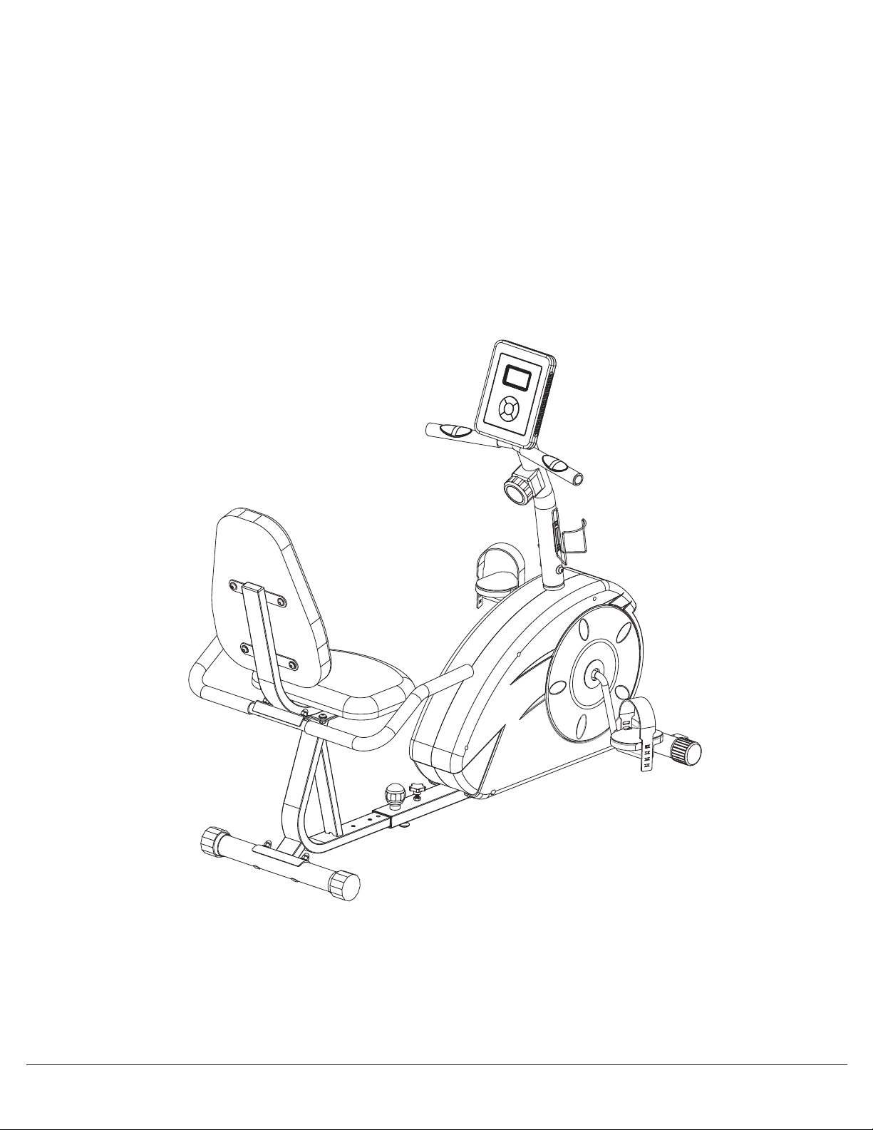
MAGNETIC
RECUMBENT
BIKE
OWNER’S MANUAL
* This item is for consumer use only and it is not meant for commercial use.

Page 1
General Information
Warranty
Body Flex Sports warrants your product for
a period of 1 year for the frame and 90 days
on all parts if the item is used for the intended
purpose, properly maintained and not used
commercially. Any alterations or incorrect
assembly of the product will void this warranty.
Proof of purchase must be presented for any
warranty validation (no exceptions). This
warranty applies to the original purchaser only
and is not transferable.
This warranty does not cover abuse or defects
caused during use, storage or assembly.
During the warranty period, Body Flex Sports
reserves the right to:
a). provide replacement parts to the
purchaser in an effort to repair the item.
b). repair the product returned to our
warehouse (at the purchaser’s cost).
c). replace the product if neither of the two
previously mentioned actions effect repair.
This warranty does not cover normal wear and
tear on upholstery.
Questions
If you have any questions concerning the
assembly of your item or if any parts are
missing, please DO NOT RETURN THE
ITEM TO THE STORE OR CONTACT THE
RETAILER. Our dedicated customer service
staff can help you with any questions you may
have regarding the assembly of this unit and
can also mail you replacement parts.
Customer Support
Customer Support is open 9:00 a.m. to 5:00
p.m. (Pacific Time) Monday through Friday.
Please contact us by any of the following
means.
Safety
Before you undertake any exercise program,
please be sure to consult with your doctor.
Frequent strenuous exercise should be
approved by your doctor and proper use
of your product is essential. Excessive or incorrect
training may result to health injuries. Please read
this manual carefully before commencing the
assembly of your product or starting to exercise.
• Please keep all children away from this item
when in use. Do not allow children to climb or
play on them when they are not in use.
• Supervise teenagers while they use this unit.
• For your own safety, always ensure that there
is at least 3 feet of free space in all directions
around your product while you are exercising.
• Regularly check to see that all nuts, bolts and
fittings are securely tightened. Periodically
check all moving parts for obvious signs of
wear or damage.
• Clean only with a damp cloth, do not use
solvent cleaners. If you are in any doubt, do
not use your product; contact CUSTOMER
SUPPORT.
• Before use, always ensure that your product
is positioned on a solid, flat surface. If
necessary, use a rubber mat underneath to
reduce the possibility of slipping.
• Always wear appropriate clothing and
footwear such as training shoes when
exercising. Do not wear loose clothing that
could become caught in moving parts during
exercise.
• Do not use this unit if it is not functioning
properly or if it is not fully assembled.
• Do not use this unit for commercial purposes.
This unit is for home use only.
Storage and Use
Your product is intended for use in clean
dry conditions. You should avoid storage in
excessively cold or damp places as this may
lead to corrosion and other related problems.
Weight Limit
Your product is suitable for users weighing:
250 pounds or less.
• Before use, you must read and understand all
instructions & warnings stated in this Owner’s
Manual as well as posted on the equipment.
• It is the facility owner’s responsibility to properly
instruct users on the proper operation of the
equipment and to warn them of the potential
hazards.
• If at any time during exercise you feel faint, dizzy
or experience pain, stop and consult your
physician.
Assembling Tools
- Ruler with both metric and English measurements
- 2 x Adjustable Wrenches
- 1 x Philips (”Crosshead”) Screw Driver
•
Any adjustment devices that could interfere with
the user's movement on this unit should not be
left projecting.
SJ-3560
Hangzhou Crystal Sports Equipment Co., Ltd.
Email: [email protected]
Https://hzcrystal.en.alibaba.com/
Http://www.hzcrystal.com/
Tel:+86-0571-69505088
WhatsApp/skype: +8618094780026
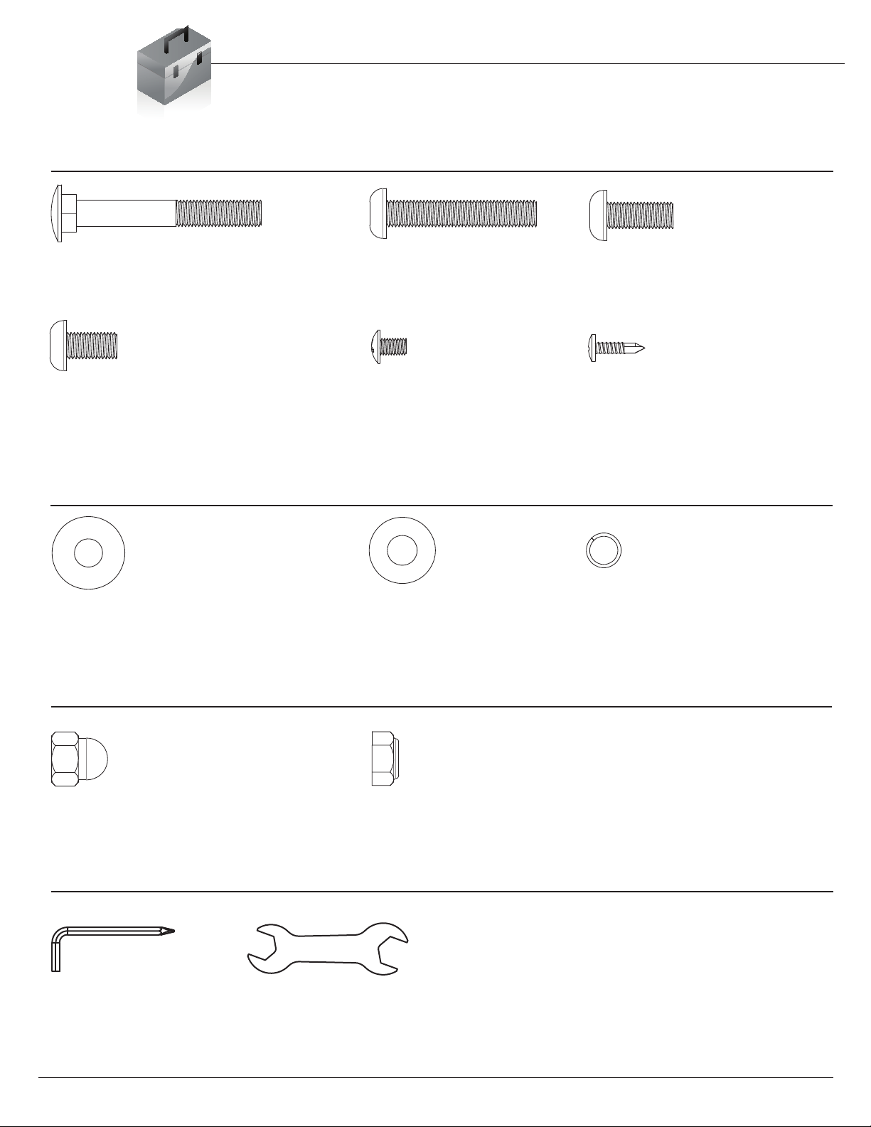
Hardware & Tool List
The following hardware is used to assemble your unit. Please take a moment to familiarize yourself with these
items. Please note, most of these parts are already pre-assembled on your unit. Do not be alarmed if you see
parts on this page that are not included in your hardware packet.
#31. Carriage Bolt (M8x60 mm)
[4 pieces]
#32. Bolt (M8x45 mm)
[2 pieces]
#33. Bolt (M8x20 mm)
[4 pieces]
Pre-assembled (4 pieces)
Washer
Bolt
#43. Arc Washer (M8)
[10 pieces]
#45. Washer (M8)
[18 pieces]
#47. Spring Washer (M8)
[6 pieces]
Nut
#40. Nut (M8)
Tool
#34. Bolt (M8x15 mm)
[12 pieces]
#37. Screw (M5x10 mm)
[4 pieces]
#38. Screw (ST4x15 mm)
[2 pieces]
Pre-assembled Pre-assembled
#41. Nylon Nut (M8)
[4 pieces]
[6 pieces]
Pre-assembled [4 pieces] Pre-assembled [4 pieces]
Tool 1 Tool 2
[1 piece]
[1 piece]
Page 2
SJ-3560

Parts Listing
The following parts list describes all of the parts illustrated on the
exploded diagram on the following page. Please note, most of
these parts are already pre-assembled on your unit.
# Description # Description
01 Main Frame 24 Round End Cap (25 mm)
02 Bottom Frame 25 Front Roller
03 Front Stabilizer 26 Rectangular Cap (53x23 mm)
04 Rear Stabilizer 27 Bottom Frame Sleeve
05 Front Post 28 Spring Loaded Knob (M16x25 mm)
06 Cushion Frame 29 Knob Bolt (M8x20 mm)
07 Rear Handle Bar 30 Knob
08 Backrest Cushion 31 Carriage Bolt (M8x60 mm)
09 Seat Cushion 32 Bolt (M8x45 mm)
10 Monitor 33 Bolt (M8x20 mm)
11 Crank 34 Bolt (M8x15 mm)
12L Left Pedal 35 Hex Bolt (M6x50 mm)
12R Right Pedal 36 Screw (M5x45 mm)
13 Water Bottle Holder 37 Screw (M5x10 mm)
14 Foam Grip for Rear Handle Bar 38 Screw (ST4x15 mm)
15 Foam Grip for Front Handle Bar 39 Screw (ST4x20 mm)
16 Tension Controller 40 Nut (M8)
17 Tension Controller Cable 41 Nylon Nut (M8)
18 Monitor Wire (Lower) 42 Nylon Nut (M6)
19 Monitor Wire (Middle) 43 Arc Washer (M8)
20 Monitor Wire (Upper) 44 Arc Washer (M5)
21 Hand Pulse Sensor 45 Washer (M8)
22 End Cap for Front Stabilizer 46 Washer (M6)
23 End Cap for Rear Stabilizer 47 Spring Washer (M8)
Page 3
SJ-3560
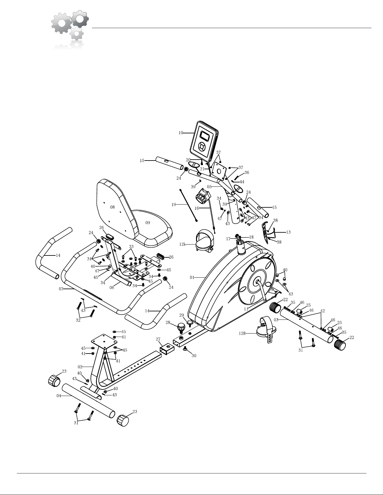
Exploded Diagram
The following diagram is provided to help you familiarize yourself with the parts and
hardware that will be used during the assembly process. Please note that not all of the
parts and hardware you see here will be used while you are assembling the machine
because some of these items are already pre-installed. Please continue to the next
page to begin the assembly process and use this page only as a reference guide for
parts and hardware.
Page 4
SJ-3560
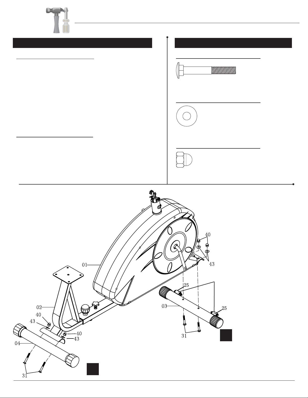
#31. Carriage Bolt (M8x60 mm)
[4 pieces]
Washer
Bolt
#43. Arc Washer (M8)
[4 pieces]
Nut
#40. Nut (M8)
[4 pieces]
A.) Front Stabilizer Assembly
Attach the Front Stabilizer (#03) to the front of Main
Frame (#01) as illustrated below using two Carriage
Bolts (#31), two Arc Washers (#43), and two Nuts
(#40). Please note, the Front Stabilizer (#03) is the
one with transportation wheels attached.
B.) Rear Stabilizer Assembly
Attach the Rear Stabilizer (#04) to the back of Main
Frame (#01) as illustrated below using two Carriage
Bolts (#31), two Arc Washers (#43), and two Nuts
(#40).
A s s e m b l y S t e p 1
Page 5
H a r d w a r e R e q u i r e d
Assembly Instructions
Front Rollers
(After assembly is complete,
see Page 12 for instructions on
“HOW TO MOVE/TRANSPORT THE BIKE
FOR STORAGE”)
A
B
SJ-3560

A s s e m b l y S t e p 2
Page 6
Insert the tip of the Tension
controller (#16) wire into the
Tension Controller Cable (#17)
head at an angle. Tilt the Tension
Controller (#16) wire into the
crevice and then pull upward.
TENSION WIRE ASSEMBLY
Hardware Required
Washer
Bolt
#43. Arc Washer (M8)
[4 pieces]
#47. Spring Washer (M8)
[4 pieces]
#34. Bolt (M8x15 mm)
[4 pieces]
Cable & Front Post Assembly
Remove the pre-assembled parts from Main Frame
(#01) and set them aside nearby: Four Bolts (#34),
four Spring Washers (#47), and four Arc Washers
(#43).
With the help of an assistant, connect Monitor Wire
(Middle) (#19) to Monitor Wire (Lower) (#18) as
show in exploded diagram A, and Tension Controller
(#16) to Tension Controller Cable (#17) as shown in
exploded diagram B.
Then, being careful to tuck the connected wires into
the hollow tubing to avoid pinching/damaging the wires,
slide Front Post (#05) onto the protruding tube of
Main Frame (#01). Secure using a total of four Bolts
(#34), four Spring Washers (#47), and four Arc
Washers (#43) that were set side nearby.
AB
Assembly Instructions
SJ-3560

Assembly Step 3
Page 7
Hardware Required
#33. Bolt (M8x20 mm)
[4 pieces]
Washer
Bolt
#45. Washer (M8)
[8 pieces]
Nut
#41. Nylon Nut (M8)
[4 pieces]
Cushion Frame Assembly
Attach the Cushion Frame (#06) to the Bottom Frame
(#02) as illustrated below by inserting four Bolts (#33)
through four Washers (#45) down into the four holes of
the Bottom Frame (#02). Secure using a total of four
Washers (#45) and four Nylon Nuts (#41).
Assembly Instructions
SJ-3560
Assembly Step 4
Page 8
Hardware Required
#32. Bolt (M8x45 mm)
[2 pieces]
Washer
Bolt
#43. Arc Washer (M8)
[2 pieces]
#45. Washer (M8)
[2 pieces]
#47. Spring Washer (M8)
[2 pieces]
Nut
#40. Nut (M8)
[2 pieces]
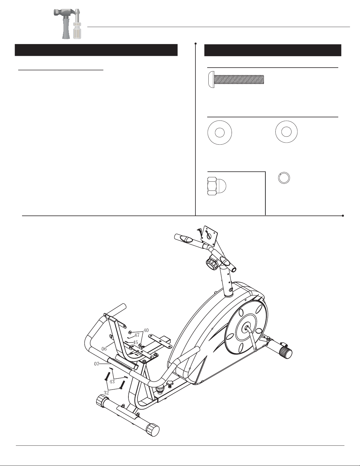
Rear Handle Bar Assembly
Insert the Rear Handle Bar (#07) into the groove
at the back of the Cushion Frame (#06) as
illustrated below and attach using two Bolts (#32),
through two Arc Washers (#43). Secure using
two Washers (#45), two Spring Washers (#47),
followed by two Nuts (#40).
Assembly Instructions
SJ-3560
Assembly Instructions
A s s e m b l y S t e p 5 Hardware Required
Washer
Bolt
#45. Washer (M8)
[8 pieces]
#34. Bolt (M8x15 mm)
[8 pieces]
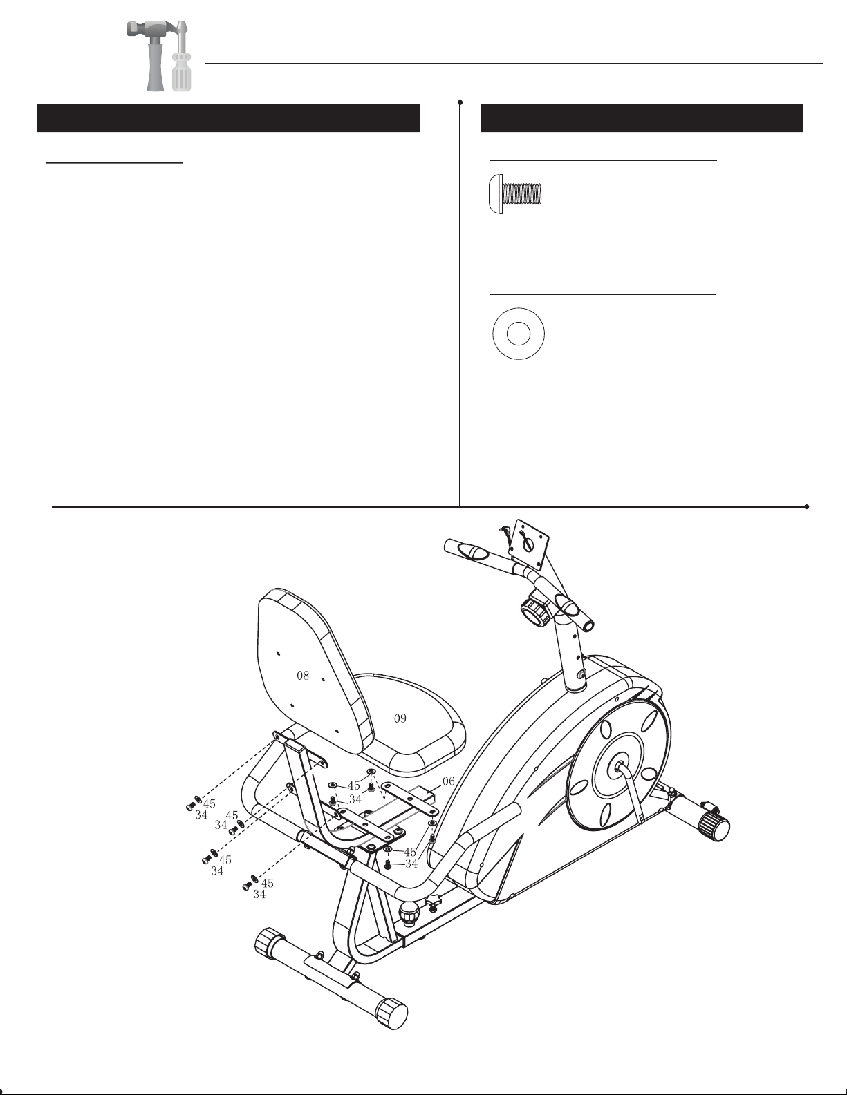
Cushion Assembly
Attach the Backrest Cushion (#08) to the vertical
portion of the Cushion Frame (#06) and secure
using four Bolts (#34) and four Washers (#45).
Then, attach the Seat Cushion (#09) to the
horizontal base of the Cushion Frame (#06) by
inserting upward four Bolts (#34) through four
Washers (#45) to secure.
Page 9
SJ-3560
Assembly Instructions
A s s e m b l y S t e p 6 H a r d w a r e R e q u i r e d
Bolt
#37. Screw (M5x10 mm)
[4 pieces]
#38. Screw (ST4x15 mm)
[2 pieces]
After complete assembly: If the computer
is not picking up your hand pulse signal
(or you are getting inaccurate readings),
Please refer to our “Troubleshooting”
section on Page 15 for other troubleshoot
issues.
HAND PULSE SIGNAL
Troubleshooting
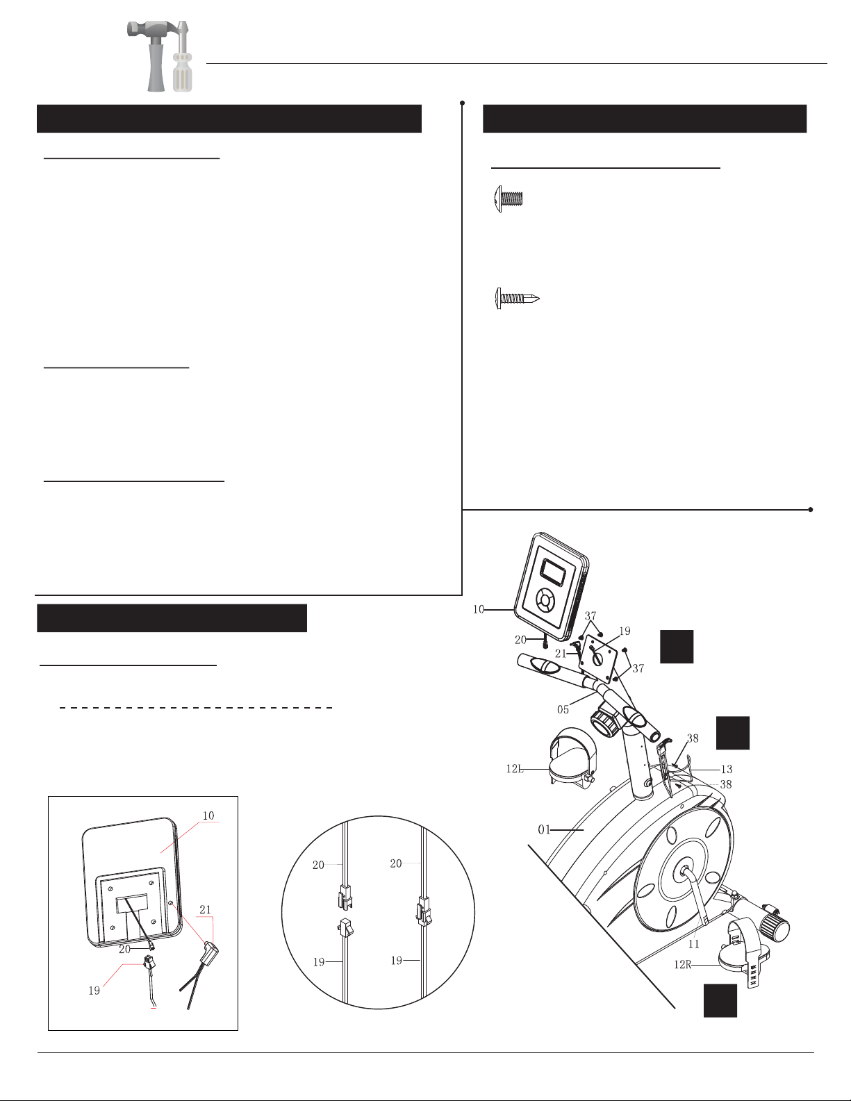
A.) Computer Assembly
Remove the four Screws (#37) that are pre-assembled
on the Monitor (#10) and set them aside nearby.
Attach Monitor Wire (Upper) (#20) to Monitor Wire
(Middle) (#19). Then, attach the Monitor (#10) to the
bracket of Front Post (#05) using four Screws (#37)
that were set aside earlier. Connect Hand Pulse
Sensor (#21) into the power plug hole on the back of
Monitor (#10) as illustrated in exploded diagram.
B.) Pedal Assembly
Screw on the Right Pedal (#12R) to the right Crank
(#11) by turning the Right Pedal (#12R) clockwise.
Repeat on the other side using Left Pedal (#12L) and
turning COUNTER-clockwise.
C.) Water Bottle Holder
Remove the two Screws (#38) that are pre-assembled
on the Front Post(#05) and set them aside nearby.
Attach Water Bottle Holder (#13) to Front Post (#05)
using two Screws(#38) that were set aside earlier.
A
B
C
Page 10
SJ-3560
Assembly Instructions
HOW TO ADJUST THE SEAT
Page 11
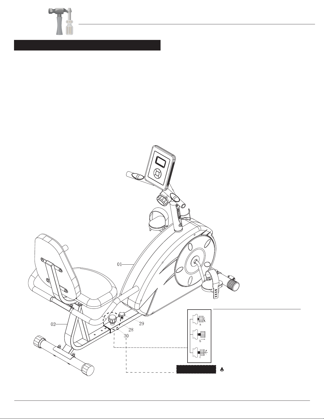
Spring Loaded Knob Operation
Turn knob counter-clockwise three times.
Pull knob outward and adjust bottom frame
simultaneously.
Push knob back inward until it clicks and then
tighten it by turning clockwise.
The Knob (#30) comes pre-assembled on the unit and serves to
enhance its safety and stability. No installation or adjustments are
necessary.
Stability Knob
The Spring Loaded Knob (#28) has a safety feature that allows you to loosen it by turning it counter
-clockwise and then pull upward (to allow for adjusting). Remove the Knob Bolt (#29), adjust the seat distance
and then release the Spring Loaded Knob (#28) back. Making sure it engages through a hole on the
Bottom Frame (#02). Tighten the Spring Loaded Knob (#28) by turning clockwise, and then tighten the
Knob Bolt (#29).
For the user’s safety, always ensure the Spring Loaded Knob (#28) on the Bottom Frame (#02).
(Note: For users shorter in height, slide the Bottom Frame (#02) deeper into the Main Frame (#01), and
farther out for taller users.)
The assembly process is now complete. However, for your own safety, please make sure to read this entire
Owner’s Manual which includes safety instructions and warnings, as well as any safety /warning labels
affixed to the product before use. For your safety, please visually and functionally inspect and test the unit
after assembly is complete.
SJ-3560

Safety & Maintenance
•Make sure all nuts, bolts, and screws are tightened prior to use.
•Be sure that all adjustment locking devices and safety devices are properly engaged prior to use!
•Never over-tighten the above-mentioned devices and parts to avoid damage to the unit.
•Check for loose parts and components and make proper adjustments prior to use.
•Check to see if there are any tears or bends in the welding or metal prior to use. If tears or bends are found,
do NOT use the unit and contact our CUSTOMER SUPPORT.
•Extreme care must be taken to not allow your feet, fingers, hair, clothing, and/or any loose items to be snagged
into any portion of the bike when the unit is in motion. Failure to follow these instructions could result in serious
injury, including the loss of fingers.
•Always wait for the pedals and other moving parts (which can gain great momentum during riding) to come to a
complete stop before dismounting the unit to avoid serious injury.
•Do not use solvent cleaners. If in any doubt, do not use your cleansing product; contact CUSTOMER SUPPORT
MAINTENANCE & CARE
•For any replacement warning labels, please contact our CUSTOMER SUPPORT at (888) 266-6789 or
(909) 598-9876, or mail in a written request to: Body Flex Sports, Inc. 21717 Ferrero Parkway, Walnut, CA 91789.
More detailed information about how to reach our CUSTOMER SUPPORT may be found on Page 1 of the Owner’s
Manual under the “CUSTOMER SUPPORT” section.
•The specific Parts on your unit which may see possible signs of wear after prolonged use are listed as follows
(please check these parts before each use): Tension ControlOHU (#16); Left/Right Pedals (#12L/#12R); Bottom
Frame (#02) and Rear Handle Bar (#07).
•Please review all safety instructions and warnings in this entire Owner’s Manual, as well as any safety/warning
labels affixed to the product before use.
HOW TO (EMERGENCY) STOP
SAFETY & WARNINGS
NOTE: Always wait for the pedals and/or any other moving parts (which can gain great momentum during riding)
to come to a complete stop before dismounting the unit to avoid serious injury.
1. To reduce speed on the bike, you may use the combinations of your feet on the Left/Right Pedals (#12L/R)
and your hands on either set of the front or rear handlebars (Rear Handle Bar (#07) or Foam Grip for Front
Handle Bar (#15)) to gently and safely apply counter-momentum.
2. Wait for the pedals to come to a complete stop.
3. Now you may safely dismount the unit
Page 12
NOTE: To safely move, transport, and/or store the unit, please seek the help of capable assistants (minimum 2
HOW TO MOVE/TRANSPORT THE BIKE FOR STORAGE
people total).The unit has integrated Front Rollers (#25) purposely intended to help ease this process.
1. Position one person on each side at the rear of the bike toward the Seat (one person on the left, and one
on the right).
2. Have each person use both hands to grip the corresponding Foam Grip for Rear Handle Bar (#14) near the
Cushion Frame (#06). (These are the safest areas to avoid injury during this process.)
3. Have both people simultaneously lift the rear end of the unit, leaving the weight and pressure into the front
of the unit and onto the Front Rollers (#25) to move/transport the unit to the desired area.
SJ-3560

Computer Operation
KEY GUIDE
MODE Press this button to perform any of the tasks below:
1. Select “locked” function display (SPEED / DISTANCE / CALORIES / TIME / PULSE)
or SCAN mode.
2. Hold for 3 seconds to reset all of the values to zero.
▲Press any of these buttons to browse through functions.
▼
▲
▲
or
, , ,
Page 13
SJ-3560

Computer Operation
1. Batteries Installation
Please install 2 pieces of AAA 1.5V batteries in the battery case on the back of monitor.
(Whenever batteries are removed, all the functions values will be reset to zero.)
2. Auto On/Off
While the user starts to exercise, the display will show the workout value
automatically. Once the user stops exercising and/or no motion is detected on the unit
for over 8 minutes, the display will turn off automatically.
3. Auto Scan
Press MODE, until the arrow on screen points to “SCAN”. The LCD will rotate display
function values through: -Time - Speed - Distance - Calories . Each value will display and
be held for 4 seconds.
4. Speed
Displays the current workout speed.
5. Distance
Displays the workout session trip distance.
6. Time
Displays the workout session time.
7. Calories
Displays the calories consumed during workout session.
8. Pulse
Displays the current heart rate in beats per minute. To ensure the heart rate readout is
stable, please hold the handgrip sensors with both hands during training. Please refer
to “Troubleshooting” section on Page 14 if you encounter any problems.
*Please be aware that the pulse sensors are not medical devices; the pulse sensors should
not be used or applied for medical reasons.
9. Reset
Press MODE for 3 seconds and all the function values will be reset to zero.
Note:
1. If the computer displays abnormally, please re-install the battery and try again.
2. Battery Spec: AAA (2PCS).
Page 14
SJ-3560

Troubleshooting
If the computer is not picking up your hand pulse signal (or you are getting
inaccurate readings), please adjust the following:
1. Slightly moisten/dampen the palms with water so the sensors can detect a
pulse signal.
2. Do not grip the sensors too tightly. Only moderate pressure need be applied.
Gripping the sensors too tightly restricts and seizes detection of your pulse.
3. Remove any rings or jewelry to prevent interference.
4. Check to ensure all pulse sensor wires are properly connected and are
not damaged.
You may need to refer to installation/assembly directions for the pulse sensor
wires in this manual.
If the computer is not displaying the CALORIES/DISTANCE/TIME/(ETC.) functions
(or you are getting inaccurate readings), please adjust the following:
1. Check to ensure all computer sensor wires are properly connected and are
not damaged.
You may need to refer to installation/assembly directions for the sensor wires
in this manual.
If the computer display is blank & not displaying any data (or does not appear to
power on), please adjust the following:
1. Check to ensure all sensor wires are all properly connected and are
not damaged.
2. Check to ensure the AC Adapter* or Batteries* are properly plugged in or
fully charged.
Troubleshoot Area
HAND PULSE SIGNAL
CALORIES/DISTANCE/
TIME/(ETC.)
COMPUTER Display
(AFTER COMPLETE ASSEMBLY)
Solution
*Please check your product manual to determine if your model uses either
1. an AC Adapter, or 2. Batteries to power your unit.
For your safety, please do not discard this Troubleshooting sheet or the Owner’s Manual,
and keep them in a place where you can easily access/refer to them at any time.
If you are still having any troubleshooting issues, please contact our Customer Support
for further assistance.
Page 15
SJ-3560
Before use, you must read and understand all instructions & warning stated in this Owner's Manual as well as
posted on the equipment.
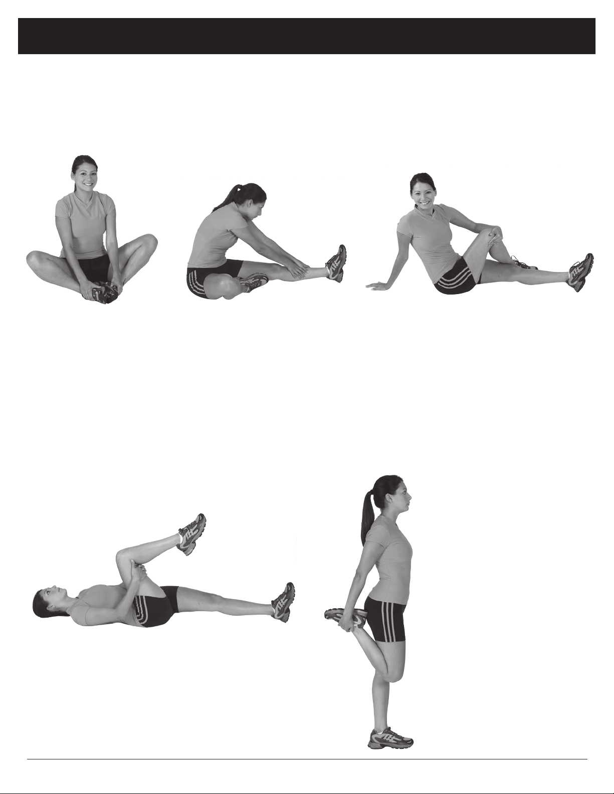
Warm-Up Instructions
Groin Stretch
1. Sit with your knees flexed
and soles of feet together.
2. Hold your ankles and bend
at your hips (keep your
back straight) as you press
your knees toward the
floor with your elbows.
Hamstring Stretch
1. Sit with your left leg extended and bend your right
leg at the knee as you place the sole of your right foot
against the inner thigh of your extended leg.
2. Flex the foot of your extended leg (toes pointed
toward ceiling) and gently bend forward from your
hips; keep your back straight.
3. Reach your hands on your extended leg as far as pos-
sible and then switch legs and repeat.
Trunk Twister
1. Sit with your leg extended and
bend your right knee as you cross
your right leg over your left leg.
Your right foot should be flat on the
floor alongside your left knee.
2. Place your left arm on the outside
of your right leg and pull against
that leg while twisting your trunk
as far as possible to the right. Place
your right hand on the floor behind
your buttocks. Reverse leg posi-
tions and repeat.
Hip Stretch
1. Lie on your back and raise your right leg as you clasp both hands
under the back of the knee. Keep your left leg straight.
2. Gently pull your right leg toward your trunk without raising your
upper body. Switch leg positions and repeat.
The following flexibility exercises are provided to you as a means to prevent injury while you are exercising. A
proper warm-up routine decreases the chance of injuring your muscles while you are exercising. Please take the
time to do these flexibility exercises before and after each time you exercise.
Quadriceps Stretch
1. Stand on your left leg and hold onto
a support with your left hand.
2. Flex your right leg behind you, grasp
your ankle or foot with your right
hand and pull your foot toward your
buttocks. Keep your back straight
and right knee pointed down. Repeat
on the other leg.
Page 16
SJ-3560

Trunk Flexion, Prone
1. Assume the depicted position on your hands and knees. Stretch your hands out in front of you and then slowly start to pull
them back in toward your body as you tuck your chin and arch your back upward.
2. Return to the starting position slowly.
Shoulder Stretch
1. Bring your right hand over
your right shoulder to the
upper back and bring your
left hand under your left
shoulder to the upper back.
2. Try to reach your finger-
tips. If you are not able to
reach your fingertips, use
a towel as an extension of
your hands and gently pull
one hand toward the other.
Reverse arm positions and
repeat.
Calf Stretch
1. Place both hands against
a wall to aid your balance.
Press the ball of your left foot
against the wall and keep the
heel of the same foot rested
on the floor (make sure your
left knee is bent).
2. Slowly start to straighten your
left knee and you will feel
the muscles in your left calf
stretch. Switch leg positions
and repeat.
Warm-Up Instructions
Page 17
SJ-3560
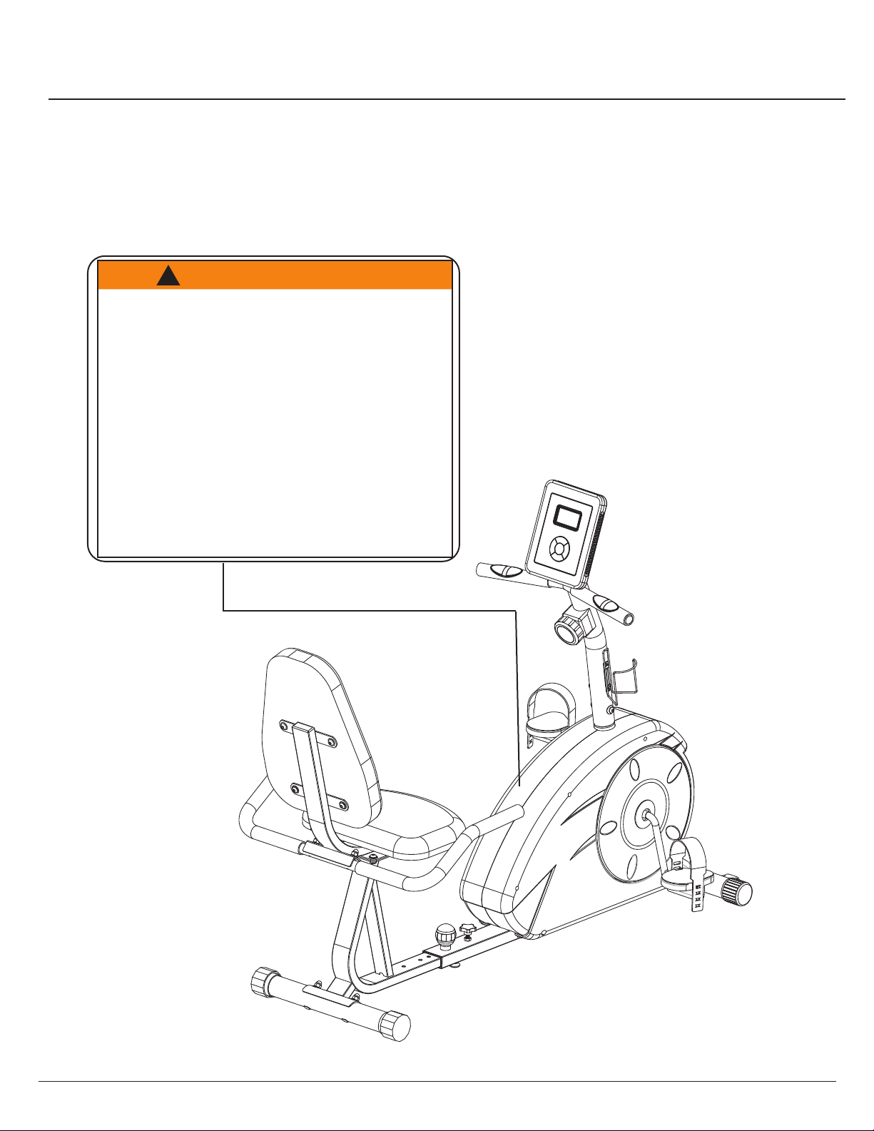
WARNING: SERIOUS INJURIES AND EVEN DEATH CAN OCCUR IF THE PROPER SAFETY PRECAUTIONS ARE NOT FOLLOWED.
The diagram below highlights and reviews many of the important Safety and Warning labels also found
on the unit. Please ensure any user of the unit familiarizes themselves with these Safety and Warning
guidelines before use.
PLEASE KEEP THESE INSTRUCTIONS FOR FUTURE USE & REFERENCE.
DO NOT DISCARD.
Page 18
The use of this exercise equipment involves a RISK OF PHYSICAL INJURY as well as
property damage, which can be minimized by observing the following guidelines:
1. ALWAYS wear comfortable clothing
and shoes with good traction.
2. ALWAYS make sure all nuts and bolts
are secured before use. TIGHTEN
PEDAL HINGE BOLTS EVERY 30
DAYS.
3. STOP EXERCISING if you become
dizzy, nauseous, have irregular
heartbeats or breathing difficulties.
Contact your physician immediately.
4. ALWAYS keep a large mat under the
Equipment to protect the floor or carpet.
5. ALWAYS use your Equipment in a
warm, dry, level well-lit and ventilated
indoor area.
7. ALWAYS keep your Equipment clean
and free of dust, moisture, debris and
loose objects.
8. NEVER use the Equipment if you are
injured or have a physical condition
that impairs your balance. DO NOT
exercise under the influence of
medication or alcohol.
9. NEVER allow small children or pets to
approach the Equipment. It is not a
toy.
10. NEVER use the Equipment if you
exceed its weight limit of 250 lbs.
11. NEVER use the Equipment if it does
not function properly.
6. ALWAYS keep body and clothing free
and clear of all moving parts.
W A R N I N G !
!
SJ-3560
Table of contents


