Crystal RE0412 Installation instructions

ISO 9001:2008/AS9100C:2009
QMS CERTIFIED
DOC-00302 REV B
CRYSTAL GROUP INC.
©2015 BY CRYSTAL GROUP INC. ALL RIGHTS RESERVED.
RE0412 Rugged Embedded Computer Hardware Guide
The most trusted provider for operational, deployable, and high reliability computing applications.

RE0412 Hardware Guide
(RE0412 Hardware Guide) Page 1 of 21

RE0412 Hardware Guide
(RE0412 Hardware Guide) Page 2 of 21
Contents
After selecting a hyperlink, choose ALT and to jump back to original cursor position.
CONTENTS 2
THANK YOU 4
SAFETY 5
ADVISORIES 5
HANDLING PRECAUTIONS 6
BATTERY DISPOSAL 6
A. CONTACT INFORMATION 7
CUSTOMER SERVICE 7
TECHNICAL SUPPORT 7
B. PRODUCT INFORMATION 8
OVERVIEW 8
IDENTIFYING THE SERVER TYPE 8
SPECIFICATIONS 8
C. INSTALLING THE PRODUCT 10
GROUNDING 10
RACK MOUNTING PRECAUTIONS 10
INSTALLING IN AN EQUIPMENT RACK 11
D. OPERATING THE PRODUCT 11
CONNECTING TO THE POWER SOURCE 11
POWERING THE SERVER ON 11
E. MAINTAINING THE PRODUCT 12

RE0412 Hardware Guide
(RE0412 Hardware Guide) Page 3 of 21
DRIVER UPDATES 12
CHASSIS ACCESS 12
EXPANSION/RISER CARD REMOVAL AND
REPLACEMENT 15
HARD DRIVE REMOVAL AND REPLACEMENT 16
MEMORY REMOVAL AND
REPLACEMENT 17
F. TROUBLESHOOTING 18
AVAILABLE WARRANTY 19
CRYSTAL GROUP LIMITED WARRANTY 19
LEGAL INFORMATION 20
COPYRIGHTS AND TRADEMARKS 21
DISCLAIMERS 21
CERTIFICATIONS AND LICENSES 21
12

RE0412 Hardware Guide
(RE0412 Hardware Guide) Page 4 of 21
We Thank You!
From all of us at Crystal Group Inc., THANK YOU for your purchase of the (RE0412). Our
customers are the lifeline that keeps Crystal going. That is why it is extremely important
to us that our customers are 100% satisfied with their product choice.
Crystal products are designed to provide superior performance and reliability in the
harshest environments. Our company is ISO-9001:2008/AS9100C:2009 certified to show
that we are dedicated to providing high quality products to our customers.
We are confident that this server will meet or exceed your expectations for what a
rugged industrial/military computer server should accomplish. If you have any questions
or concerns, please contact us at one of the options listed in the Contact Information
section on page 6.

RE0412 Hardware Guide
(RE0412 Hardware Guide) Page 5 of 21
Safety
Any service should be performed by qualified service personnel. Carefully follow all
advisories and instructions in this guide to avoid causing any bodily injury or damage to
the unit. This product does not contain any user serviceable parts.
ADVISORIES
Three types of advisories are used throughout this guide to emphasize important
information or to warn of potential hazards to the user or equipment. These advisories
each have a specific icon that will stand for one of the following: Note, Warning, or
Caution. An example of each is shown below:
NOTE
A note indicates important information that helps make better use of the equipment.
WARNING
A warning indicates a potential for property damage, personal injury, or death.
CAUTION
Caution indicates potential damage to hardware or loss of data if instructions are not
followed.
RE0412 Hardware Guide
(RE0412 Hardware Guide) Page 6 of 21
HANDLING PRECAUTIONS
This product has components that may be damaged by electrostatic discharge (ESD).
Electrostatic Discharge (ESD)
To protect the equipment from electrostatic discharge, observe the following
precautions when handling or storing the equipment or its components:
1. Always use a grounded wrist strap at the workstation or ground frequently by touching
the metal chassis of the system before handling any components. The chassis must be
connected to an earth ground.
2. Use antistatic padding on all work surfaces.
3. Avoid static-inducing carpet areas.
4. Keep the electronic components in its static shield bag until ready to perform installation
or after removing it from the server.
5. Always handle the memory or expansion cards by the edges.
6. Do not touch the input/output connector pins.
BATTERY DISPOSAL
The following applies to any battery that might be on any board installed in the
equipment:
Danger of explosion if battery is incorrectly replaced.
Replace only with the same or equivalent type recommended by the manufacturer.
Dispose of used batteries according to the m
RE0412 Hardware Guide
(RE0412 Hardware Guide) Page 7 of 21
A Contact Information
Our technical personnel are acutely aware that downtime
experienced by a customer is a mission critical event. They excel at providing timely and
effective responses to any technical issues encountered in the field. Please contact us
with any questions or concerns by using one of the options below:
Customer Service Hours of Operation:
8:00 AM - 5:00 PM Monday through Friday Central Time.
Technical Support Assistance Availability:
7/24/365- 7 days a week; 24 hours a day; 365 days a year.
After hours messaging service is available with a less than 30-minutes response
time.
Within the United States: 800-378-1636
International Number: 1+319-378-1636
Email Address: support@crystalrugged.com
Request a Form Under Tech Support:
http://www.crystalrugged.com
For Up-to-the-minute Crystal Products Information: http://www.crystalrugged.com
RE0412 Hardware Guide
(RE0412 Hardware Guide) Page 8 of 21
B Product Information
OVERVIEW
The Crystal RE0412 is a compact computer in a 3.13 10.76 wide by 8.63
chassis (see section Installing the Product for more information). The (RE0412) consists of
(carbon fiber chassis/enclosure, a power supply, an active motherboard, processor, memory,
and optimal storage).
IDENTIFYING THE SERVER TYPE
Server RE Form, Factor/Approx.
Size, Based on Existing
Key
# of Slots in
Chassis (low
profile only
# of Drives;
(Internal)
RE0412 Rugged
Embedded
04 1 2
SPECIFICATIONS
Mechanical 1U)
Height
Width
Depth
Weight less than 4.25 lbs. (1.93kg) without card
CPU
Intel i3 LGA1155 or i7 RPGA 988B
PROCESSOR, I3-3220, 3.3GHZ, DUAL CORE
W/HT, 3M, 55W, FCLGA1155, INTEL
PROCESSOR, MOBILE CORE I7-3610QE,
2.3GHZ/3.3GHZ TURBO, QUAD CORE, 1600MHZ,
6MB, FCPGA988, 45W, INTEL
Table
1
RE0412 Hardware Guide
(RE0412 Hardware Guide) Page 9 of 21
Memory
Two (2) DDR-3 SDRAM 1066 MHz and
13333 MHz, SO-DIMM, @GB-8GB, 16GB
Capacity
Non-ECC memory
Expansion Slots
PCIe x16 low profile
Drives & I/O (9.5mm)
Cooling
Two (2) high speed fans, thermostatically
controlled
Power Supply
Option 1 (standard) 18-36VDC
AC adapter available
System Board
Intel mini-iTX motherboard, LGA1155 socket,
LAN, 2XUSB 3.0, 2XUSB 2.0, DVI-I, eSATA, HDMI,
Audio
G2 (RPGA 988), Mini-ITX, 3rd Gen Core
17/15/Celleron, 2X 1G Lan, 6X USB-2, 4X USB-3,
2X Sata 3G, DVI, HDMI, VGA, Audio, PCI-E X16,
AAEON, EMB-QM77
Software Compatibility
Accepts Windows 7, Windows 8, or Linux
Military Standards)
For a complete list of Military Standards visit the Crystal Group website at:
http://www.crystalrugged.com
Commercial Standards
Commercial standards are based on the National Electric Code (NFPA70- National Fire
Protection Association). Please visit the following link to learn more about the National Electric
Code standards:
http://www.nfpa.org

RE0412 Hardware Guide
(RE0412 Hardware Guide) Page 10 of 21
C Installing the Product
GROUNDING
DC Version- input installations- use only approved copper connectors.
Reliable Grounding- reliable grounding of rack mounted equipment should be
maintained. Particular attention should be given to supply connections other than direct
connections to the branch circuit (e.g., use of power strips).

RE0412 Hardware Guide
(RE0412 Hardware Guide) Page 11 of 21
D Operating the Product
CONNECTING TO A POWER SOURCE
Please see Section C- Installing the Product on page 9 for more information.
POWERING THE SERVER ON
After securely attaching the power connection, press the Power On/Off switch which will
be located on the front of the chassis configuration. A blue LED will illuminate when
power is applied (see Figure 1, page 12 for location of power switch and more
information about the RE0412 chassis.

RE0412 Hardware Guide
(RE0412 Hardware Guide) Page 12 of 21
E Maintaining the Product
Only qualified service personnel should attempt to open the RE0412 chassis
To protect the equipment from Electrostatic Damage (ESD), follow the proper
precautions at all times when handling the unit and its components. Please see
Electrostatic Discharge section on Page 5.
DRIVER UPDATES
Contact Technical Support at one of the options listed on page 6.
CHASSIS ACCESS
Removing the Cover
1. Make sure the RE0412 is powered off and the unit is disconnected from the power
source.
2. Remove the 4 HW-1501-038 (PAN HEAD 4-40 X 3/8) SS screws connecting the top cover
to the chassis using a Phillips screw driver.
3. Lift the cover to expose the interior of the chassis.
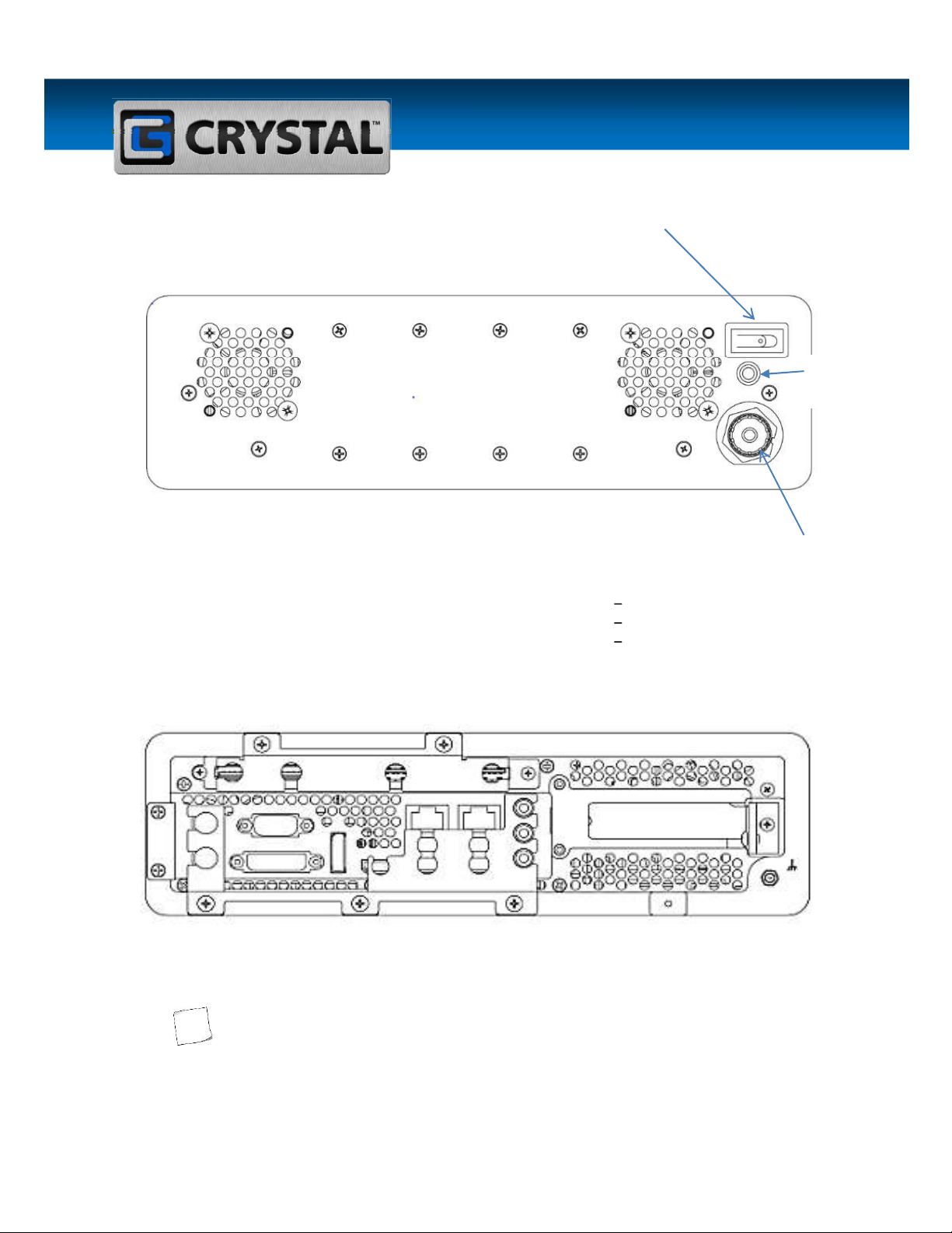
Figure 1. Front View (RE0412)
Note 2
Note 2
Note 2
Note 2
RE0412 Hardware Guide
(RE0412 Hardware Guide) Page 13 of 21
CHASSIS VIEWS:
,
Figure 2. Front View (RE0412)
PWR CONNECTOR
POWER CONNECTOR
CRYSTAL P/N
PINOUT
MINI-CON-X 6382039G-
311 EAC-00712/WHS-00728
PIN 1 DC (-)
PIN 2 DC (+)
PIN 3 GROUND
Figure 3. Rear View (RE0412)
The images above may not depict the product received.
Power Connector
Power LED
Power Switch

RE0412 Hardware Guide
(RE0412 Hardware Guide) Page 14 of 21
INPUT/OUTPUT (I/O) PORTS:
Figure 4. I/O Ports (RE0412)
Mobile
N
U
M
B
E
R
F
U
N
C
T
I
O
N
1
KEYBOARD/MOUSE
CONNECTOR
2
PS/2
MOUSE
3
DVI
4
COM 2
5
DP2
6
HDMI
DPI
-
OPTICAL
7
USB LAN 1
8
USB
9
USB
10
LAN 2
11
USB
12
SATA PORT
13
AUDIO
Table 2
6
5
3
4
2
7
10
13
12
1
9
8
11
RE0412 Hardware Guide
(RE0412 Hardware Guide) Page 15 of 21
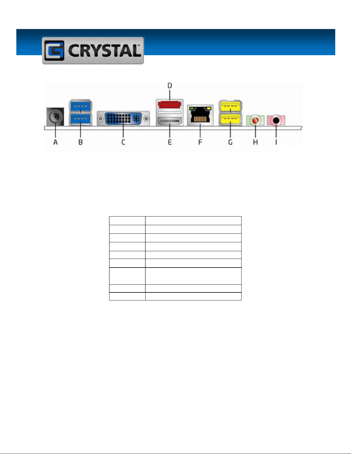
Figure 5. I/O Ports (RE0412)
Desktop
Table 3
A
19 V DC INPUT JACK
B
USB 3.0 PORTS
C
DVI
-
I CONNECTOR
D
eSATA
CONNECTOR
E HDMI CONNECTOR
F
LAN CONNECTOR
G
HIGH
-
CURRENT/FAST
CHARGING USB 2.0 PORTS
H DIGITAL/ANALOG LINE OUT
I MICROPHONE IN
RE0412 Hardware Guide
(RE0412 Hardware Guide) Page 16 of 21
EXPANSION/RISER CARD REMOVAL AND REPLACEMENT
Installing a plug-in expansion card requires an appropriate riser card. Contact a Crystal
Sales Representative or Technical Support if the system does not include a riser card.
Removing and Replacing the Plug-in Expansion/Riser Card
Disconnect power source to prevent injury.
Installing a plug-in expansion/riser card requires opening the (RE0412) cover; inserting
the card into the riser; replacing the card bracket; and disconnecting and reconnecting
the appropriate connectors.
Do not force the card. Forcing the card may result in equipment damage. If it does not
slide into place, check the alignment and try again.
Steps:
1. Turn the unit OFF and disconnect the unit from the power source.
2. Remove the chassis cover (see Removing the Cover on page 16).
3. The card cage is retained by three screws, two from the rear of the unit and one at the
end of the retention bar. Locate and loosen the screws. Carefully slide card cage forward
and lift from chassis.
4. Remove the corresponding expansion slot filler bracket if installed or remove card.
5. Align the expansion card with the riser slot and press the expansion card in firmly. Set the
plug-in cards into the riser card and attach using the pan head screws supplied with the
filler plate.
6. With the expansion card in place within the slot, install the screw and tighten to hold the
card in place.
7. Attach appropriate connectors.
RE0412 Hardware Guide
(RE0412 Hardware Guide) Page 17 of 21
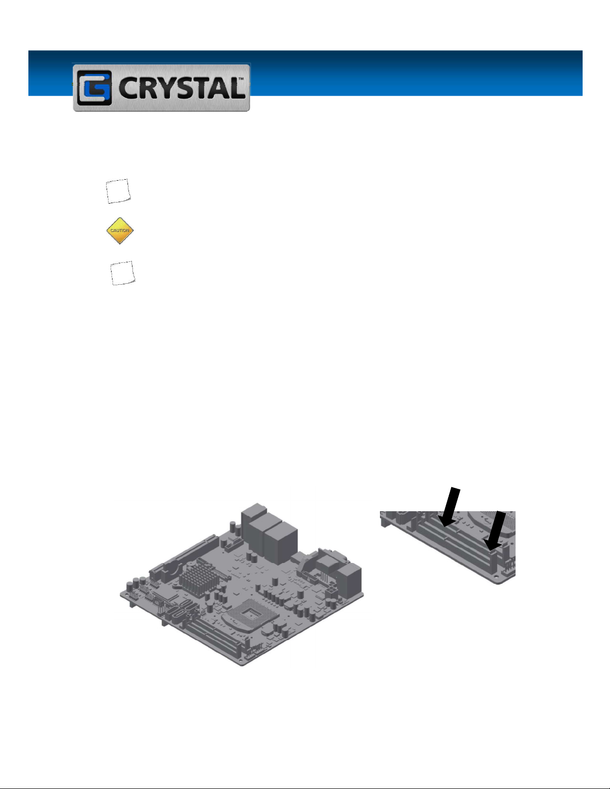
MEMORY REMOVAL AND REPLACEMENT
Removing and Replacing the Memory
Contact Crystal Technical Support before performing a memory upgrade. Use only
Crystal- approved memory for upgrades.
Do not force the DIMM. Forcing the DIMM may result in equipment damage. Check the
alignment and keying before installing.
For population order see the motherboard guide received or contact Technical Support.
Steps:
1. If removal is required, locate the memory card area and open both DIMM release levers
by placing one finger on each lever and pushing outward. See 5 on next page.
2. The DIMM will lightly pop out of the slot. Remove the old DIMM.
3. Check the orientation or key when adding new DIMM.
4. Press the DIMM into its slot evenly on both ends until it clicks into place. The DIMM
release levers will snap into place.
5. The DIMM is properly seated when the release levers have fully engaged.
Figure 6. Installing DIMM

RE0412 Hardware Guide
(RE0412 Hardware Guide) Page 18 of 21
F Troubleshooting
CONTACT TECHNICAL SUPPORT
If any problems arise when using the product, please contact Technical Support at
one of the options listed on page 6. Before calling, please have the following
information available to help expedite assistance:
1. Unit serial number
2. Brief description of the problem
3. Brief explanation of the steps already taken to isolate and resolve the problem
RE0412 Hardware Guide
(RE0412 Hardware Guide) Page 19 of 21
Available Warranty
CRYSTAL GROUP LIMITED WARRANTY
Seller warrants to the Buyer that the products manufactured by it will be free from defects in material and
under this warranty shall be the repair or replacement of any part or parts which prove to be defective under
normal use and service within three (3) years from the date of delivery to the Buyer. To receive the benefits
of this warranty, the Buyer must return said allegedly defective part or pa
Iowa, or other location specified by Seller, within the time period set forth above. A warranty extension
contract is available if purchased, potentially extending the coverage to ten (10) years. Terms and
Conditions of the extension period are dictated in a separate agreement. Customer bears the risk of
loss or damage of equipment in transit from Buyer to Seller. The Buyer shall also pay the costs of shipping
and handling for any service other than Standard Ground
constitute a fulfillment of all liabilities of Seller with respect to this warranty. Buyer shall pay all costs of
procedure, or (b) if Seller reasonably determines that it is unable to resolve the defect by repair or
replacement, to refund the purchase price upon return of the defective item. The warranty period for repaired
or replaced components shall be the remainder of the original warranty period for the repaired or replaced
item. Specifically excluded from this warranty are any products not provided by Seller. Seller will however
horized by
Seller) to the extent that the Buyer agrees to purchase replacement parts or to the extent that an applicable
warranty replacement is available from the OEM of the part. Under no circumstances will this warranty apply
to any software products or preventative maintenance service.
THIS WARRANTY IS EXPRESSLY IN LIEU OF, AND BUYER EXPRESSLY WAIVES, ALL OTHER
WARRANTIES EXPRESSED OR IMPLIED BY STATUTE, USAGE, CUSTOM OF THE TRADE OR
OTHERWISE, INCLUDING THE WARRANTIES OF MERCHANTABILITY OR FITNESS FOR A
IMPLIED WARRANTY OF MERCHANTABILITY OR FITNESS FOR A PARTICULAR PURPOSE IS
HEREBY EXPRESSLY EXCLUDED AND DISCLAIMED. SELLER NEITHER ASSUMES NOR
AUTHORIZES ANY OTHER PERSON TO ASSUME FOR IT, ANY OTHER OBLIGATION OR LIABILITY IN
APPLY TO THIS COMPUTER PRODUCT OR ANY PART THEREOF WHICH HAS BEEN SUBJECT TO
ACCIDENT, NEGLIGENCE, ALTERATION, ABUSE, OR MISUSE. THIS WARRANTY SHALL NOT APPLY
TO ANY PRODUCT FROM WHICH THE ORIGINAL SERIAL TAG HAS BEEN REMOVED. SELLER
MAKES NO WARRANTY WHATSOEVER IN RESPECT TO ACCESSORIES OR PARTS NOT SUPPLIED
BY SELLER. BUYER AGREES THAT SELLER SHALL NOT BE LIABLE FOR ANY PROXIMATE,
CONSEQUENTIAL, PUNITIVE, SPECIAL OR INDIRECT DAMAGES OF ANY AMOUNT DUE TO ANY
CAUSE, INCLUDING, WITHOUT LIMITATION, ANY LOST PROFITS, LOSS OF USE, COSTS OF DELAY,
AINST SELLER
FOR ANY CLAIM OF ANY KIND, INCLUDING BREACH OF WARRANTY, NEGLIGENCE, STRICT
LIABILITY IN TORT, OR PRODUCT LIABILITY, ANY DELAY IN MANUFACTURE OR DELIVERY OF
EQUIPMENT OR PRODUCT, OR FOR ANY FAILURE OF SELLER TO COMPLY WITH THIS
AGREEMENT SHALL BE THE REPAIR OR REPLACEMENT OF THE PRODUCTS AS PROVIDED
HEREIN. (REVISED 1)
Table of contents


