CS Instruments DS 350 User manual
DS 350/330 ICOM DS 350/330 ICOM
DS 350/330 ICOM English, V1.2, 17.12.12 DS 350/330 ICOM English, V1.2, 17.12.12
0970 0060 0970 0060
DS 350/330 industrial communication manual
1
28
CS Instruments (Shenzhen) Co. Ltd.
Room 1506, Hong Qiao Silver City Building, No.933
Zhongshan Road(w), Shanghai, China. 200051
Tel: +86 (0) 21-5111 3860
Fax: +86 (0) 21-5111 3861
Email: sales@csinstrument.com
Website: http://www.csinstrument.com
CS Instruments (Shanghai) branch
Asia Head Quarters
Room 31, Tower B, Cambridge Plaza,188 San Wan Road,
Sheung Shui, N.T. , Hong Kong
Tel: +852 2328 9782
Fax: +852 2542 1310
Email: sales@csinstrument.com
Website: http://www.csinstrument.com
CS Instruments (Asia) Co. Ltd.
Shanghai office
Hong Kong office
Penang Office
303-2-22, Krystal Point, Jalan Sultan Azlan Shah, Bayan Le-
pas, 11900 Penang, Malaysia
Tel: +60-4-643 1522
Fax: +60-4 643 1518
Email: sales@csinstrument.com.my
Website: http://www.csinstrument.com
Kuala Lumpur Office
No.1, Jalan TP3, UEP Subang Jaya Industrial Estate, 47620
Subang Jaya, Selangor, Malaysia
Tel: +603 5122 2082
Fax: +603 5122 5811
Email: sales@csinstrument.com.my
Website: http://www.csinstrument.com
CS Instruments (S.E.A.) Sdn. Bhd.
Malaysia
11A Floor, D3 Building, TCL International E City,
No. 1001 Zhongshanyuan Road, Nanshan District,
Shenzhen 518057, China
Tel: +86 (0)755 - 8619 3164
Fax: +86 (0)755 - 8619 3165
Email: sales@csinstrument.com
Website: http://www.csinstrument.com
(090) 696-6535 or (093) 820-5599
www.gotek.com.vn
Gotek Vietnam Ltd.

DS 350/330 ICOM DS 350/330 ICOM
DS 350/330 ICOM English, V1.2, 17.12.12 DS 350/330 ICOM English, V1.2, 17.12.12
0970 0060 0970 0060
2 27
Order information
Order no. Description
For Field bus connection include one of these options in DS 350/330
A1631 2 inputs for CS flow / dew points sensors + RS-485
A1632 2 inputs for CS flow / dew points sensors + Ethernet
Software
0554 7010 Software CSM-S + DS Configuration software, including USB cable
0599 2020 CS-Monitor CSM-M Basic package up to 5 DS 3xx
0599 2021 CS-Monitor CSM-M Basic package up to 10 DS 3xx
0599 2022 CS-Monitor CSM-M Basic package up to 20 DS 3xx
0599 2023 CS-Monitor CSM-M Basic package up to 30 DS 3xx
0599 7010 CSM-S Software for data analyzes
0598 7010 Upgrade CSM-S
0598 2020 Upgrade CSM-M
A1101 Consumption report generator
Other options
0554 0012 CSBus / Profibus gateway
0554 0010 CSBus / Ethernet gateway
0554 0013 MODBUS / Profibus gateway
0553 0120 Ethernet cable, RF 45 connector both sides, 5 m
0554 0011 RS-485 Repeater
0554 0006 Power supply100-240 VAC input24 VDC, 2 A output, mounted on a hat rail
0554 0007 Power supply100-240 VAC input24 VDC, 0.4 A output, wall mountable casing
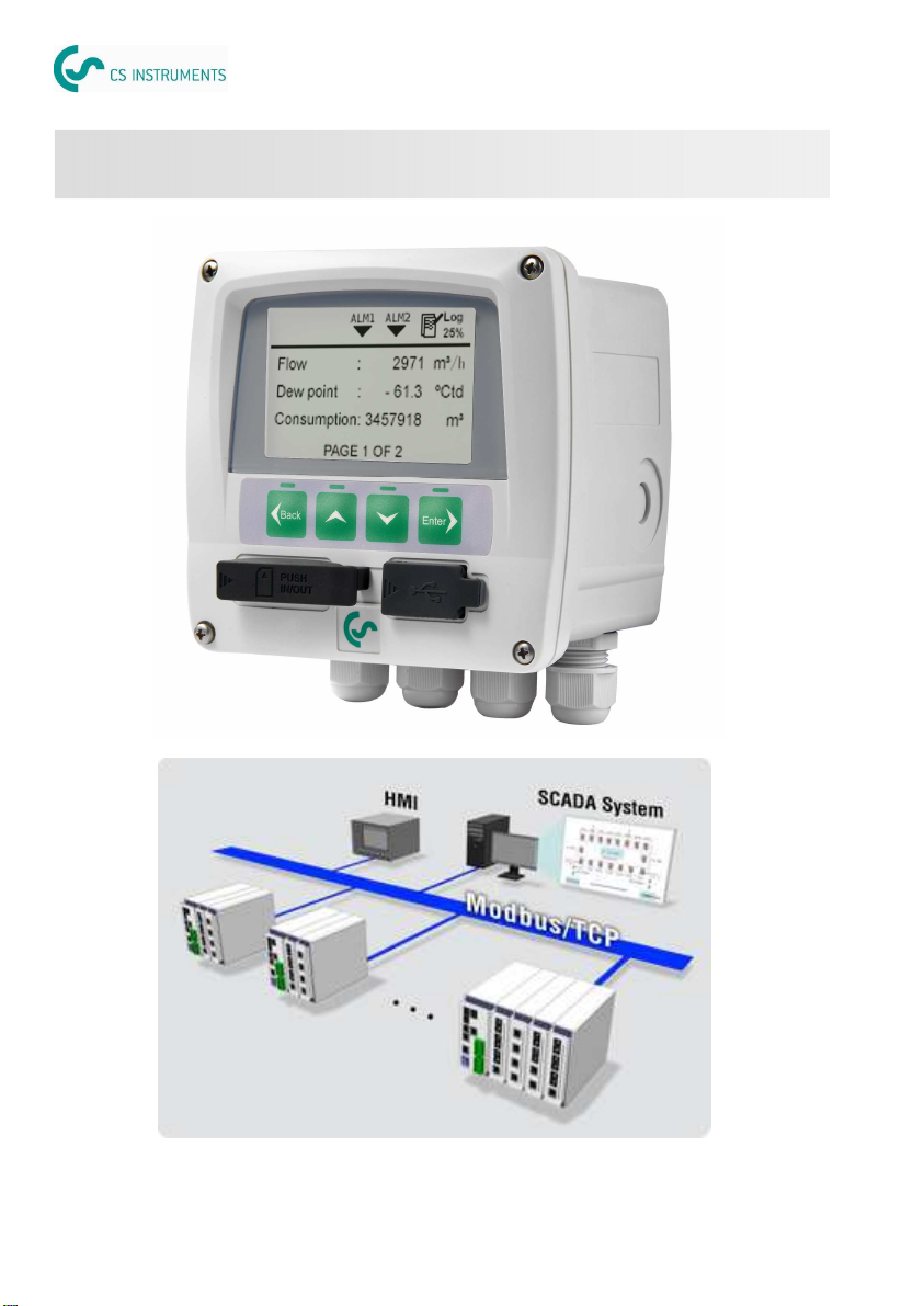
1. Integration of DS 350/330 into an existing Factory Automation System
For this application there are several communication links available which are described briefly
below. All of them in common is the limited functionality to only retrieve measurement data, how-
ever this is sufficient in most applications.
1.1 RS-485 with Modbus/RTU
Modbus is a popular industry bus which can be used to connect several DS 350/330 to a Modbus-
Master which could be a PLC or a SCADA system or a DS 350/330 Master.
DS 350/330 offer various industrial communication options. This manual will describe the differ-
ences of the installation / configuration and supports the user with the installation.
CS offers basically 2 application solutions:
DS 350/330 industrial communication manual
(090) 696-6535 or (093) 820-5599
www.gotek.com.vn
Gotek Vietnam Ltd.
DS 350/330 ICOM DS 350/330 ICOM
DS 350/330 ICOM English, V1.2, 17.12.12 DS 350/330 ICOM English, V1.2, 17.12.12
0970 0060 0970 0060 3
26
8.5 APPENDIX E – Float definition
32-bit floating-point format
The DS 350/330 Modbus module IEEE ‘Little-Endian’ representation for addresses and data
items. This means that when a numerical quantity larger than a single byte is transmitted, the
Least significant byte is sent first.
The data type float is represented by the 32-bit floating-point format. The representation of a 32-
bit floating-point number as an integer is:
bit 31 30 23 22 0
S Exponent Mantissa
The value of the number is:
(-1)
S
* 2
(Exponent-127)
* Mantissa
Read 1
st
display value (Holding register address 0, 2 register)
Request: 0x01, 0x03, 0x00, 0x00, 0x00, 0x02, 0xC4, 0x0B
Response: 0x01, 0x03, 0x04, 0x99, 0x9A, 0x42, 0x55, 0x04, 0x1F
Value
(decimal)
IEEE floating point
format
MSB LSB
Register N
Register N + 1
high low high low
100.0 0x42C80000 0x00 0x00 0x42 0xC8
123.4 0x42F6CCCD 0xCC 0xCD 0x42 0xF6
2.0 0x40000000 0x00 0x00 0x00 0x40
-1.0 0xBF800000 0x00 0x00 0xBF 0x80
-80.0 0xC2A00000 0x00 0x00 0xC2 0xA0 1.3 RS-485 with Gateway to Profibus
To connect DS 350/330 to a Profibus-master CS offers a gateway from CSBus to Profibus. De-
pending on the number of sensors connected to DS 350/330, between 4 to 10 DS 350/330 can be
routed to the Profibus. Profibus provides functionality to retrieve measurement values.
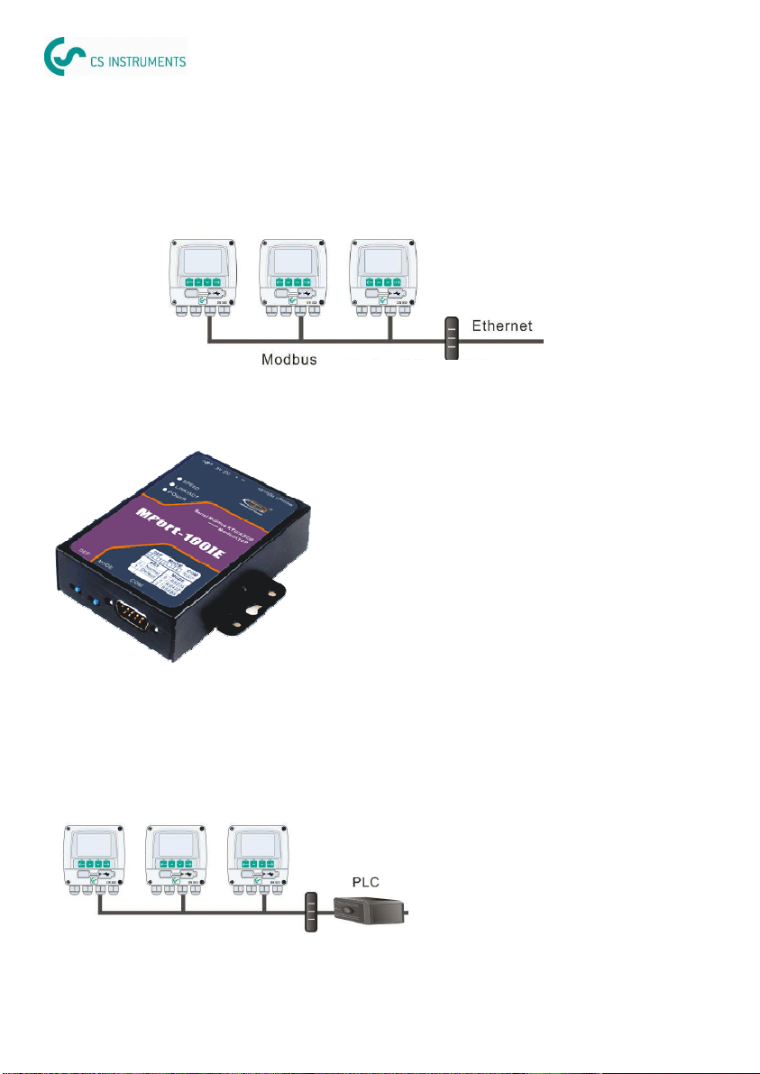
1.2 RS-485 with Modbus / Ethernet Gateway
In areas where Ethernet is not accessible RS-485 can be used to wire the instruments to an ac-
cess point for Ethernet. Through the Modbus / RTU-Modbus / TCP gateway the link to Ethernet is
established. The gateway can handle up to 30 x DS 350/330. Please ensure that Modbus protocol
is selected on DS 350/330 menu.
Attention: This gateway works only in a connection to a Modbus/TCP Master. (see alternative
under 1.4 for Modbus over TCP).
DS 350/330 DS 350/330 DS 350/330
Modbus/RTU --
Modbus/TCP gateway
RS-485/ CSBus
CSBus-Profibus gateway
Modbus/RTU — Modbus/TCP gateway
(0554 0013)
The CSBus - Profibus gateway
(0554 0012) makes a link between
RS-485 slaves running the CSBus
protocol and a Profibus network on
RS-485.
Please contact our customer service
for detailed information.
(090) 696-6535 or (093) 820-5599
www.gotek.com.vn
Gotek Vietnam Ltd.
DS 350/330 ICOM DS 350/330 ICOM
DS 350/330 ICOM English, V1.2, 17.12.12 DS 350/330 ICOM English, V1.2, 17.12.12
0970 0060 0970 0060
4 25
The DS 350/330 Modbus module uses the following exception codes, when responding to the
master.
8.3 APPENDIX B – Exception codes
Exception code Exception name
0x01 illegal function
0x02 Illegal data address
0x03 Illegal data value
0x04 Slave device failure
0x05 Acknowledge
0x06 Slave device busy
For this application CS provides complete solutions, including software for data recording and
analyzes. It offers full functionality to the user and is not limited to retrieving measurement values
only. If measurement values still need to be feed into a SCADA system or a Factory Automation
System, there still the option to use the analogue signals for that purpose (4-20 mA, pulse).
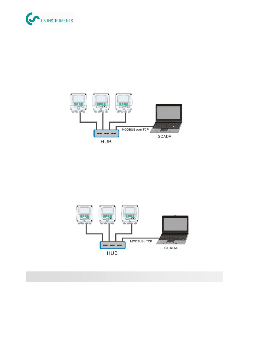
1.4 Modbus/RTU over TCP (Ethernet)
DS 350/330 is available with a Ethernet port. By selecting the Modbus over TCP protocol from the
DS 350/330 menu, the communication with a Modbus master can be established. This is a popu-
lar way to connect to a Modbus Master through Ethernet. Process visualization systems are using
so called OPC servers to establish the link to Modbus.
2. Standalone / Complete solution
1.5 Modbus/TCP (Ethernet)
By selecting the Modbus/TCP protocol from the DS 350/330 menu, the communication with a
Modbus master can be established directly through Ethernet. Attention: when using this option,
communication with the software CSM-S or CSM-M is not possible anymore.
(090) 696-6535 or (093) 820-5599
www.gotek.com.vn
Gotek Vietnam Ltd.

DS 350/330 ICOM DS 350/330 ICOM
DS 350/330 ICOM English, V1.2, 17.12.12 DS 350/330 ICOM English, V1.2, 17.12.12
0970 0060 0970 0060 5
High-Order Byte Table
/* Table of CRC values for high–order byte */
static unsigned char auchCRCHi[] = {
0x00, 0xC1, 0x81, 0x40, 0x01, 0xC0, 0x80, 0x41, 0x01, 0xC0, 0x80, 0x41, 0x00, 0xC1, 0x81,
0x40, 0x01, 0xC0, 0x80, 0x41, 0x00, 0xC1, 0x81, 0x40, 0x00, 0xC1, 0x81, 0x40, 0x01, 0xC0,
0x80, 0x41, 0x01, 0xC0, 0x80, 0x41, 0x00, 0xC1, 0x81, 0x40, 0x00, 0xC1, 0x81, 0x40, 0x01,
0xC0, 0x80, 0x41, 0x00, 0xC1, 0x81, 0x40, 0x01, 0xC0, 0x80, 0x41, 0x01, 0xC0, 0x80, 0x41,
0x00, 0xC1, 0x81, 0x40, 0x01, 0xC0, 0x80, 0x41, 0x00, 0xC1, 0x81, 0x40, 0x00, 0xC1, 0x81,
0x40, 0x01, 0xC0, 0x80, 0x41, 0x00, 0xC1, 0x81, 0x40, 0x01, 0xC0, 0x80, 0x41, 0x01, 0xC0,
0x80, 0x41, 0x00, 0xC1, 0x81, 0x40, 0x00, 0xC1, 0x81, 0x40, 0x01, 0xC0, 0x80, 0x41, 0x01,
0xC0, 0x80, 0x41, 0x00, 0xC1, 0x81, 0x40, 0x01, 0xC0, 0x80, 0x41, 0x00, 0xC1, 0x81, 0x40,
0x00, 0xC1, 0x81, 0x40, 0x01, 0xC0, 0x80, 0x41, 0x01, 0xC0, 0x80, 0x41, 0x00, 0xC1, 0x81,
0x40, 0x00, 0xC1, 0x81, 0x40, 0x01, 0xC0, 0x80, 0x41, 0x00, 0xC1, 0x81, 0x40, 0x01, 0xC0,
0x80, 0x41, 0x01, 0xC0, 0x80, 0x41, 0x00, 0xC1, 0x81, 0x40, 0x00, 0xC1, 0x81, 0x40, 0x01,
0xC0, 0x80, 0x41, 0x01, 0xC0, 0x80, 0x41, 0x00, 0xC1, 0x81, 0x40, 0x01, 0xC0, 0x80, 0x41,
0x00, 0xC1, 0x81, 0x40, 0x00, 0xC1, 0x81, 0x40, 0x01, 0xC0, 0x80, 0x41, 0x00, 0xC1, 0x81,
0x40, 0x01, 0xC0, 0x80, 0x41, 0x01, 0xC0, 0x80, 0x41, 0x00, 0xC1, 0x81, 0x40, 0x01, 0xC0,
0x80, 0x41, 0x00, 0xC1, 0x81, 0x40, 0x00, 0xC1, 0x81, 0x40, 0x01, 0xC0, 0x80, 0x41, 0x01,
0xC0, 0x80, 0x41, 0x00, 0xC1, 0x81, 0x40, 0x00, 0xC1, 0x81, 0x40, 0x01, 0xC0, 0x80, 0x41,
0x00, 0xC1, 0x81, 0x40, 0x01, 0xC0, 0x80, 0x41, 0x01, 0xC0, 0x80, 0x41, 0x00, 0xC1,
0x81,0x40
} ;
Low-Order Byte Table
/* Table of CRC values for low–order byte */
static char auchCRCLo[] = {
0x00, 0xC0, 0xC1, 0x01, 0xC3, 0x03, 0x02, 0xC2, 0xC6, 0x06, 0x07, 0xC7, 0x05, 0xC5, 0xC4,
0x04, 0xCC, 0x0C, 0x0D, 0xCD, 0x0F, 0xCF, 0xCE, 0x0E, 0x0A, 0xCA, 0xCB, 0x0B, 0xC9, 0x09,
0x08, 0xC8, 0xD8, 0x18, 0x19, 0xD9, 0x1B, 0xDB, 0xDA, 0x1A, 0x1E, 0xDE, 0xDF, 0x1F, 0xDD,
0x1D, 0x1C, 0xDC, 0x14, 0xD4, 0xD5, 0x15, 0xD7, 0x17, 0x16, 0xD6, 0xD2, 0x12, 0x13, 0xD3,
0x11, 0xD1, 0xD0, 0x10, 0xF0, 0x30, 0x31, 0xF1, 0x33, 0xF3, 0xF2, 0x32, 0x36, 0xF6, 0xF7,
0x37, 0xF5, 0x35, 0x34, 0xF4, 0x3C, 0xFC, 0xFD, 0x3D, 0xFF, 0x3F, 0x3E, 0xFE, 0xFA, 0x3A,
0x3B, 0xFB, 0x39, 0xF9, 0xF8, 0x38, 0x28, 0xE8, 0xE9, 0x29, 0xEB, 0x2B, 0x2A, 0xEA, 0xEE,
0x2E, 0x2F, 0xEF, 0x2D, 0xED, 0xEC, 0x2C, 0xE4, 0x24, 0x25, 0xE5, 0x27, 0xE7, 0xE6, 0x26,
0x22, 0xE2, 0xE3, 0x23, 0xE1, 0x21, 0x20, 0xE0, 0xA0, 0x60, 0x61, 0xA1, 0x63, 0xA3, 0xA2,
0x62, 0x66, 0xA6, 0xA7, 0x67, 0xA5, 0x65, 0x64, 0xA4, 0x6C, 0xAC, 0xAD, 0x6D, 0xAF, 0x6F,
0x6E, 0xAE, 0xAA, 0x6A, 0x6B, 0xAB, 0x69, 0xA9, 0xA8, 0x68, 0x78, 0xB8, 0xB9, 0x79, 0xBB,
0x7B, 0x7A, 0xBA, 0xBE, 0x7E, 0x7F, 0xBF, 0x7D, 0xBD, 0xBC, 0x7C, 0xB4, 0x74, 0x75, 0xB5,
0x77, 0xB7, 0xB6, 0x76, 0x72, 0xB2, 0xB3, 0x73, 0xB1, 0x71, 0x70, 0xB0, 0x50, 0x90, 0x91,
0x51, 0x93, 0x53, 0x52, 0x92, 0x96, 0x56, 0x57, 0x97, 0x55, 0x95, 0x94, 0x54, 0x9C, 0x5C,
0x5D, 0x9D, 0x5F, 0x9F, 0x9E, 0x5E, 0x5A, 0x9A, 0x9B, 0x5B, 0x99, 0x59, 0x58, 0x98, 0x88,
0x48, 0x49, 0x89, 0x4B, 0x8B, 0x8A, 0x4A, 0x4E, 0x8E, 0x8F, 0x4F, 0x8D, 0x4D, 0x4C, 0x8C,
0x44, 0x84, 0x85, 0x45, 0x87, 0x47, 0x46, 0x86, 0x82, 0x42, 0x43, 0x83, 0x41, 0x81, 0x80,
0x40
};
unsigned short CRC16(unsigned char *puchMsg, unsigned short usDataLen)
{
unsigned char uchCRCHi = 0xFF; /* high byte of CRC initialized */
unsigned char uchCRCLo = 0xFF; /* low byte of CRC initialized */
unsigned uIndex ; /* will index into CRC lookup table */
while(usDataLen—) /* pass through message buffer */
{
uIndex = uchCRCHi ^ *puchMsg++ ; /* calculate the CRC */
uchCRCHi = uchCRCLo ^ auchCRCHi[uIndex] ;
uchCRCLo = auchCRCLo[uIndex] ;
}
return (unsigned short int)((uchCRCHi << 8) | uchCRCLo);
}
24
2.1 Chose the Application Software
CS-Monitor software is designed for this application. It comes with two versions:
CSM-M (CS-Monitor multiple)
CSM-S (CS-Monitor single)
Using CSM-M software
CSM-M is capable to communicate with up to 30 DS 350/330 on a network (Ethernet, RS-485 or
RS-485 / Ethernet gateway). The key features available are:
•
Online measurement values of all instruments and all channels in parallel
•
User can add his own plant schematics as a background picture to the online screen
•
Online recording of selected channels over all instruments
•
Data backup for online recording and recovery after power fail
•
Alarm monitoring and recording of alarm history
•
Start / stop logger inside DS 350
•
Read recorded data from DS 350 data logger
•
Different logger reading options available: read all, read from last stop, etc
•
Report generation and graphical analyzes
Using CSM-S software
CSM-S can communicate through Ethernet and RS-485. It can detect up to 10 DS 350/330 but
only one DS 350/330 can be selected to communicate at a time. The user has to select from a list
of DS 350/330. Through the Ethernet and RS-485 connection the full functionality of CSM-S is
available, for the user it appears as if the device is connected directly to the local USB-Port.
The key features available are:
•
Supporting RS-485 communication besides what CS-Soft supports including USB,
Ethernet and Service kit (connection CS flow / dew point sensors)
•
Up to 10 remote units (DS 350/330) can be detected via RS-485 and Ethernet. How-
ever, it can only communicate with one device at a time
•
Fast logger reading via Ethernet / RS-485 / USB. For Ethernet and RS-485 1000
values per second and for USB 2500 values per second
•
Graphical analyzes and printing
•
Exporting data to MS-Excel files
(090) 696-6535 or (093) 820-5599
www.gotek.com.vn
Gotek Vietnam Ltd.

DS 350/330 ICOM DS 350/330 ICOM
DS 350/330 ICOM English, V1.2, 17.12.12 DS 350/330 ICOM English, V1.2, 17.12.12
0970 0060 0970 0060 23
The Cyclical Redundancy Checking (CRC) field is two bytes, containing a 16-bit binary value.
The CRC value is first generated by the transmitting device, which appends the CRC to the mes-
sage. The device that receives recalculates a CRC during receipt of the message, and compares
the calculated value to the actual value it received in the CRC field. If the two values are not
equal, an error results.
There are many ways of calculating a CRC checksum. To ensure correct calculation, please refer
to [Reference 1] Modbus over serial line, where detailed descriptions and programming examples
are available. Even more information and programming examples in different programming lan-
guages can be found on: www.modbus.org searching for CRC.
Below is a short text description of how the CRC is calculated. This description is then followed
by a C programming example.
8.2.2 CRC Generation
CRC calculation:
10. Load a 16-bit register with FFFF hex (all 1’s). Call this the CRC register.
11. Exclusive OR the first 8-bit byte of the message with the low-order byte of the 16-
bit CRC register, putting the result in the CRC register.
12. Shift the CRC register one bit to the right (toward the LSB), zero-filling the MSB.
Extract and examine the LSB.
13. (If the LSB was 0): Repeat step 3 (another shift). (If the LSB was 1): Exclusive OR
the CRC register with the polynomial value 0xA001 (1010 0000 0000 0001).
14. Repeat steps 3 and 4 until 8 shifts have been performed. When this is done, a
complete 8-bit byte will have been processed.
15. Repeat steps 2 through 5 for the next 8-bit byte of the message. Continue doing
this until all bytes have been processed.
16. The final content of the CRC register is the CRC value.
17. When the CRC is placed into the message, its upper and lower bytes must be
swapped as described below.
Placing the CRC into the Message
When the 16-bit CRC (two 8-bit bytes) is transmitted in the message, the low-order byte will be
transmitted first, followed by the high-order byte.
For example, if the CRC value is 1241 hex (0001 0010 0100 0001):
Addr Func Data count Data Data Data Data CRC Lo CRC Hi
0x41 0x12
RS-485 / CSBus
RS-485 / USB converter
CSM
2.2 Choose the physical connection method
2.2.1 RS-485
RS-485 is commonly used in industrial applications. It can reach up to 1000 m distance with a
shielded 2-wire cable. If further distance is required, a repeater can be installed to reach another
1000 m. Up to 30 DS 350/330 instruments can be connected to the RS-485 network. Please en-
sure that CSBus protocol is selected on DS 350/330 menu and every DS 350/330 has a unique
device address (1 - 255), (see software CSC-350).
Hardware Requirements:
DS350/330 with RS-485 connection (order number: A1631) ready
RS-485 / USB converter (order number: 0554 0331) and driver installed properly
Cabling all the devices and also to the converter
PC with operation system of XP, Vista 32, Vista 64, Windows7 32 or Windows7 64
Software Requirements:
CSM-S
2.2.2 Ethernet (TCP/IP)
DS 350/330 can be connected to an Ethernet switch or router or sometimes called a hub. Please
consider following hardware and software requirements:
CSBus / TCP
CSM Software
6
(090) 696-6535 or (093) 820-5599
www.gotek.com.vn
Gotek Vietnam Ltd.

DS 350/330 ICOM DS 350/330 ICOM
DS 350/330 ICOM English, V1.2, 17.12.12 DS 350/330 ICOM English, V1.2, 17.12.12
0970 0060 0970 0060 7
22
8.2 APPENDIX B – LRC CRC calculation
The Longitudinal Redundancy Checking (LRC) field is one byte, containing an 8–bit binary value.
The LRC value is calculated by the transmitting device, which appends the LRC to the message.
The device that receives recalculates an LRC during receipt of the message, and compares the
calculated value to the actual value it received in the LRC field. If the two values are not equal, an
error results.
The LRC is calculated by adding together successive 8–bit bytes in the message, discarding any
carries, and then two’s complementing the result. The LRC is an 8–bit field, therefore each new
addition of a character that would result in a value higher than
255 decimal simply ‘rolls over’ the field’s value through zero. Because there is no ninth bit, the
carry is discarded automatically.
A procedure for generating an LRC is:
7. Add all bytes in the message, excluding the starting ‘colon’ and ending CRLF. Add
them into an 8–bit field, so that carries will be discarded.
8. Subtract the final field value from FF hex (all 1’s), to produce the ones–complement.
9. Add 1 to produce the twos–complement.
8.2.1 LRC Generation
Placing the LRC into the Message
When the 8–bit LRC (2 ASCII characters) is transmitted in the message, the high–order character
will be transmitted first, followed by the low–order character. For example, if the LRC value is 61
hex (0110 0001):
Example: an example of a C language function performing LRC generation is shown below.
The function takes two arguments:
unsigned char *auchMsg; /* A pointer to the message buffer containing binary data */
/* to be used for generating the LRC, */
unsigned short usDataLen; /* The quantity of bytes in the message buffer. */
LRC Generation Function
static unsigned char LRC(unsigned char *auchMsg, unsigned short usDataLen)
{
unsigned char uchLRC = 0 ; /* LRC char initialized */
while (usDataLen––) /* pass through message buffer */
uchLRC += *auchMsg++ ; /* add buffer byte without carry */
return ((unsigned char)(–((char)uchLRC))) ; /* return twos complement */
}
Colon Addr Func Data
Count Data Data Data Data LRC
Hi LRC
Lo CR
LF
“6”
0x36 “1”
0x31
Hardware Requirements:
DS350/330 with Ethernet connection (order number: A1632) ready
Standard RJ45 Ethernet cable, maximum length 100 meters
DS350/330 connected into a LAN (Local Area Network)
PC with Ethernet connection (XP, Vista 32, Vista 64, Windows7 32 or Windows7 64)
Software Requirements:
CSM-S or CSM-M
2.2.3 RS-485 / Ethernet
In areas where Ethernet is not accessible RS-485 can be used to wire the instruments to an ac-
cess point for Ethernet. Through the RS-485 / Ethernet gateway the link to Ethernet is estab-
lished. The gateway can handle up to 30 DS 350/330. Please ensure that CSBus protocol is se-
lected on DS 350/330 menu and every DS 350/330 has a unique device address (1 - 255).
Hardware Requirements:
DS350/330 with RS-485 connection (A10631) ready
CSBus / Ethernet gateway (0554 0010) ready
Cabling all the devices and also to the gateway
PC with operation system of XP, Vista 32, Vista 64, Windows7 32 or Windows7 64
Software Requirements:
CSM-M
Ethernet
RS-485
(090) 696-6535 or (093) 820-5599
www.gotek.com.vn
Gotek Vietnam Ltd.

DS 350/330 ICOM DS 350/330 ICOM
DS 350/330 ICOM English, V1.2, 17.12.12 DS 350/330 ICOM English, V1.2, 17.12.12
0970 0060 0970 0060 218
Slave address 1 byte
Function code 1 byte
Starting address Hi 1 byte
Starting address Lo 1 byte
No. of registers Hi 1 byte
No. of registers Lo 1 byte
Byte count 1 byte
Data Hi 1 byte
Data Lo 1 byte
: :
Data Hi 1 byte
Data Lo 1 byte
CRC 2 bytes
Slave address 1 byte
Function code 1 byte
Starting address Hi 1 byte
Starting address Lo 1 byte
No. of registers Hi 1 byte
No. of registers Lo 1 byte
CRC 2 bytes
16 (0x10) Write multiple registers
Request Response
17 (0x11) Report slave ID
Slave address 1 byte
Function code 1 byte
CRC 2 bytes
Slave address 1 byte
Function code 1 byte
Byte count 1 byte
Slave ID 2 bytes
Device run indicator 2 bytes
Product code 2 bytes
Product name 20 bytes
CRC 2 bytes
Request Response
2.2.4 More complex network solutions
Sub-DeviceSub-Device Sub-Device
Main-Device
Modbus/RTU - RS-485
Ethernet or RS-485
connection to a master
device
The picture above shows on the lowest level several DS 330 (Sub-Device) - or any other
device which has a Modbus/RTU interface can be connected - which are connected
through Modbus/RTU to a Modbus-Master (Main-Device).
The Main-Device itself then can be connected to a next higher level Master Device ei-
ther through RS-485 or Ethernet.
The Master-Device on top sees only the main device, which provides all measurement
channels from the sub-devices.
(090) 696-6535 or (093) 820-5599
www.gotek.com.vn
Gotek Vietnam Ltd.

DS 350/330 ICOM DS 350/330 ICOM
DS 350/330 ICOM English, V1.2, 17.12.12 DS 350/330 ICOM English, V1.2, 17.12.12
0970 0060 0970 0060 920
8.0 APPENDIX
8.1 APPENDIX A – Modbus communication example
01 (0x01) Read coil status
Slave address 1 byte
Function code 1 byte
Starting address Hi 1 byte
Starting address Lo 1 byte
No. of points Hi 1 byte
No. of points Lo 1 byte
CRC 2 bytes
Slave address 1 byte
Function code 1 byte
Byte count 1 byte
Data coil 1 byte
: :
Data coil 1 byte
CRC 2 bytes
Request Response
03 (0x03) Read holding register
Slave address 1 byte
Function code 1 byte
Starting address Hi 1 byte
Starting address Lo 1 byte
No. of registers Hi 1 byte
No. of registers Lo 1 byte
CRC 2 bytes
Slave address 1 byte
Function code 1 byte
Byte count 1 byte
Register Hi 1 byte
Register Lo 1 byte
: :
Register Hi 1 byte
Register Lo 1 byte
CRC 2 bytes
Request Response
05 (0x05) Write single coil
Request Response
Slave address 1 byte
Function code 1 byte
Coil address Hi 1 byte
Coil address Lo 1 byte
Data Hi 1 byte
Data Lo 1 byte
CRC 2 bytes
Slave address 1 byte
Function code 1 byte
Coil address Hi 1 byte
Coil address Lo 1 byte
Data Hi 1 byte
Data L 1 byte
CRC 2 bytes
2.3 Hardware setup
2.3.1 Ethernet hardware setup
Internal RJ45 connector External RJ45 connector (IP65)
Connect Ethernet cable and mount bend protection sleeve
Ethernet cable:
An Ethernet cable with category 5 or better is applicable and the maximum cable length is 100
meter between DS 350/330 and the connected HUB or computer.
(090) 696-6535 or (093) 820-5599
www.gotek.com.vn
Gotek Vietnam Ltd.

DS 350/330 ICOM DS 350/330 ICOM
DS 350/330 ICOM English, V1.2, 17.12.12 DS 350/330 ICOM English, V1.2, 17.12.12
0970 0060 0970 0060 1910
5.2 RS-485
Cannot find any device or cannot establish communication
•
Check the USB-RS485 converter has correct cable connection to the net work.
•
Check each DS 350/330 has an unique address set.
Communication is not stable or lost during online reading
•
Check to ensure that only the last device on the RS 485 network has it’s termination resistor
network switched on.
•
Check to ensure bus cable must be laid at a distance of at least 20 cm from other cables.
•
Check that bus cable is below 1000 m, otherwise consider to install a repeater.
There are totally 6 poles on the terminal H for RS 485 network wiring. The pin function descrip-
tion is shown below.
2.3.2 RS-485 hardware setup
Pin No. Function
1 Shield signal for wiring to the next device
2 Data – signal for wiring to the next device
3 Data + signal for wiring to the next device
4 Shield signal for wiring to the previous device
5 Data – signal for wiring to the previous device
6 Data + signal for wiring to the previous device
Pin name
Shield out
Data -
Data +
Shield in
Data -
Data +
Through a RS-485 / USB converter the system is connected to a USB port of the office PC. For
easy wiring of a multiple device to RS485, DS 350/330 provides loop-through pins for connecting
to next device on the network. RS485 network requires a termination resistor network. At the last
device in the network the DIP switch must be set to the ON position, all other DS 350/330 re-
main in OFF position.
RS-485 cable:
Only cables according to the recommendations of EIA 485 standard should be used. A maxi-
mum of 30 devices may be connected to one segment. The bus cable must be laid at a dis-
tance of at least 20 cm from other cables. It should be laid in a separate, conductive, and
earthed cable trunk. It must be ensured that no potential differences occur between the individ-
ual devices on the bus.
(090) 696-6535 or (093) 820-5599
www.gotek.com.vn
Gotek Vietnam Ltd.
DS 350/330 ICOM DS 350/330 ICOM
DS 350/330 ICOM English, V1.2, 17.12.12 DS 350/330 ICOM English, V1.2, 17.12.12
0970 0060 0970 0060 1118
5. Trouble shooting
5.1 Ethernet
Can not find any device or can not establish communication.
•
Check device connection. There are 2 lights at DS350/330 Ethernet interface. When DS
350/330 properly connected, the yellow one should be on indicating power supply is OK,
while green light should be blinking which indicate data transmission.
•
Check network cable. Make sure it's the right RJ45 Ethernet cable and connect properly.
Note that 'Link' light on the switching hub should be on.
•
Check if PC and DS 350/330 are on the same subnet.
•
Check if there exists a device or PC which has same IP address as the DS 350/330.
•
Make sure firewall settings on PC doesn't block DS 350/330 communication which uses port
6789.
•
Check if the firewall is closed on the PC
•
Make sure that the PC has installed only one Ethernet card
Communication is not stable.
•
Check and set static IP address for every device with the software tool (To install the tool,
please double click “CS Ethernet Device_Setup.exe” which can be found in the CD)
•
Check to make sure the speed of switching hub which DS350/330 connect to is 100M.
•
Check physical connection ( network cable ) making sure it's well connected.
•
Try to set communication option again in “Configuration —> Communication”.
•
Now try to communicate again.
•
If it still not working, try to reset DS350/330 by power it off and on again. And restart CS-
Monitor. Then retry the communication.
RS-485 Cable specification:
Impedance: 135 – 165 Ohm @ 3 to 20 Mhz
Cable capacity: < 30pF/m
Cable diameter: > 0.64 mm
Cross section: > 0.34 mm², conforms to AWG 22
Loop resistance: < 110 Ohm per km
Screening: Cu shielding braid or shielding braid and shielding foil
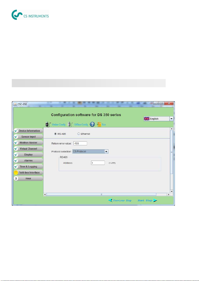
All device settings of DS 350/330 can be done in a convenient way through the configuration soft-
ware CSC-350 (see chapter 4.).
3. Settings on DS 350/330
There are many settings available, but the focus here is on the Flied-bus Interface settings.
RS-485 settings:
Return error value: Is the value the salve device will return as a measurement value in
case of any error condition.
Protocol selection: Please choose CS Protocol if using CSM software, chose Modbus
if device is connected to a Modbus network.
(090) 696-6535 or (093) 820-5599
www.gotek.com.vn
Gotek Vietnam Ltd.

DS 350/330 ICOM DS 350/330 ICOM
DS 350/330 ICOM English, V1.2, 17.12.12 DS 350/330 ICOM English, V1.2, 17.12.12
0970 0060 0970 0060 1712
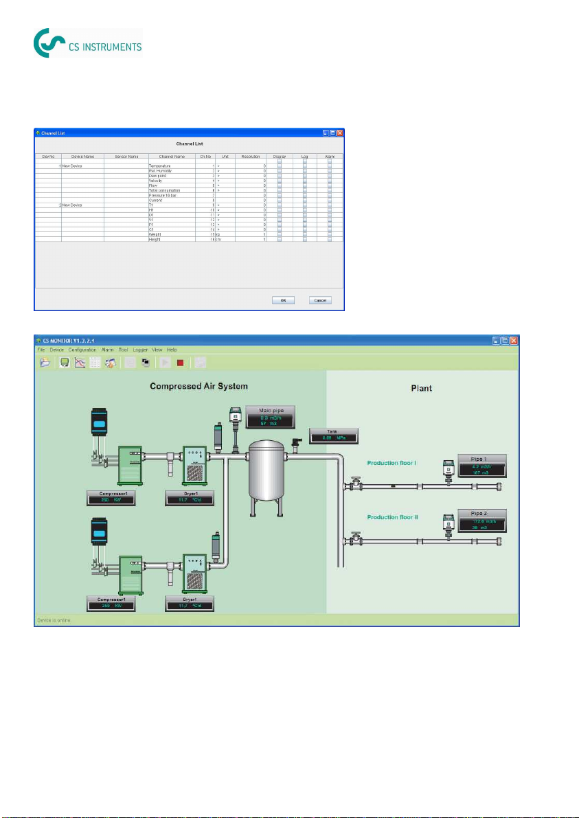
In the Channel list, all
measurement channels will
be listed. User can select
those measurement he
wants to show on the
screen and those he wants
to do data logging.
User can also input a name
for every sensor.
Select “Device —-> Go online” to show online measurement as shown above. Press and hold
the left mouse button, drag the mouse and move the meter windows to proper location, release
the mouse to confirm moving.
The next step is to select in the channel list the measurement channels which should be displayed
on the screen and which channels should be logged or have an alarm monitoring.
Please also consider, that only one software can communicate with the DS 350/330, it’s not
possible to start multiple software form different PC at the same time. This also applies to
Modbus, where only one Modbus-master can communicate at the same time.
Address: Each device on the RS-485 network needs to have a unique de
vice address. Please ensure that address 0 is not used and that
there are no duplicated addresses.
Ethernet settings:
Return error value: Is the value the salve device will return as a measurement value in
case of any error condition.
Protocol selection: Please choose CS Protocol if using CSM software, chose Modbus
if device is connected to a Modbus network.
Get IP config automatically Selecting this option will assign the DS 350/330 an IP address
through the network router. This is convenient but not a recom-
mended choice in industrial networks. We recommend to choose a
fix IP address.
Use the following IP…. Enter the fix IP address here
(090) 696-6535 or (093) 820-5599
www.gotek.com.vn
Gotek Vietnam Ltd.
DS 350/330 ICOM DS 350/330 ICOM
DS 350/330 ICOM English, V1.2, 17.12.12 DS 350/330 ICOM English, V1.2, 17.12.12
0970 0060 0970 0060 1316
A 'Device List' dialog will then display
all DS350/330 found in the RS-485
network. Choose the one you want to
connect, then click 'Select'.
Please note: CSM-S can only connect
to one DS 350/330 at a time. CSM-M
can connect to several DS 350/330 at
the same time.
Choose “Configuration->Device list”
from the menu to open Device List
Dialog.
Click “Auto Detect” to detect all devices
connected.
CSM-M software is capable to com-
municate with up to 30 DS 350/330 at
the same time. After clicking “Auto
Detect” button, device list will display
all DS350/330 found in the LAN. Click
“OK”.
Note: “Auto Detect” only needs to be
done once unless hardware changed.
RS-485 device list dialog
Ethernet device list dialog
Printing the Modbus slave register table
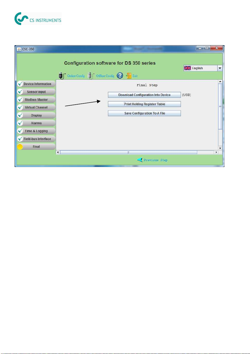
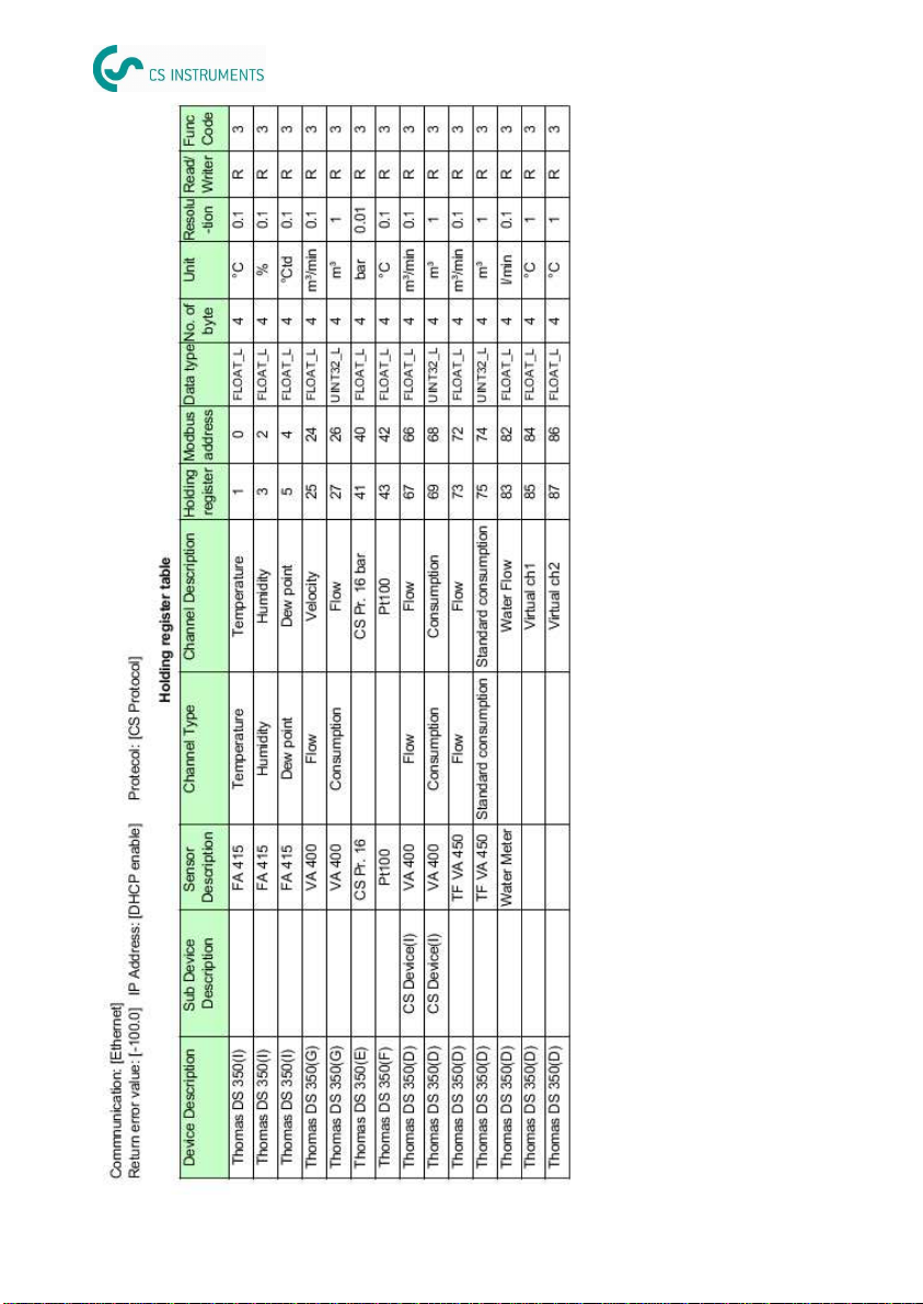
After the configuration of a DS 350/330 is finished, one of the final steps is to print the Modbus
register table. This table describes all Modbus register addresses and it’s measurement value
contents. According to the table the Modbus master device needs to be programmed.
The next page shows an example of a Modbus register table and its contents.
(090) 696-6535 or (093) 820-5599
www.gotek.com.vn
Gotek Vietnam Ltd.
DS 350/330 ICOM DS 350/330 ICOM
DS 350/330 ICOM English, V1.2, 17.12.12 DS 350/330 ICOM English, V1.2, 17.12.12
0970 0060 0970 0060 1514
Following software is available for download from the company web page
www.csinstrument.com:
CSC-350 Configuration software for DS 350 / 330 / 320
CSM-S Single device data acquisition and analyzes software
CSM-M Multiple device data acquisition and analyzes software
After downloading of the files, please follow the instructions of the installation software.
4. Installation of Software
This chapter describes the basic configuration wettings in the software in order to communicate
with the devices. Start CSM-S or CSM-M and choose “Configuration->Communication” from
the menu to open Configuration Dialog. Select the appropriate communication channel.
4.1 Configuration of CSM-S and CSM-M
The DS 350/330 series has 3 different
selections: Ethernet, RS-485 or USB. For
RS-485 it’s required to additionally select
COM port number. Then click 'OK'.
Note: if you don’t know which COM port
number should be selected please select
“Help —> Help Contents” to read related
section in the help file.
Example of a Modbus register table
(090) 696-6535 or (093) 820-5599
www.gotek.com.vn
Gotek Vietnam Ltd.

DS 350/330 ICOM DS 350/330 ICOM
DS 350/330 ICOM English, V1.2, 17.12.12 DS 350/330 ICOM English, V1.2, 17.12.12
0970 0060 0970 0060 1316
A 'Device List' dialog will then display
all DS350/330 found in the RS-485
network. Choose the one you want to
connect, then click 'Select'.
Please note: CSM-S can only connect
to one DS 350/330 at a time. CSM-M
can connect to several DS 350/330 at
the same time.
Choose “Configuration->Device list”
from the menu to open Device List
Dialog.
Click “Auto Detect” to detect all devices
connected.
CSM-M software is capable to com-
municate with up to 30 DS 350/330 at
the same time. After clicking “Auto
Detect” button, device list will display
all DS350/330 found in the LAN. Click
“OK”.
Note: “Auto Detect” only needs to be
done once unless hardware changed.
RS-485 device list dialog
Ethernet device list dialog
Printing the Modbus slave register table
After the configuration of a DS 350/330 is finished, one of the final steps is to print the Modbus
register table. This table describes all Modbus register addresses and it’s measurement value
contents. According to the table the Modbus master device needs to be programmed.
The next page shows an example of a Modbus register table and its contents.
(090) 696-6535 or (093) 820-5599
www.gotek.com.vn
Gotek Vietnam Ltd.
DS 350/330 ICOM DS 350/330 ICOM
DS 350/330 ICOM English, V1.2, 17.12.12 DS 350/330 ICOM English, V1.2, 17.12.12
0970 0060 0970 0060 1712
In the Channel list, all
measurement channels will
be listed. User can select
those measurement he
wants to show on the
screen and those he wants
to do data logging.
User can also input a name
for every sensor.
Select “Device —-> Go online” to show online measurement as shown above. Press and hold
the left mouse button, drag the mouse and move the meter windows to proper location, release
the mouse to confirm moving.
The next step is to select in the channel list the measurement channels which should be displayed
on the screen and which channels should be logged or have an alarm monitoring.
Please also consider, that only one software can communicate with the DS 350/330, it’s not
possible to start multiple software form different PC at the same time. This also applies to
Modbus, where only one Modbus-master can communicate at the same time.
Address: Each device on the RS-485 network needs to have a unique de
vice address. Please ensure that address 0 is not used and that
there are no duplicated addresses.
Ethernet settings:
Return error value: Is the value the salve device will return as a measurement value in
case of any error condition.
Protocol selection: Please choose CS Protocol if using CSM software, chose Modbus
if device is connected to a Modbus network.
Get IP config automatically Selecting this option will assign the DS 350/330 an IP address
through the network router. This is convenient but not a recom-
mended choice in industrial networks. We recommend to choose a
fix IP address.
Use the following IP…. Enter the fix IP address here
(090) 696-6535 or (093) 820-5599
www.gotek.com.vn
Gotek Vietnam Ltd.

DS 350/330 ICOM DS 350/330 ICOM
DS 350/330 ICOM English, V1.2, 17.12.12 DS 350/330 ICOM English, V1.2, 17.12.12
0970 0060 0970 0060 1118
5. Trouble shooting
5.1 Ethernet
Can not find any device or can not establish communication.
•
Check device connection. There are 2 lights at DS350/330 Ethernet interface. When DS
350/330 properly connected, the yellow one should be on indicating power supply is OK,
while green light should be blinking which indicate data transmission.
•
Check network cable. Make sure it's the right RJ45 Ethernet cable and connect properly.
Note that 'Link' light on the switching hub should be on.
•
Check if PC and DS 350/330 are on the same subnet.
•
Check if there exists a device or PC which has same IP address as the DS 350/330.
•
Make sure firewall settings on PC doesn't block DS 350/330 communication which uses port
6789.
•
Check if the firewall is closed on the PC
•
Make sure that the PC has installed only one Ethernet card
Communication is not stable.
•
Check and set static IP address for every device with the software tool (To install the tool,
please double click “CS Ethernet Device_Setup.exe” which can be found in the CD)
•
Check to make sure the speed of switching hub which DS350/330 connect to is 100M.
•
Check physical connection ( network cable ) making sure it's well connected.
•
Try to set communication option again in “Configuration —> Communication”.
•
Now try to communicate again.
•
If it still not working, try to reset DS350/330 by power it off and on again. And restart CS-
Monitor. Then retry the communication.
RS-485 Cable specification:
Impedance: 135 – 165 Ohm @ 3 to 20 Mhz
Cable capacity: < 30pF/m
Cable diameter: > 0.64 mm
Cross section: > 0.34 mm², conforms to AWG 22
Loop resistance: < 110 Ohm per km
Screening: Cu shielding braid or shielding braid and shielding foil
All device settings of DS 350/330 can be done in a convenient way through the configuration soft-
ware CSC-350 (see chapter 4.).
3. Settings on DS 350/330
There are many settings available, but the focus here is on the Flied-bus Interface settings.
RS-485 settings:
Return error value: Is the value the salve device will return as a measurement value in
case of any error condition.
Protocol selection: Please choose CS Protocol if using CSM software, chose Modbus
if device is connected to a Modbus network.
(090) 696-6535 or (093) 820-5599
www.gotek.com.vn
Gotek Vietnam Ltd.

DS 350/330 ICOM DS 350/330 ICOM
DS 350/330 ICOM English, V1.2, 17.12.12 DS 350/330 ICOM English, V1.2, 17.12.12
0970 0060 0970 0060 1910
5.2 RS-485
Cannot find any device or cannot establish communication
•
Check the USB-RS485 converter has correct cable connection to the net work.
•
Check each DS 350/330 has an unique address set.
Communication is not stable or lost during online reading
•
Check to ensure that only the last device on the RS 485 network has it’s termination resistor
network switched on.
•
Check to ensure bus cable must be laid at a distance of at least 20 cm from other cables.
•
Check that bus cable is below 1000 m, otherwise consider to install a repeater.
There are totally 6 poles on the terminal H for RS 485 network wiring. The pin function descrip-
tion is shown below.
2.3.2 RS-485 hardware setup
Pin No. Function
1 Shield signal for wiring to the next device
2 Data – signal for wiring to the next device
3 Data + signal for wiring to the next device
4 Shield signal for wiring to the previous device
5 Data – signal for wiring to the previous device
6 Data + signal for wiring to the previous device
Pin name
Shield out
Data -
Data +
Shield in
Data -
Data +
Through a RS-485 / USB converter the system is connected to a USB port of the office PC. For
easy wiring of a multiple device to RS485, DS 350/330 provides loop-through pins for connecting
to next device on the network. RS485 network requires a termination resistor network. At the last
device in the network the DIP switch must be set to the ON position, all other DS 350/330 re-
main in OFF position.
RS-485 cable:
Only cables according to the recommendations of EIA 485 standard should be used. A maxi-
mum of 30 devices may be connected to one segment. The bus cable must be laid at a dis-
tance of at least 20 cm from other cables. It should be laid in a separate, conductive, and
earthed cable trunk. It must be ensured that no potential differences occur between the individ-
ual devices on the bus.
(090) 696-6535 or (093) 820-5599
www.gotek.com.vn
Gotek Vietnam Ltd.

DS 350/330 ICOM DS 350/330 ICOM
DS 350/330 ICOM English, V1.2, 17.12.12 DS 350/330 ICOM English, V1.2, 17.12.12
0970 0060 0970 0060 920
8.0 APPENDIX
8.1 APPENDIX A – Modbus communication example
01 (0x01) Read coil status
Slave address 1 byte
Function code 1 byte
Starting address Hi 1 byte
Starting address Lo 1 byte
No. of points Hi 1 byte
No. of points Lo 1 byte
CRC 2 bytes
Slave address 1 byte
Function code 1 byte
Byte count 1 byte
Data coil 1 byte
: :
Data coil 1 byte
CRC 2 bytes
Request Response
03 (0x03) Read holding register
Slave address 1 byte
Function code 1 byte
Starting address Hi 1 byte
Starting address Lo 1 byte
No. of registers Hi 1 byte
No. of registers Lo 1 byte
CRC 2 bytes
Slave address 1 byte
Function code 1 byte
Byte count 1 byte
Register Hi 1 byte
Register Lo 1 byte
: :
Register Hi 1 byte
Register Lo 1 byte
CRC 2 bytes
Request Response
05 (0x05) Write single coil
Request Response
Slave address 1 byte
Function code 1 byte
Coil address Hi 1 byte
Coil address Lo 1 byte
Data Hi 1 byte
Data Lo 1 byte
CRC 2 bytes
Slave address 1 byte
Function code 1 byte
Coil address Hi 1 byte
Coil address Lo 1 byte
Data Hi 1 byte
Data L 1 byte
CRC 2 bytes
2.3 Hardware setup
2.3.1 Ethernet hardware setup
Internal RJ45 connector External RJ45 connector (IP65)
Connect Ethernet cable and mount bend protection sleeve
Ethernet cable:
An Ethernet cable with category 5 or better is applicable and the maximum cable length is 100
meter between DS 350/330 and the connected HUB or computer.
(090) 696-6535 or (093) 820-5599
www.gotek.com.vn
Gotek Vietnam Ltd.
This manual suits for next models
1
Table of contents
Other CS Instruments Industrial Equipment manuals

Popular Industrial Equipment manuals by other brands

Festo
Festo ELGA-BS-KF-80 instructions

Bosch
Bosch 0 986 613 461 Original instructions

Horizon Fuel Cell Technologies
Horizon Fuel Cell Technologies H-300 user manual

schmalenberger
schmalenberger FLUVO xanas 1,5 Operator's manual

Rego-fix
Rego-fix reCool RCR/ERAX Maintenance and operating manual

Wilo
Wilo Wilo-Star-Z NOVA Installation and operating instructions


