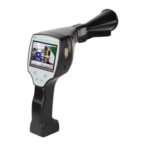
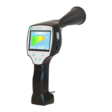
CS Instruments LD 500 User manual

EN- English
LD500 V2.03 Seite 1von 67
Instruction manual
Leak detector with camera
LD 500 / LD510

Table of Content
LD500 V2.03 Seite 2von 67
1Table of Content
2SAFETY INSTRUCTIONS ................................................................................................................................................. 5
2.1 GENERAL SAFETY INSTRUCTION................................................................................................................................................ 5
2.2 USING OF CLASS 2LASER........................................................................................................................................................ 5
3SERVICE AND MAINTENANCE ....................................................................................................................................... 6
4ENVIRONMENTAL PROTECTION.................................................................................................................................... 6
5INTENDED USE.............................................................................................................................................................. 6
6TECHNICAL DATA LD500 ............................................................................................................................................... 7
7IDENTIFICATION ........................................................................................................................................................... 7
7.1 NAME PLATE ....................................................................................................................................................................... 7
7.2 LASER WARNING LABEL .......................................................................................................................................................... 7
8DEVICE COMPONENTS AND CONTROLS........................................................................................................................ 8
8.1THE LD 500........................................................................................................................................................................ 8
9OVERVIEW AND APPLICATION DESCRIPTION OF THE DIFFERENT SENSOR TYPES.......................................................... 9
9.1 ASSEMBLY WITH ACOUSTIC TRUMPET ..................................................................................................................................... 10
9.2 ASSEMBLY WITH FOCUS TUBE WITH FOCUS TIP.......................................................................................................................... 10
9.3 ASSEMBLY WITH GOSSENECK ................................................................................................................................................ 11
9.4 ASSEMBLY WITH PARABOLIC MIRROR ..................................................................................................................................... 11
10 START-UP / / APPLICATION LD 500............................................................................................................................. 12
10.1 SWITCH ON .................................................................................................................................................................. 12
10.2 HEADPHONE VOLUME UP /VOLUME DOWN ...................................................................................................................... 12
10.3 SENSITIVITY LEVEL.......................................................................................................................................................... 12
10.4 LASER ON/OFF ............................................................................................................................................................. 12

Table of Content
LD500 V2.03 Seite 3von 67
11 OPERATION ................................................................................................................................................................ 13
11.1 INITIALIZATION.............................................................................................................................................................. 13
11.2 SCREEN LECKAGE........................................................................................................................................................... 14
11.3 HOME MENU LD 500..................................................................................................................................................... 15
11.3.1 Configuration of LD500 ................................................................................................................................... 16
11.3.1.1 Sensortype selection (Measuring tool).........................................................................................................................17
11.3.1.2 Storing of the measurement.........................................................................................................................................18
11.3.1.3 Parameter / Meas. Point (Re-Check) ............................................................................................................................18
11.3.1.4 Fault description...........................................................................................................................................................19
11.3.1.5 Storing measurement data to internal SD-card............................................................................................................19
11.3.2 Export/Import.................................................................................................................................................. 20
11.3.2.1 Export ...........................................................................................................................................................................21
11.3.2.1.1 Export „Leakage Data“ ............................................................................................................................................21
11.3.2.1.2 Export of System settings........................................................................................................................................22
11.3.2.2 Import...........................................................................................................................................................................23
11.3.2.2.1 Import of system settings........................................................................................................................................23
11.3.2.2.2 Import new measurement tool ...............................................................................................................................24
11.3.2.3 Export / Import Customer database.............................................................................................................................25
11.3.3 View bitmaps................................................................................................................................................... 26
11.3.4 Device Settings ................................................................................................................................................ 27
11.3.4.1 Passwort-Einstellung ....................................................................................................................................................27
11.3.4.2 Device Settings .............................................................................................................................................................28
11.3.4.2.1 Language .................................................................................................................................................................28
11.3.4.2.2 Date & Time.............................................................................................................................................................29
11.3.4.2.3 SD-Card....................................................................................................................................................................29
11.3.4.2.4 System update.........................................................................................................................................................30
11.3.4.2.5 Check for Updates ...................................................................................................................................................30
11.3.4.2.6 Update Channels .....................................................................................................................................................31
11.3.4.2.7 Factory Reset...........................................................................................................................................................31
11.3.4.2.7.1 Reset to default settings..................................................................................................................................31
11.3.4.2.8 Unique USB ID .........................................................................................................................................................31
11.3.4.2.9 Calibration of touchpanel........................................................................................................................................32
11.3.4.2.10 Set backlight brightness.........................................................................................................................................33
11.3.4.2.11 Cleaning.................................................................................................................................................................34
11.3.4.2.12 System-Status ........................................................................................................................................................34
11.3.4.2.13 About LD 500 .........................................................................................................................................................34
12 CHARGING THE BATTERIES ......................................................................................................................................... 35

Table of Content
LD500 V2.03 Seite 4von 67
13 LD 510 ........................................................................................................................................................................ 36
13.1 SELECTION EXTERNAL SENSOR .......................................................................................................................................... 36
13.2 INPUT SIGNALS OF EXT.SENSOR LD510 ............................................................................................................................. 37
13.3 CABLE CROSS SECTION .................................................................................................................................................... 37
13.3.1 Sensor circuit points/Output signal:................................................................................................................ 37
13.4 CONNECTION DIAGRAMS FOR DIFFERENT SENSOR TYPES......................................................................................................... 38
13.4.1 Connector pin assignment for all sensors at PI 500........................................................................................ 38
13.4.2 Connection for CS dew point- and consumption sensors, series FA/VA 5xx .................................................... 39
13.4.3 Connection with RS485.................................................................................................................................... 39
13.4.4 Three- and four-wire power supply 0 - 1/10/30 VDC ...................................................................................... 39
13.4.5 Analogue two-, three-, and four-wire current signal....................................................................................... 40
13.4.6 Two-, three- and four-wire connector pin assignments for PT100/PT1000/KTY81......................................... 41
13.5 DEW POINT SENSOR FA 500 /FA 510 (RS 485 MODBUS).................................................................................................. 42
13.5.1 Settings Dew point sensor FA 500 / FA 510..................................................................................................... 43
13.5.1.1 Unit selection for temperature and humidity...............................................................................................................43
13.5.1.2 Definition of the System pressure (relative pressure value).........................................................................................43
13.5.1.3 Definition of Reference pressure (absolute pressure value) ........................................................................................44
13.5.1.4 Field adjustment...........................................................................................................................................................44
13.5.1.5 More Settings Analogue output 4-20mA......................................................................................................................45
13.6 FLOW SENSOR OF TYPE VA 500 /VA 520 /VA 550 /VA 570 (RS 485 MODBUS) ................................................................. 46
13.6.1 Settings for Flow sensor VA 5xx ...................................................................................................................... 47
13.6.1.1 Diameter settings (only for VA 500 or VA 550).............................................................................................................47
13.6.1.2 Gas Constant settings ...................................................................................................................................................48
13.6.1.3 Definition of the reference conditions .........................................................................................................................49
13.6.1.4 Definition Unit of flow and velocity..............................................................................................................................49
13.6.1.5 Definition consumption counter value and consumption unit.....................................................................................50
13.6.1.6 Settings analogue output 4-20mA of VA 5xx ................................................................................................................51
13.6.1.7 Settings Pulse / Alarm output of VA 5xx.......................................................................................................................52
13.6.1.8 Settings ZeroPoint or Low Flow Cut off for VA 5xx.......................................................................................................54
13.7 TYPE MODBUS.............................................................................................................................................................. 55
13.7.1 Selection and activation of Sensor-Type Modbus ........................................................................................... 55
13.7.1.1 Modbus Settings...........................................................................................................................................................55
13.8 DATA LOGGER SETTINGS ................................................................................................................................................. 59
14 SCOPE OF DELIVERY.................................................................................................................................................... 63
15 APPENDIX................................................................................................................................................................... 63

Safety instruction
LD500 V2.03 Seite 5von 67
2Safety instructions
About this document
•Read this documentation carefully and familiarize yourself with the product
before using it. Pay particular attention to the safety and warning instructions to
prevent injury and product damage.
•Keep this documentation handy for future reference.
•Share this documentation with future users of the product.
2.1 General safety instruction
•The product is to be used only in accordance with the intended purpose and
within the parameters specified in the technical data. Do not use force for
operation.
•Never measure with the device at or near live/energized parts!
•During leak detection on electrical systems, please maintain a sufficient safety
distance to avoid dangerous electric shocks!
•Avoid any direct contact with hot and/or rotating parts.
•Always switch on the device before putting on the headphones! At high signal
levels (bar graph headphones in the red area), the volume can be correspondingly
large. The sensitivity setting can be used to reduce the volume.
•Observe the prescribed storage and operating temperatures.
•In case of improper handling or violence, the warranty claims are lost.
•Interventions on the device of any kind, unless they correspond to the intended
and described procedures, lead to the expiration of warranty and to the
disclaimer.
•The device is intended solely for the described purpose.
2.2 Using of class 2 laser
•Never point the laser directly towards persons!
•Absolutely avoid a direct irradiation of the eyes of humans and animals!
•If a person‘s eyes are exposed to class 2 laser radiation, they should shut their
eyes and immediately move away from the beam
•Do not stare into the beam
•Laser module: corresponds to DIN EN 60825-1: 2014 Class 2 (<1mW / 635nm)
•Laser output point trumpet and parabolic mirror:
Laseraustrittstelle
Laser output point
Laseraustrittstelle
Laser output point

Safety instruction
LD500 V2.03 Seite 6von 67
3Service and maintenance
Service and maintenance work must only be carried out by authorized personnel.
4Environmental protection
•Disposal of defective batteries / dead batteries according to the valid legal
regulations.
•After the end of the useful life, take the product to the separate collection
for electrical and electronic equipment (observe local regulations) or return
the product to CS Instruments GmbH & Co.KG for disposal.
CS Instruments GmbH & Co.KG makes no warranty as to its suitability for any particular
purpose and assumes no liability for any errors contained in this manual. Nor for
consequential damages in connection with the delivery, performance or use of this device.
5Intended use
The LD 500 is a leak detector for quick and reliable leak detection in/on compressed air
systems.
The LD500 leak detector evaluates the ultrasonic waves generated by the leakage based on
distance and pressure.
It is solely designed and constructed for the intended use described here and may only be
used for this purpose.
The user must verify that the device is suitable for the intended use. The technical data listed
in this datasheet are binding.
Improper handling or operation outside the technical specifications is not permitted. Claims
of any kind for damages arising from improper use are excluded.

Technical data
LD500 V2.03 Seite 7von 67
6Technical data LD500
Dimension
263 x 96 x 280 mm (incl. PreAmp module and acoustic trumpet)
Weight
0,55 kg incl. PreAmp module and acoustic trumpet ,
complete set with transportation case ca.3,5 kg
Frequency range
40kHz (+/- 2kHz)
Power supply
Internal 7.4 V lithium-ion battery
Operating time
> 9 h (continuous operation)
Operating temperature
-5 °C to +40 °C
Charging
Ext. battery charger (included in the scope of delivery)
Charging time
approx. 1.5 h
Storage temperature
-20 °C to +50 °C
Laser
Laser class 2 (< 1mW / 635nm) according IEC 60825-1:2014
Connections
3.5 mm jack for headphones,
power jack for connecting an external charger
USB Connection
Display
3.5“-Touchpanel TFT transmissiv
Interface
USB for data export / -import, SW update etc.
Datalogger
8 GB-Memory card (Micro SD Class 4)
Sensitivity
min: 0,1l/min at 6bar / 5m Distance
7Identification
7.1 Name plate
7.2 Laser warning label

Device controls
LD500 V2.03 Seite 8von 67
8Device components and controls
8.1 The LD 500
3.5mm jack for the
headphone
Acoustic trumpet
Camera
USB connection
Plug-in connection for
power supply (battery
charger socket)
Save button
Volume (+/-)
On/Off button
Foil keypad (4 buttons)
Unlock button for preamp
module
Preamp module
3.5" TFT colour display
with touch panel

Device components and controls
LD500 V2.03 Seite 9von 67
9Overview and application description of the different sensor types
Acoustic trumpet (standard tool)
Straightening tube
The acoustic trumpet bundles incident ultrasonic
waves, thereby extending the range of the device. This
behaviour makes it ideal for medium distances.
The leakage can be heard from large distances, for
precise detection, the user must approach the leakage
and consistently follow the "loudest" point. Individual
compressed air components are then checked for
precise detection.
Quantification distance (distance) 1 –6 m
Use of acoustic trumpet:
•Average distance to pipe/component 0.2 - 6 m
•Low interfering noise
•Leakage freely accessible
•Use at distances of up to 6 metres if no
parabolic mirror available
The straightening tube permits only very few ultrasonic
waves to pass in the direction of the ultrasonic transducer,
allowing leakages to be located very precisely.
For this reason, the use of the straightening tube is
recommended for small distances, for the precise detection
of the corresponding leakage.
Quantification distance: 0…0,2 m
Use of focus tube:
•Short distance to pipe/component 0.05 m
•Pipe/component freely accessible
•Pipes and components to be inspected are very
close together
•Medium to high noise
•Use when no gooseneck available
Gooseneck
Parabolic mirror
The gooseneck should be used if the pipes and
components to be inspected are physically very close.
In addition, the shape of the gooseneck can be flexibly
adapted to easily inspect hard-to-reach pipes and
components.
The sensitivity of the gooseneck has been reduced to
dampen noise. This makes it ideal for target-ed, local
testing of compressed air components at high noise
levels, for example in systems using pneumatic
cylinders and in compressed air distribution cabinets
Quantification distance →0 …0.05m
Use of gooseneck:
•Short distance to pipe/component 0.05 m
•Leakage not freely accessible
•Medium to high ultrasonic noise
•Pipes and components to be inspected are
very close together
The parabolic mirror bundles horizontally incident
ultrasound in its focal point where the ultrasonic transducer
is located. On the one hand, this leads to a considerable
amplification of the measured ultrasound (high range) and,
on the other hand, to a very precise directional behaviour,
since ultra-sound that does not incident horizontally is
reflected by the reflector.
The combination of these two characteristics enables the
parabolic mirror to precisely locate leaks at large distances.
Quantification distance →3 –12 m
Use of parabolic mirror:
•Large distance to pipe/components 3 –15 m
•Interfering noise
•Leakage not freely accessible (behind a fence)
•Near leaks (superimposition))

Device components and controls
LD500 V2.03 Seite 10 von 67
9.1 Assembly with acoustic trumpet
The acoustic trumpet allows acoustic amplification by bundling the sound waves and specifies the
location of the leak. Due to the special construction of the integrated laser pointer is still usable. The
camera is integrated on the bottom of the acoustic trumpet and is electrically connected to the
preamplifier module via the jack plug.
Assembling is done by plugging the individual components until easy locking audible (plug in to the
stop).
The components are removed in the reverse order; for unlocking the preamplifier module, the release
button must also be pressed.
9.2 Assembly with focus tube with focus tip
The focus tube with focus tip is used to detect very small leaks, to accurately locate them.
Just like the acoustic trumpet, the tube can be plugged into the preamplifier with ultrasonic receiver.
The use of the camera is no longer possible.
The components are removed in the reverse order; for unlocking the preamplifier module, the release
button must also be pressed.

Device components and controls
LD500 V2.03 Seite 11 von 67
9.3 Assembly with Gosseneck
Due to its flexibility, the gooseneck tool is used for punctual measurements in hard-to-reach areas.
Connection to the LD 500 is via the supplied spiral cable, see Figure 10.
It is no longer possible to use the camera.
To remove the component, remove the connection cable by pressing the release button on both sides
and pulling off the cable.
9.4 Assembly with Parabolic mirror
The parabolic mirror is used for measurements at greater distances as well as for high requirements
regarding selectivity and location of leakage positions.
Connection to the LD 500 is via the supplied spiral cable, see Figure 11.
To remove the component, remove the connection cable by pressing the release button on both sides
and pulling off the cable.
Note: To use the parabolic mirror and gooseneck, these components must be activated in the LD 500
during initial commissioning in order to save the component-specific adjustment parameters. If
this has not already been done ex-works, the data for this is supplied via USB stick. For the
activation (parameter import), see chapter 11 Operation here in Sub chapter "Export / Import".“.

Commissioning
LD500 V2.03 Seite 12 von 67
10 Start-up / / Application LD 500
Please first observe the safety instructions in Chapter 2
10.1 Switch on
Hold down the power button for about 1 second, the power will turn on, and a start-up sequence will
appear on the display. Pressing the button again switches the device off again.
On-Off button, see device components and controls
10.2 Headphone Volume Up / Volume Down
The volume up and volume down buttons in the headset can be increased or decreased in 16 steps.
Continuously pressing the button automatically increases / decreases the value.
Volume up / down buttons for headphone volume, see device components and controls
Please make sure the headphone level is <50% before putting on the headphones.
10.3 Sensitivity level
Ultrasound levels can be understood as a "loudness" of the leakage.
With the “Sensitivity" button, the sensitivity of the LD500 can be adjusted to the environment, which
strongly influences the acoustic behaviour of the device and increases or decreases the valid value
range. A reduction in sensitivity reduces the range of the leakage reading but the "responding area",
indicated by the circle in the display, also gets smaller, which considerably simplifies detection.
Sensitivity levels
0 –60 dB = Highest sensitivity level of the device (use with small leaks and no noise), selection with the
"HiSn" button or the "Sensitivity" button
10 –70 dB = Leakages and noises get "less noisy", the range is reduced.
20 –80 dB = Leakages and noises get "less noisy", the range is reduced.
30 –90 dB = Leakages and noises get "less noisy", the range is reduced.
40 –100 dB = Most insensitive stage (large leaks, many noises →for heavy-duty application)
By default, the LD500 is set to the auto function and will automatically switch between levels (10 –70 dB
to 40 –100 dB).
10.4 Laser On/Off
The laser pointer can only be switched on or off via the laser on / off button in the display (not via
the membrane keypad). When switched on, the display shows a laser warning symbol.
Laser „On“
Icon
Please note the warnings for laser
operation!
Avoid direct / indirect (via reflexion)
irradiation of the eyes in humans and
animals!

Operation
LD500 V2.03 Seite 13 von 67
11 Operation
The operation is largely self-explanatory and menu-driven via the touch panel.
The selection of the respective menu items occur via short "tapping" with the finger or a soft round pen.
Attention: Please use no pens or other objects with sharp edges!
The foil can be damaged!
Inputs or changes can be made with all white deposit fields
11.1 Initialization
After switching on the LD 500, the
initialization takes place and then switch
to leakage display

Operation
LD500 V2.03 Seite 14 von 67
11.2 Screen Leckage
The following picture shows and describes the display elements.
Date / Time:
Battery condtion indicator
Battery condition:
22%
Power supply connected and battery is charging:
Displayed values for:
•Signal-Level in dB
•Leakage size
•Leakage costs per year
Laser „On“ Icon
Date/ Time and battery
condition indicator
Bar graph of Signal level
LeakTag number
Actual camera image
Laser „On/Off“ button
Setting button
Store button for
Measurement
Mode switch button
Auto or manual (HiSn)
Sensivity level button
Home Menu
button

Operation
LD500 V2.03 Seite 15 von 67
11.3 Home menu LD 500
The operation is largely self-explanatory and menu-driven via the touch panel.
The selection of the respective menu items occur via short "tapping" with the finger or a soft round pen.
Attention: Please use no pens or other objects with sharp edges!
The foil can be damaged!
Before the leakage search is started, the device must be configured. The user can access the menu by
clicking the "Home" button. The following figure shows the Home "Menu".
Home
With the button „Home“ you access the basic
menu of the LD 500.
Return to measurement by pressing
„Leakage“ –button.

Operation
LD500 V2.03 Seite 16 von 67
11.3.1 Configuration of LD500
Home
➔
Configuration
Home
➔
Configuration
➔
Parameter
In the configuration settings the unit system can be selected and
the required parameters entered, this to calculate the leakage
costs per year.
➔Selection of ISO or US unit system
➔Call up the text field "Costs/ 1000 m³" to define the costs.
There are 2 variants to choose from:
•Standard: Cost per 1000 volume units
Enter cost and the currency
Default value: 19 € / 1000 m³ or
0.538€/1000cf
•Expert: Here you can see in detail the electricity
ocosts / KWh and define the specific power
of the system. For the specific power 3
pre-defined asset values are created and
a user defined input field for the
individual input is made available.
➔Enter working hours per year
➔Sensor type
Selection of the sensor type according to the application and
ambient conditions, see therefor chapter 6.
➔Pressure (line pressure in bar)
➔Distance (distance to leakage in m)
Depending on the selected sensor type, there are up to 4 pre-
defined pressure and distance values that can be selected
directly as well as two fields (white) in which values for the
pressure and the distance are freely selected..
The pressure can be set variably between 1 - 10 bar.
For the different sensor types different minimum and
maximum distances from the LD500 to the leakage are
defined to calculate valid leakage loss and costs per year.
These distances must be strictly adhered to.

Operation
LD500 V2.03 Seite 17 von 67
Home
➔
Configuration
➔
Meas.Point
11.3.1.1 Sensortype selection (Measuring tool)
In order to simplify the leak detection for the user, various tools for different measuring conditions have
been developed .
The distances mentioned for quantifying the leakage always refer to the front of the respective tool.
If the parabolic mirror / gooseneck has been ordered separately, the application data for the
devices must be loaded into the LD500 first. Data is supplied via USB stick.
Import:
Home →Export/Import →Import new Tool →Parabolic Mirror / Gooseneck Serial Number
The measuring point is stored for each leakage in its journal
data. These can be seen later in the leakage report in the
software.
➔LeakTag: will be automatically increased by one after
storing a measurement.
All information about the measuring point can be changed
by selecting the corresponding text field or the stored
measuring points can be loaded from the internal database.
Then a menu opens with the available / saved entries.
When selecting a saved value, select it (highlighted in green)
and then take over with „OK“.
If a new entry is necessary, the input menu opens after
pressing the „new“ button.
Input is accepted via „OK“.
This procedure is analogous to enter the information for
company, building and location.
Using the „delete“ button, individual entries can be deleted
too.

Operation
LD500 V2.03 Seite 18 von 67
11.3.1.2 Storing of the measurement
To store the measurements please press either the button „Store“on the foil keypad, see chapter
Device components and controls , or by button „Store“in the display.
All data are stored on to the internal SD card.
The measurement data, the measurement point and the image of the measurement point are saved as a
journal, which can be exported later and a report can be created with the CS Leak Reporter (order no.:
0554 0105).
After pressing one of the two „Store“keys, the corresponding information for the measuring point must
be completed. The measuring point information of the last stored storage (company, building and
location) is displayed, the numbering of the leaking tag is increased by 1.
e.g .:
11.3.1.3 Parameter / Meas. Point (Re-Check)
Store
➔
Parameter
Store
➔
Meas. Point
At this point, it is again possible to check and correct the parameters „Pressure" and „Distance" and the
measuring point.
Changing the parameters gives new values for leakage and cost.
Execution of the corrections see description chapter 9.3.1
If necessary, fill out the Leak
Tag-form and attach it to the
measuring location.
Please use correct Leak Tag-
number.

Operation
LD500 V2.03 Seite 19 von 67
11.3.1.4 Fault description
Store
➔
Textfield Fault Description
11.3.1.5 Storing measurement data to internal SD-card
Store
➔
store
In addition to the details of the measuring point
with company, building and location, it is
possible to enter a fault decription (up to 32
characters).
To do this, select the text field „Fault
description“and enter the comment.
Here you can enter "short descriptions" for the
individual fields.
The entries are also stored in an internal
database so that they can be used again and
again.
Some suggestions are already saved on delivery.
See left, for example the selection for the field
"Leak. Element".
Before final storage of the measurement on the
internal SD card, a summary is created and the
correctness is queried once more for safety.
Storage is done with the „Yes“key.
The „No“key returns to the previous menu.

Operation
LD500 V2.03 Seite 20 von 67
11.3.2 Export/Import
With Home
→
Export / Import,
•Recorded "Leakage data" can be transferred to a USB stick
•System settings can be exported as well as imported
•Measuring points (company, building and location data) can be exported as well as imported.
•Non-activated optional measurement tools can be activated/loaded.
Other manuals for LD 500
2
This manual suits for next models
2
Table of contents
Other CS Instruments Security Sensor manuals
