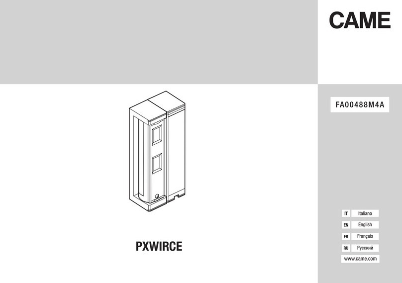
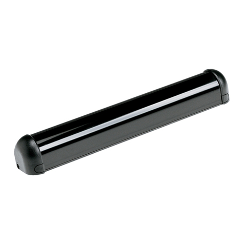
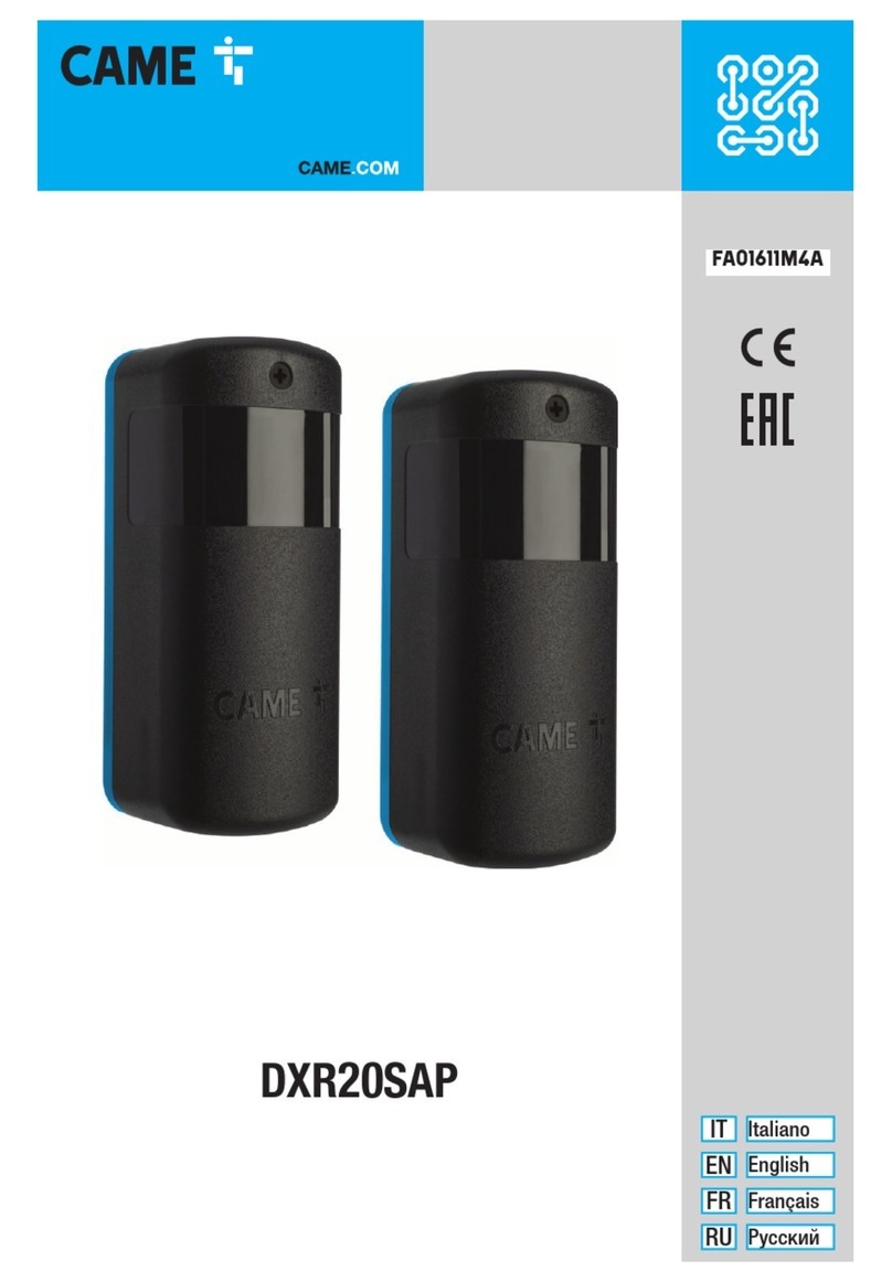
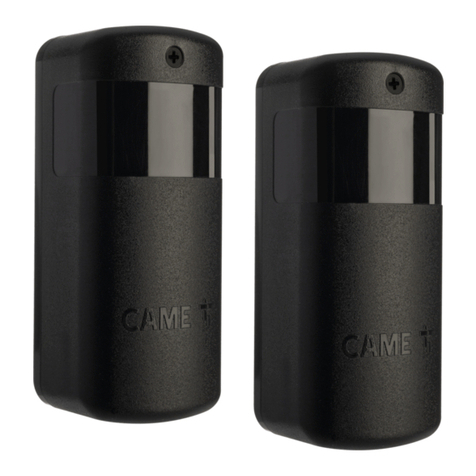
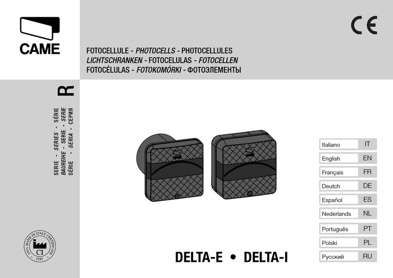
CAME DXR20CAP User manual

806TF-0030 806TF-0040
806TF-0050
FA01650M4A
IT Italiano
EN English
FR Français
RU Pусский

2- FA01650M4A - 10/2022 - © CAME S.p.A. -
A
27
90
46
108
35,5
B

10 11 SY
ON
+-
41
2
3
ON
41
3
2
MAX
20 m
MAX
10 m
10 11 OUT
+-
ON
3
1
2
ON
4
41
32
NC
10 11 OUT
NO
10 11 OUT
TX
RX
C

4- FA01650M4A - 10/2022 - © CAME S.p.A. -
-5°
0°
+5°
180°
0°
D

5- FA01650M4A - 10/2022 - © CAME S.p.A. -
1 2 3 4
RX TX
10 11
2 CX
Control Board
10 11
+ -
OUT
1 2 3 4
10 11 SY
+ -
E
TX
TS 10
10 11 SY
+ -
10 11 2 CX
10 11
+ - OUT
RX
F
RX1
TX2
TX1
RX2
1 2 3 4 1 2 3 4
1 2 3 4 1 2 3 4
10 11
Control Board
10 11 SY
+ -
10 11
+ -
OUT
10 11 SY
+ -
10 11
+ -
OUT
G

6- FA01650M4A - 10/2022 - © CAME S.p.A. -
RX-1
1 2 3 4
RX-3
1 2 3 4
RX-4
1 2 3 4
RX-5
1 2 3 4
RX-6
1 2 3 4
RX-7
1 2 3 4
RX-8
1 2 3 4
RX-2
1 2 3 4
TX-1
1 2 3 4
TX-3
1 2 3 4
TX-4
1 2 3 4
TX-5
1 2 3 4
TX-6
1 2 3 4
TX-7
1 2 3 4
TX-8
1 2 3 4
TX-2
1 2 3 4
10 11
+ - OUT 10 11
+ - OUT 10 11
+ - OUT 10 11
+ - OUT 10 11
+ - OUT 10 11
+ - OUT 10 11
+ - OUT 10 11
+ - OUT
10 11
10 11 SY
+ -
10 11 SY
+ - 10 11 SY
+ -
10 11 SY
+ - 10 11 SY
+ - 10 11 SY
+ - 10 11 SY
+ - 10 11 SY
+ -
H

7- FA01650M4A - 10/2022 - © CAME S.p.A. -
RX5
RX6
RX7
RX8
TX1
TX2
TX3
TX4
RX1
RX2
RX3
RX4
TX5
TX6
TX7
TX8
I

8- FA01650M4A - 10/2022 - © CAME S.p.A. -
ITALIANO
Avvertenze generali per l'installatore
Leggere attentamente le istruzioni prima di iniziare l’installazione ed eseguire gli interventi
come specificato dal costruttore. • L’installazione, la programmazione, la messa in
servizio e la manutenzione devono essere eettuate da personale qualificato ed esperto
e nel pieno rispetto delle normative vigenti. • Prima di eettuare qualunque operazione
di pulizia, manutenzione o sostituzione di parti, togliere l’alimentazione al dispositivo. •
Il prodotto deve essere destinato solo all’uso per il quale è stato espressamente studiato
e ogni altro uso è da considerarsi pericoloso. • Il produttore non può essere considerato
responsabile per eventuali danni causati da usi impropri, erronei ed irragionevoli. • Il
prodotto nella confezione originale del produttore può essere trasportato solo al chiuso
(vagoni ferroviari, container, veicoli chiusi). • Nel caso di malfunzionamento del prodotto,
interromperne l'uso e contattare il servizio clienti all’indirizzo https://www.came.com/
global/en/contact-us o al numero telefonico indicato sul sito.
La data di fabbricazione è indicata nel lotto di produzione stampato
sull’etichetta prodotto. Se necessario, contattateci all’indirizzo https://www.came.
com/global/en/contact-us.
Le condizioni generali di vendita sono riportate nei listini prezzi uciali Came.
Riferimenti Normativi
Il fabbricante, CAME S.p.A, dichiara che il prodotto descritto in questo manuale, è
conforme alla Direttiva 2014/53/UE.
Il testo completo della dichiarazione di conformità UE è disponibile al seguente indirizzo
internet: www.came.com.
Dismissione e smaltimento
Non disperdere nell’ambiente l’imballaggio e il dispositivo alla fine del ciclo di vita,
ma smaltirli seguendo le norme vigenti nel paese di utilizzo del prodotto. I componenti
riciclabili riportano simbolo e sigla del materiale.
I DATI E LE INFORMAZIONI INDICATE IN QUESTO MANUALE SONO DA RITENERSI
SUSCETTIBILI DI MODIFICA IN QUALSIASI MOMENTO E SENZA OBBLIGO DI PREAVVISO.
LE MISURE, SE NON DIVERSAMENTE INDICATO, SONO IN MILLIMETRI.

Descrizione
806TF-0030
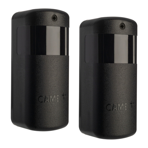
DXR20CAP - Coppia di fotocellule a raggio infrarosso sincronizzato orientabili da esterno a
12 - 24 V AC - DC. Portata: 20 m.
806TF-0040
DXR20CAM - Coppia di fotocellule in alluminio a raggio infrarosso sincronizzato orientabili
da esterno a 12 - 24 V AC - DC. Portata: 20 m.
806TF-0050
Cover in lega di alluminio per fotocellule serie DXR.
Descrizione delle parti A
1Contenitore della scheda
2Scheda elettronica
3Supporto rotante
4Fissaggio supporto rotante
5Viti di fissaggio supporto rotante
6Copertura frontale
7Vite di fissaggio
8Coperchio antivandalico (806TF-0050)
Dimensioni B
Descrizione componenti della scheda C
①Jumper per impostare la portata di
trasmissione (default 20 m)
②DIP per impostare gli indirizzi
③LED segnalazione funzionamento su TX
④Morsetto SY, da utilizzare in caso di 3 o
più coppie di fotocellule (max 8 coppie)
⑤LED segnalazione allineamento RX-TX
⑥LED segnalazione uscita attiva su RX
⑦Jumper per impostare il tipo di contatto
in uscita su RX (default contatto NC)

10 - FA01650M4A - 10/2022 - © CAME S.p.A. -
Dati tecnici
MODELLI DXR20CAP DXR20CAM
Alimentazione (V - 50/60 Hz) 12 - 24 AC - DC 12 - 24 AC - DC
Temperatura d’esercizio (°C) -20 ÷ +55 -20 ÷ +55
Grado di protezione (IP) 54 54
Temperatura di stoccaggio (°C)** -25 ÷ +70 -25 ÷ +70
Classe di isolamento III III
Vita media (Cicli)** 100000 100000
(**) Prima dell'installazione, il prodotto va tenuto a temperatura ambiente nel caso di
stoccaggio o trasporto a temperature molto basse o molto alte.
(***) La vita media del prodotto è un dato puramente indicativo e stimato in
considerazione di conformi condizioni di utilizzo, installazione e manutenzione. Essa
è influenzata anche da ulteriori fattori, quali ad esempio condizioni climatiche e
ambientali.
CInstallazione
1Forare il contenitore della scheda e far passare i cavi elettrici. Determinare
l'orientamento della scheda elettronica.
L'ampiezza massima del raggio è 180° orizzontale e 10° verticale
2Bloccare con le viti il fissaggio del supporto rotante e la scheda elettronica.
3Fissare la copertura frontale.
Collegamenti e settaggi
Si raccomanda di utilizzare cavi tipo FROR 2 x 0,5 mm.
ECollegamento di una coppia di fotocellule.
GCollegamento di due coppie di fotocellule.
Settare ciascuna coppia di fotocellule RX-TX con il proprio indirizo tramite DIP
(1-2-3).
H I Collegamento di più coppie di fotocellule (max 8).
Settare ciascuna coppia di fotocellule RX-TX con il proprio indirizo tramite DIP
(1-2-3) e collegare i morsetti SY delle fotocellule TX tra loro.
In una coppia di fotocellule è obbligatorio impostare tutti i DIP in OFF, come
riportato in RX1 e TX1.

11 - FA01650M4A - 10/2022 - © CAME S.p.A. -
FSe dal quadro comando CAME viene impostata la funzione di test servizi, collegare le
fotocellule TX sui morsetti 10 e TS anzichè 10 e 11 sul quadro comando.
Per i contatti in uscita OUT, verificare sempre le indicazioni relative al collegamento e
alle funzioni nel manuale del quadro comando CAME associato.
In caso di installazione con altre fotocellule di tipo diverso, è consigliato
installare i trasmettitori TX e i ricevitori RX in senso alternato, come in figura F
LED di segnalazione stato
LED Allineamento fotocellule RX-TX
1 lampeggio al secondo debole
2 lampeggi al secondo suciente
3 lampeggi al secondo buono
Acceso fisso ottimo
③Segnalazione di funzionamento su TX
Coppie di fotocellule Lampeggio lento Lampeggio veloce
1 coppia sincronizzata TX1 -
2 o più coppie
sincronizzate TX1 da TX2 a TX8
⑥Segnalazione uscita attiva su RX
LED Segnalazione
Acceso Uscita a riposo
Spento Uscita attiva

12 - FA01650M4A - 10/2022 - © CAME S.p.A. -
ENGLISH
General precautions for installers
Read the instructions carefully before beginning the installation and carry out the
procedures as specified by the manufacturer. • Installation, programming, commissioning
and maintenance must only be carried out by qualified, expert technicians and in full
compliance with the applicable law. • Before carrying out any cleaning or maintenance,
or replacing any parts, disconnect the device from the power supply. • Only use this
product for its intended purpose. Any other use is hazardous. • The manufacturer cannot
be held liable for any damage caused by improper, unreasonable or erroneous use. • The
product, in its original packaging supplied by the manufacturer, must only be transported
in a closed environment (railway carriage, containers, closed vehicles). • If the product
malfunctions, stop using it and contact customer services at https://www.came.com/
global/en/contact-us or via the telephone number on the website.
The manufacture date is provided in the production batch printed on the
product label. If necessary, contact us at https://www.came.com/global/en/
contact-us.
The general conditions of sale are given in the ocial CAME price lists.
Legislative references
The manufacturer CAME S.p.A. declares that the product described in this manual
complies with Directive 2014/53/EU.
The full EU declaration of conformity is available at the following address: www.came.
com.
Dismantling and disposal
Dispose of the packaging and the device responsibly at the end of its life cycle, in
compliance with the laws in force in the country where the product is used. The recyclable
components are marked with the material symbol and ID.
THE DATA AND INFORMATION IN THIS MANUAL MAY BE CHANGED AT ANY TIME AND
WITHOUT NOTICE.
MEASUREMENTS ARE IN MILLIMETRES, UNLESS STATED OTHERWISE.

Description
806TF-0030
DXR20CAP - Pair of synchronised directional infrared photocells for outdoor use 12 - 24 V
AC - DC. Range: 20 m.
806TF-0040
DXR20CAM - Pair of synchronised directional aluminium infrared photocells for outdoor use
12 - 24 V AC - DC. Range: 20 m.
806TF-0050
Aluminium alloy cover for DXR photocells.
Description of parts A
1Control board container
2Control board
3Rotating support
4Rotating support fastening
5Rotating support fastening screws
6Front cover
7Fastening screw
8Vandal-proof cover (806TF-0050)
Size B
Description of control board components C
①Jumper for setting the transmission
range (default: 20 m)
②DIP-switches for setting the addresses
③LED signalling operation on TX
④SY terminal: use where there are 3 or
more pairs of photocells (max. 8 pairs)
⑤LED signalling RX-TX alignment
⑥LED signalling active output on RX
⑦Jumper for setting the type of output
contact on RX (default: NC contact)

14 - FA01650M4A - 10/2022 - © CAME S.p.A. -
Technical data
MODELS DXR20CAP DXR20CAM
Power supply (V - 50/60 Hz) 12 - 24 AC - DC 12 - 24 AC - DC
Operating temperature (°C) -20 ÷ +55 -20 ÷ +55
Protection rating (IP) 54 54
Storage temperature (°C)** -25 ÷ +70 -25 ÷ +70
Insulation class III III
Average life (cycles)** 100000 100000
(**) Before installing the product, keep it at room temperature where it has previously
been stored or transported at a very high or very low temperature.
(***) The average product life is a purely indicative estimate. It applies to compliant
usage, installation and maintenance conditions. It is also influenced by other factors,
such as climatic and environmental conditions.
CInstallation
1Make a hole in the board box and thread the electrical cables through the hole.
Position the control board at the correct angle.
The maximum range is 180° horizontally and 10° vertically.
2Secure in place using the screws for the rotating support and electronic board.
3Attach the front cover.
Connections and settings
Use FROR cables 2 x 0.5 mm.
EConnecting a pair of photocells.
GConnecting two pairs of photocells.
Set each pair of RX-TX photocells with its own address via the DIP-switches
(1-2-3).
H I Connecting multiple pairs of photocells (max. 8).
Set each pair of RX-TX photocells with its own address via the DIP-switches
(1-2-3) and connect the SY terminals on the TX photocells together.
In a pair of photocells, all DIP-switches must be set to OFF, as shown in RX1
and TX1.

15 - FA01650M4A - 10/2022 - © CAME S.p.A. -
FIf the services test function has been set on the CAME control panel, connect the TX
photocells to terminals 10 and TS, instead of 10 and 11, on the control panel.
For the OUT output contacts, always check the connection and function instructions
in the relevant CAME control panel manual.
For installations alongside photocells of a dierent type, we recommend
installing TX transmitters and RX receivers alternately, as shown in the figure F
Status warning LED
LED RX-TX photocell alignment
1 flash per second weak
2 flashes per second sucient
3 flashes per second good
On excellent
③Operation on TX signal
Photocell pairs Slow flash Quick flash
1 synchronised pair TX1 -
2 or more synchronised
pairs TX1 from TX2 to TX8
⑥Active output on RX signal
LED Message
On Output idle
O Output active

16 - FA01650M4A - 10/2022 - © CAME S.p.A. -
FRANÇAIS
Instructions générales pour l’installateur
Lire attentivement les instructions avant de commencer l'installation et d'eectuer les
interventions comme indiqué par le fabricant. • L’installation, la programmation, la mise
en service et l'entretien doivent être eectués par du personnel qualifié et dans le plein
respect des normes en vigueur. • Avant toute opération de nettoyage, d'entretien ou
de remplacement de pièces détachées, mettre le dispositif hors tension. • Ce produit
ne devra être destiné qu'à l'utilisation pour laquelle il a été expressément conçu et
toute autre utilisation est à considérer comme dangereuse. • Le fabricant décline toute
responsabilité en cas d’éventuels dommages provoqués par des utilisations impropres,
incorrectes et déraisonnables. • Le produit, dans l'emballage d'origine du fabricant, ne
peut être transporté qu'à l'intérieur (wagons de chemin de fer, conteneurs, véhicules
fermés). • En cas de dysfonctionnement du produit, cesser de l'utiliser et contacter le
centre SAV à l'adresse https://www.came.com/global/en/contact-us ou au numéro de
téléphone indiqué sur le site.
La data de fabrication est indiquée dans le lot de production imprimé sur
l'étiquette du produit. Si nécessaire, nous contacter à l'adresse https://www.came.
com/global/en/contact-us.
Les conditions générales de vente figurent dans les catalogues de prix
ociels Came.
Références Normatives
Le fabricant, CAME S.p.A., déclare que le produit décrit dans ce manuel est conforme à la
Directive 2014/53/UE.
Le texte intégral de la déclaration de conformité UE est disponible sur Internet à l’adresse
suivante: www.came.com.
Mise au rebut et élimination
Ne pas jeter l'emballage et le dispositif dans la nature au terme du cycle de vie de ce
dernier, mais les éliminer selon les normes en vigueur dans le pays où le produit est
utilisé. Le symbole et le sigle du matériau figurent sur les composants recyclables.
LE CONTENU DE CE MANUEL EST SUSCEPTIBLE DE SUBIR DES MODIFICATIONS À TOUT
MOMENT ET SANS AUCUN PRÉAVIS.
LES DIMENSIONS SONT EXPRIMÉES EN MILLIMÈTRES, SAUF INDICATION CONTRAIRE.

Description
806TF-0030
DXR20CAP - Paire de photocellules à rayon infrarouge synchronisé orientables d’extérieur
12 - 24 VAC – DC. Portée: 20 m.
806TF-0040
DXR20CAM - Paire de photocellules en aluminium à rayon infrarouge synchronisé
orientables d’extérieur 12 - 24 VAC – DC. Portée: 20 m.
806TF-0050
Couvercle en alliage d’aluminium pour photocellules série DXR.
Description des parties A
1Boîtier de la carte
2Carte électronique
3Support pivotant
4Fixation du support pivotant
5Vis de fixation du support pivotant
6Couvercle frontal
7Vis de fixation
8Couvercle anti-vandalisme (806TF-
0050)
Dimensions B
Description des composants de la carte C
①Cavalier de configuration de la portée de
transmission (par défaut 20 m)
②DIP de configuration des adresses
③Voyant de signalisation fonctionnement
sur TX
④Borne SY à utiliser en cas de 3 paires ou
plus de photocellules (max. 8 paires)
⑤Voyant signalisation alignement RX-TX
⑥Voyant de signalisation sortie activée
su RX
⑦Cavalier de configuration du type de
contact en sortie sur RX (par défaut contact
NF)

18 - FA01650M4A - 10/2022 - © CAME S.p.A. -
Données techniques
MODÈLES DXR20CAP DXR20CAM
Alimentation (V - 50/60 Hz) 12 - 24 AC - DC 12 - 24 AC - DC
Température de fonctionnement (°C) -20 ÷ +55 -20 ÷ +55
Degré de protection (IP) 54 54
Température de stockage (°C)** -25 ÷ +70 -25 ÷ +70
Classe d'isolation III III
Durée de vie moyenne (Cycles)** 100000 100000
(**) Avant l'installation, le produit doit être maintenu à température ambiante en cas de
stockage ou de transport à des températures très basses ou très élevées.
(***) La durée de vie moyenne du produit est purement indicative et estimée en tenant
compte des conditions conformes d'utilisation, d'installation et d'entretien. Elle est
également influencée par d'autres facteurs tels que les conditions climatiques et
environnementales.
CInstallation
1Percer le boîtier de la carte et y faire passer les câbles électriques. Déterminer
l'orientation de la carte électronique.
La largeur maximale du rayon est de 180° à l'horizontale et de 10° à la
verticale
2Fixer à l'aide des vis le support pivotant et la carte électronique.
3Fixer le couvercle frontal.
Connexions et configurations
Il convient d'utiliser des câbles FROR 2 x 0,5 mm.
EBranchement d’une paire de photocellules.
GBranchement de deux paires de photocellules.
Configurer chaque paire de photocellules RX-TX avec sa propre adresse par
DIP (1-2-3).
H I Connexion de plusieurs paires de photocellules (max. 8 paires).
Configurer chaque paire de photocellules RX-TX avec sa propre adresse par
DIP (1-2-3) et connecter les bornes SY des photocellules TX entre elles.
Dans une paire de photocellules, tous les commutateurs DIP doivent être
réglés sur OFF, comme indiqué dans RX1 et TX1.

19 - FA01650M4A - 10/2022 - © CAME S.p.A. -
FEn cas de configuration, sur l'armoire de commande CAME, de la fonction de test
services, connecter les photocellules TX sur les bornes 10 et TS au lieu de 10 et 11 sur
l'armoire de commande.
Pour les contacts de sortie OUT, toujours contrôler les indications sur la connexion et
les fonctions dans le manuel de l'armoire de commande CAME associée.
En cas d'installation avec d'autres types de photocellules, il est conseillé
d'installer les émetteurs TX et les récepteurs RX en les alternant comme sur la
figure F
Voyant de signalisation d'état
Voyant LED Alignement des photocellules RX-TX
1 clignotement par seconde faible
2 clignotements par seconde susant
3 clignotements par seconde bon
Allumée en permanence excellent
③Signalisation de fonctionnement sur TX
Paire de photocellules Clignotement lent Clignotement rapide
1 paire synchronisée TX1 -
2 paires synchronisées
ou plus TX1 de TX2 à TX8
⑥Signalisation sortie activée sur RX
Voyant LED Signalisation
Allumé Sortie au repos
Éteint Sortie activée

20 - FA01650M4A - 10/2022 - © CAME S.p.A. -
РУССКИЙ
Общие предупреждения для монтажника
Внимательно прочитайте инструкции, прежде чем приступить к установке
и выполнению работ, согласно указаниям фирмы-изготовителя. • Монтаж,
программирование, ввод в эксплуатацию и техническое обслуживание должны
выполняться квалифицированным и опытным персоналом в полном соответствии
с требованиями действующих норм безопасности. • Перед выполнением работ по
очистке, техническому обслуживанию или замене деталей обесточьте устройство. •
Это изделие должно использоваться исключительно по назначению. Использование
не по назначению считается опасным. • Производитель не несет ответственности
за ущерб в результате неправильного, ошибочного или небрежного использования
изделия. • Изделие в оригинальной упаковке компании-производителя может
транспортироваться только в закрытом виде (в железнодорожных вагонах,
контейнерах, закрытом автотранспорте). • В случае обнаружения неисправности
изделия необходимо прекратить его эксплуатацию и связаться с сервисной службой
по адресу https://www.came.com/global/en/contact-us или позвонить по номеру,
указанному на сайте.
Дата изготовления указана в партии продукции, напечатанной на
этикетке изделия. При необходимости свяжитесь с нами по адресу https://
www.came.com/global/en/contact-us.
С общими условиями продажи можно ознакомиться в официальных
прейскурантах Came.
Нормы и стандарты
Компания-производитель CAME S.p.A. заявляет, что описанное в этом руководстве
изделие соответствует требованиям директивы 2014/53/EU.
Полный текст декларации ЕС о соответствии доступен по адресу: www.came.com.
Утилизация
Не выбрасывайте упаковку и устройство совместно с бытовыми отходами.
Утилизируйте их в соответствии с требованиями законодательства, действующего
в стране установки изделия. Пригодные для повторного использования компоненты
отмечены специальным символом с обозначением материала.
СОДЕРЖАНИЕ ЭТОГО РУКОВОДСТВА МОЖЕТ БЫТЬ ИЗМЕНЕНО В ЛЮБОЕ ВРЕМЯ БЕЗ
ПРЕДВАРИТЕЛЬНОГО УВЕДОМЛЕНИЯ.
ВСЕ РАЗМЕРЫ ПРИВЕДЕНЫ В МИЛЛИМЕТРАХ, ЕСЛИ НЕ УКАЗАНО ИНОЕ.
This manual suits for next models
4
Table of contents
Languages:
Other CAME Security Sensor manuals