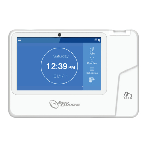
CS TIMECLOCK 3110 Instruction manual

CS TIMECLOCK
3110
QUICK START MANUAL

2
TABLE OF CONTENTS
Time Clock Connectors 3
Installation Instructions 5
1. Hardware Installation 5
2. Network Setup 6
2.1. Setting the IP Address 6
2.2. Setting the NetMask 6
2.3. Setting the Gateway Address 7
2.4. Setting the DNS Address 7
2.5. Enable / Disable DHCP 7
3. Setting the Time, Date and Time Zone 8
3.1. Setting the time from the Internet 8
3.2. Setting the Time manually 8
3.3. Setting the Date manually 9
3.4. Setting the Time Zone 9
4. Enrolling Employees 9
4.1. Adding an Employee 10
4.2. Adding a Card Number 10
Appendix A: Time Zone Codes 11

3
CLOCK INSTALLATION
TIME CLOCK CONNECTORS
The connectors are located at the bottom of the clock
The connectors are described below from left to right with the clock display
and keypad facing upwards
o1 –Siren Trigger
o2 –5-12 Volt Power Input Connector
o3 –RS485 Extender reader connection
o4 –Ethernet RJ45 Connector
o5 –5Volt Power Supply input (not used)
o6 –USB Port no 1
o7 –USB Port no 2

4
The TimeClock provides a trigger connector for to a siren interface and is
indicated as no 1 under the TimeClock Connector’s section.
The Siren Relay Trigger Connector pin connectors are shown and described
below:
oPin 1 and 2 –Normally closed connection
oPin 2 and 3 –Normally Open Connection
oThe trigger connector is rated for 12 Volt

5
INSTALLATION INSTRUCTIONS
1. HARDWARE INSTALLATION
Installation on a upright surface via two key holes at the back of the
TimeClock casing
The keyholes are 86mm apart and 23mm from the top of the TimeClock
casing as shown in the diagram below:
Connect the 5-12Volt power supply (supplied) to the TimeClock’s 5-12 Volt
connecter as indicated in the connector layout diagram as connector no 2.
The supplier power supply must be connected to the power main via a
normal kettle or PC type connector lead (not supplied)
Connect the network fly lead cable to the TimeClock’s RJ 45 connector
(connector no 4 in the layout diagram)

6
2. NETWORK SETUP
Press 900# to view the clock menu
Press 8 to select “Network”
To cancel at any time press *
2.1. SETTING THE IP ADDRESS
Press 1 (“Set IP”). “Swipe Admin Card or Finger” is displayed on screen
Enter 9970#. “Admin Demo User” is displayed for about 2 seconds
followed by “Enter IP Address”
Where you are entering an IP address, the key sequence for address
192.168.0.111 will be:
o192168000111
The clock will then confirm the address and save it
2.2. SETTING THE NETMASK
Enter the “Network” menu as in 2.
Press 2 (“NetMask”). “Swipe Admin Card or Finger” is displayed on
screen
Enter 9970#. “Admin Demo User” is displayed for about 2 seconds
followed by “Enter NetMask”
Enter the gateway address as described in 2.1. The clock will then
confirm the address and save it

7
2.3. SETTING THE GATEWAY ADDRESS
Enter the “Network” menu as in 2.
Press 3 (“Gateway”). “Swipe Admin Card or Finger” is displayed on
screen
Enter 9970#. “Admin Demo User” is displayed for about 2 seconds
followed by “Enter Gateway”
Enter the gateway address as described in 2.1. The clock will then
confirm the address and save it
2.4. SETTING THE DNS ADDRESS
Enter the “Network” menu as in 2.
Four DNS addresses can be entered
Press 4 (“DNS 1”) to enter the first address. “Swipe Admin Card or
Finger” is displayed on screen
Enter 9970#. “Admin Demo User” is displayed for about 2 seconds
followed by “Enter DNS 1”
Enter the DNS address as described in 2.1. The clock will then confirm
the address and save it
Repeat the process for DNS 2, DNS 3 and DNS 4 if required
2.5. ENABLE / DISABLE DHCP
Enter the “Network” menu as in 2.
Press 8 (“DHCP”). “Swipe Admin Card or Finger” is displayed on screen
Enter 9970#. “Admin Demo User” is displayed for about 2 seconds, then
“Turning DHCP On / Off. Rebooting…”, followed by “Clock Inactive”
The time and date will be displayed when the reboot is complete
8
3. SETTING THE TIME, DATE AND TIME ZONE
Press 900# to view the clock menu
Press 4 to select “Time”
To cancel at any time press *
3.1. SETTING THE TIME FROM THE INTERNET
Press 1 (“ Int Time”). “Swipe Admin Card or Finger” is displayed on
screen
Enter 9970#. “Admin Demo User” is displayed for about 2 seconds
followed by “Updating Time…”
3.2. SETTING THE TIME MANUALLY
Enter the “Time” menu as in 3.
Press 2 (“Set Time”). “Swipe Admin Card or Finger” is displayed on
screen
Enter 9970#. “Admin Demo User” is displayed for about 2 seconds
followed by “TIME hh mm ss”and the current time below that
Where you are entering the time, the key sequence for 09:21:13 will be:
o09#
o21#
o13#
“Setting the time” will be displayed

9
3.3. SETTING THE DATE MANUALLY
Enter the “Time” menu as in 3.
Press 3 (“Set Date”). “Swipe Admin Card or Finger” is displayed on
screen
Enter 9970#. “Admin Demo User” is displayed for about 2 seconds
followed by “DATE dd mm yyyy” and the current date below that
Where you are entering the time, the key sequence for 01 June 2008 will
be:
o01#
o06#
o2008#
“Setting Date” will be displayed
3.4. SETTING THE TIME ZONE
Enter the “Time” menu as in 3.
Press 4 (“Set TimeZone”). “Swipe Admin Card or Finger” is displayed on
screen
Enter 9970#. “Admin Demo User” is displayed for about 2 seconds
followed by “Enter New TimeZone”
Enter your Time zone code followed by #. The TimeZone codes are
listed under Appendix A
“Setting New TimeZone” will be displayed and the clock will reboot
4. ENROLLING EMPLOYEES
Press 900# to view the clock menu
Press 2 to select “Enroll”
To cancel at any time press *

10
4.1. ADDING AN EMPLOYEE
Press 1 (“Add Emp”). “Swipe Supervisor Card or Finger” is displayed on
screen
Enter 9970#. “Supervisor Demo User” is displayed for about 2 seconds
followed by “Enter New Employee Number”
Enter the employee number followed by #
“Employee Added”, “Employee XXXX” will be displayed, where XXXX is
the employee number entered
4.2. ADDING A CARD NUMBER
Enter the “Enroll” menu as in 4.
Press 2 (“Add Card”). “Swipe Supervisor Card or Finger” is displayed on
screen
Enter 9970#. “Supervisor Demo User” is displayed for about 2 seconds
followed by “Enter New Card for Employee XXXX”
Enter the card number followed by a #
“Card Added for Employee XXXX” will be displayed, where XXXX is the
employee number entered

11
APPENDIX A: TIME ZONE CODES
1: GMT+1
2: GMT+2
3: GMT+3
4: GMT+4
5: GMT+5
6: GMT+6
7: GMT+7
8: GMT+8
9: GMT+9
10: GMT+10
11: GMT+11
12: GMT+12
21: GMT-1
22: GMT-2
23: GMT-3
24: GMT-4
25: GMT-5
26: GMT-6
27: GMT-7
28: GMT-8
29: GMT-9
30: GMT-10
31: GMT-11
32: GMT-12
40: GMT+0
1000: Africa/Johannesburg
2000: Australia/ACT
2001: Australia/North
2002: Australia/NSW
2003: Australia/Queensland
2004: Australia/South
2005: Australia/Tasmania
2006: Australia/North
2007: Australia/Victoria
2008: Australia/West
3000: Europe/Amsterdam
3001: Europe/Berlin
3002: Europe/London
3003: Europe/Madrid
3004: Europe/Oslo
3005: Europe/Paris
3006: Europe/Rome
3007: Europe/Auckland
4000: Pacific/Auckland
5000: US/Alaska
5001: US/Central
5002: US/Eastern
5003: US/Hawaii
5004: US/Mountain
5005: US/Pacific
Table of contents
Other CS TIMECLOCK Time Clock manuals