CSC RX1E User manual

. 1 .
Preface
The electric motorcycle can be used on road only and by one driver.
The user should read the user’s manual carefully prior to using the product. The user shall have a proper command of
basic operation functions, usage method and other common sense for the model. The data, technical specifications and
performance parameters labeled in the manual are compiled based on the latest status. The company reserves the right to
amend the manual at any time without a separate notice and does not assume any liabilities. Please understand this. No
entities or individuals shall be allowed to reproduce any part of the manual without the company’s written approval. We
sincerely wish that you can tell us your opinions on the design, manufacture or quality of the product. If you have any positive
recommendations and opinions, please inform us by letter for timely improvement.
There is no description of repairing in this manual. For repairing, the users can refer to Component Catalogue and Service
Manual for a better understanding of the name of the components, installation structure, faults, service method and others.
For more information, please contact the dealers or the service station. The company will provide you with the best and fastest
services.
Please dispose of the used battery responsibly to protect the environment. Please check with your local government for
disposal guidelines.
The contents and images of this manual are for reference only. Specifications are subject to the physical product.
Please purchase the original genuine parts and accessories manufactured by our company.

Symbolic Meaning of Safety Information in the User’s Manual
It indicates there is potential high hazard. Failure to follow the instructions will lead to personal injury or death.
It indicates there is potential moderate hazard. Improper operation may cause harm to personal and property safety.
It indicates a potential danger that may cause damages to the motorcycle if any misoperation.
The most efficient service information is available for faster warranty service and more understandable instructions.
Security Information
In order to ensure the safety of users and others, please operate strictly in accordance with the safety information
and driving steps provided in the operation manual. The safety information reminds users to pay attention to potential
hazards and avoid endangering yourself and others.
This manual contains important safety information that could help prevent injury or death. Please read it carefully.
CSC Motorcycles
Address: 1331 W Foothill Blvd, Azusa, CA
Customer service hotline: 1-800-884-4173
For details, please click the website of our company: www.cscmotorcycles.com.
. 2 .
Security
Informa

Preface
Table of Contents
Security Information
Matters Needing Attention
Vehicle Identification Number (VIN) and Engine Number
Motorcycle Introduction
Electric Switch
USB, Charging Port
Instrument Indicator
Left handle switch
Right handle switch
Control part
Load limit
Inspection before driving
Starting and Driving Operation
Inspection and Adjustment after the Running-in Period
Safe Driving Guidance
Periodic Maintenance Schedule
Maintenance Requirements
Use and Maintenance of Charger
Use and Maintenance of Battery
Maintenance of Drive Motor
Inspection and Adjustment of Brakes
Cleaning and Storage
Common Fault Diagnosis and Troubleshooting Methods
Technical Specifications and Performance Parameters
Electrical Schematic Diagram . 3 .
Table of Contents

. 4 .
Instruction to User
1. We recommend wearing a helmet, eye protection, gloves and
other protective equipment while driving.
2. Do not hang anything on the steering wheel, as this could
interfere with safe driving.
3. To prevent battery damage, please use only the original
charger that was provided with your motorcycle by our
company.
4. It is forbidden to wear loose clothes, slippers, etc., otherwise
the clothing is easy to hook on the handle and accessories,
resulting in potential safety hazards.
5. Before unplugging the power plug, please turn off the air switch
and switch lock first.
1. After unpacking, please check the attached accessories and
various materials according to the packing list.
2. This model is a single-rider vehicle. The maximum payload for
the electric vehicle is 330 pounds, and the maximum payload for
the trunk is 6.6 pounds.
3. It is forbidden to refit any part of the electric vehicle, otherwise it
will affect the reliability, stability and comfort of the electric
vehicle.
4. To prevent battery damage, please fully charge the battery each
time. Do not turn the battery upside down while charging. Do not
wash the electric vehicle with high-pressure water, as this could
damage the internal electronic components and circuits.
1. This operation manual is an essential part of the electric vehicle.
It must be attached to the vehicle when it is transferred to
another person for use.
2. To prevent battery degradation due to prolonged discharge,
charge your electric motorcycle at least once a month even if you
are not using it.
3. During the running-in period or warranty period, the user shall
regularly go to the dealer or the company's maintenance service
station for regular maintenance and adjustment.
1. Strictly abide by traffic regulations and drive safely.
2. Users who don't have motor vehicle driver’s license should not
drive electric vehicles.
3. It is not allowed to lend electric vehicles to the one without driving
license.
4. In order to ensure driving safety, it is forbidden to drive after
drinking and taking drugs.
5. This vehicle is not intended for use in motorcycle racing. Any
mechanical failures or personal injuries resulting from its use in
such events are the sole responsibility of the user.
6. People with mental illness, history of mental illness, heart
disease, deaf-mutes and the disabled are prohibited from driving
electric vehicles.
! Caution
! Warning ! Suggestion
Please read this manual carefully before using the electric vehicle!
! Danger
. 5 .
23
1
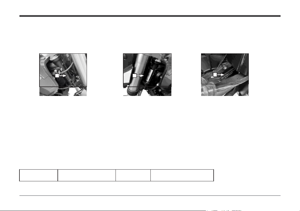
Vehicle Identification Number (VIN) and Engine Number
Vehicle identification number (VIN), engine number and vehicle certificate are used to apply for driving license and motorcycle
account.
1.The vehicle identification
number (VIN) is printed on the
right frame riser.
Please fill in the corresponding number for future inquiry:
2. The vehicle nameplate is
riveted on the left frame riser. 3. The motor number is engraved
on the right housing of the motor.
Frame VIN Code
Motor
Number
Instruction to User
. 6 .
Instruction to User
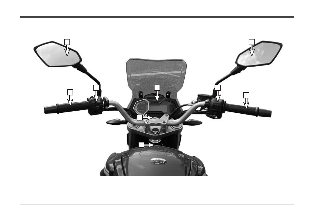
1. Rear view mirror 2. Left steering handle 3. Left control switch 4. Instrument assembly
5. Right control switch 6. Throttle 7. Ignition lock 8. Storage box lock
1 1
236
4 5
7
8
Motorcycle Introduction
Motorcycle
Introduction
Handlebars
Motorcycle Introduction
1
2
6
7
8
910
4
5
3
Instruction to User
. 7 .
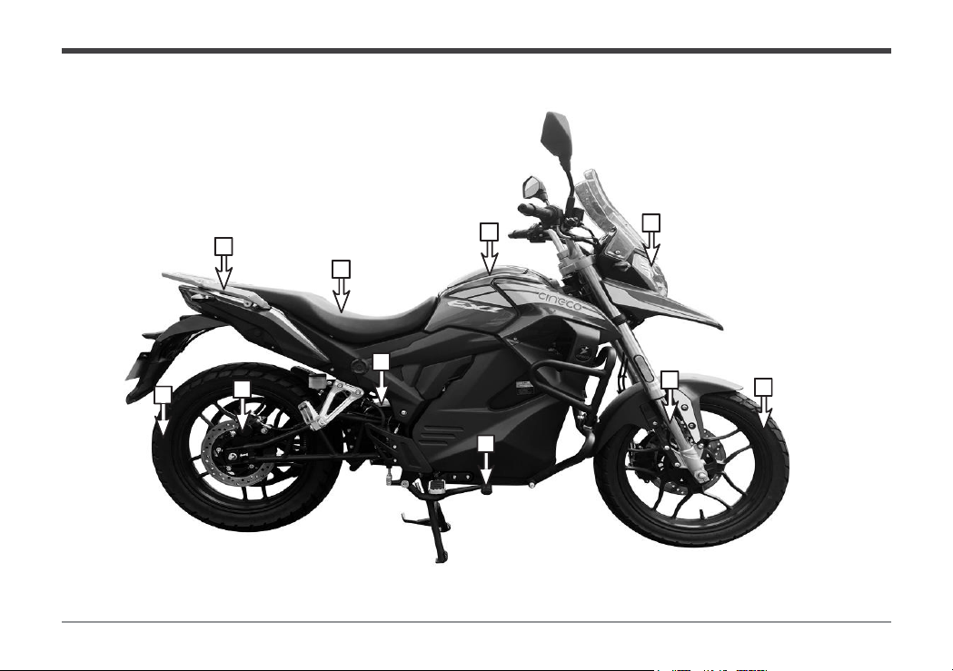
1. Rear armrest 2. Seat cushion 3. Storage box 4. Headlight 5. Rear wheel
6. Rear disc brake 7. Motor 8. Rear brake pedal 9. Front shock absorber 10. Front wheel

4
5
8
27
1
910
6
Instruction to User
3
. 8.
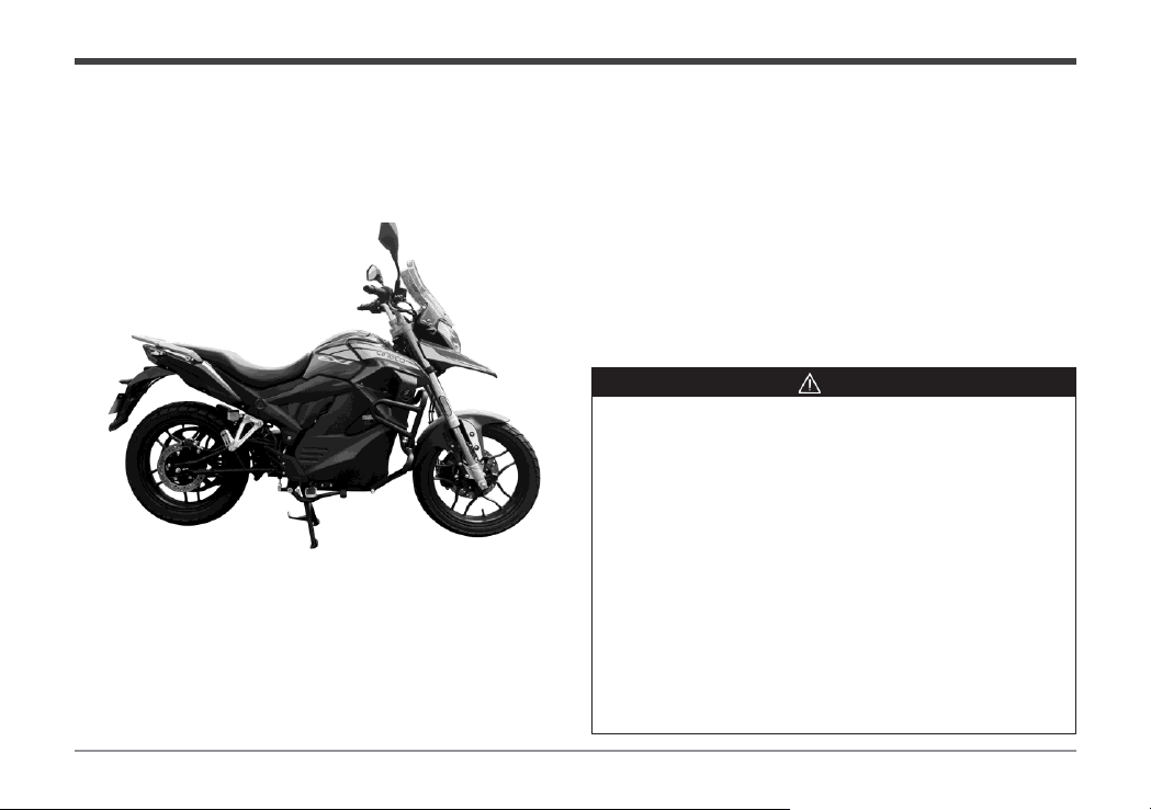
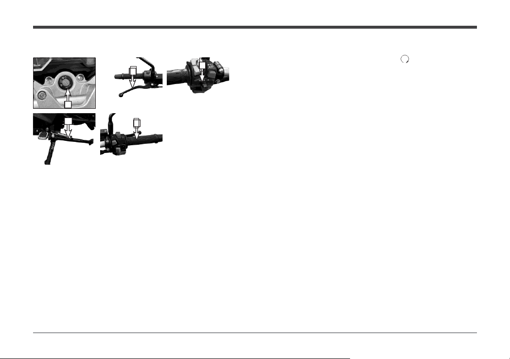
Motorcycle Introduction
1. Front wheel 2. Front brake 3. Engine guard 4. Charging interface
5. Kickstand 6. Center stand 7. Drive belt 8. Taillight 9. Drive pulley 10. Rear
wheel
Introduction
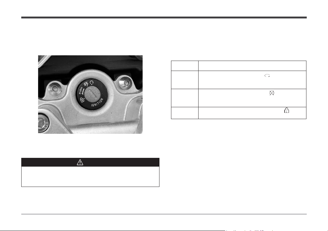
Name Functional Description
1. How to
turn on
the switch
Turn the key to the
position “ ” and turn on
the circuit to start the motor.
2. How to
turn off
the switch
Turn the key to
the position “ ”. Do not
start the vehicle when the circuit is
disconnected
.
3. Steering
lock
Press down and rotate to the position“ ” to
lock the
steering.
. 9 .
Warning
Park the motorcycle in a safe place and use the steering lock to avoid
theft.
Instruction to User
Electric Switch
Electric
1
2
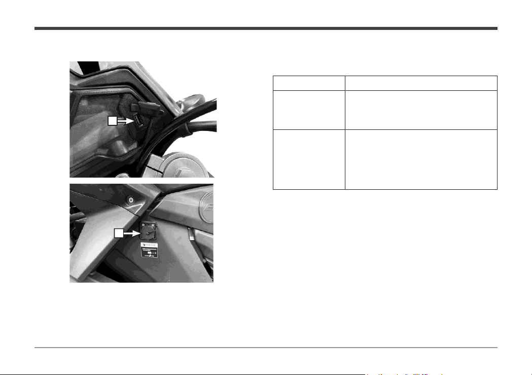
Vehicle Modification Instructions
Do not connect devices that use more than 20W of power to the USB port. We do not recommend modifying
the vehicle. You will lose your warranty and we will not be liable for any problems caused by the changes.
Instruction to User
Name Direction for Use
1.USB port
The USB interface is located on the
right side of the instrument panel and
connected to the mobile phone charging
line for mobile phone charging.
2. Charging
interface
The charging port for the motorcycle
battery is located on the left side of the
motorcycle, under the body panel that
covers the battery. To charge the battery,
connect the charging cable to the port.
. 10 .
USB, Charging Port
. 11 .
Instruction to User
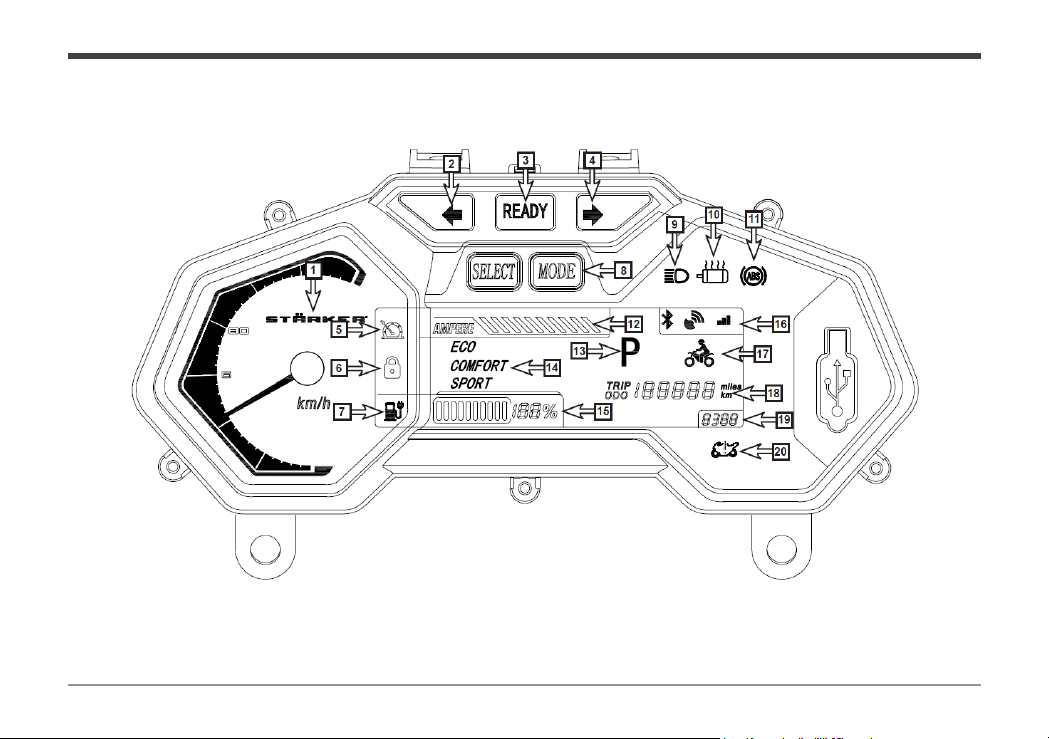
Instrument Indicator
Instrument
. 12
.
Instruction to User
Name Functional Description
11. ABS fault light
When starting, the ABS fault light is on and it will be
off if the speed is above 20km / h.
12. Ammeter
The actual bus current of the controller is
18A per
grid.
13. P mode lamp
Whenthe indicator light ison, the vehiclecannot be
started. Press
the Pmode key of the handle switch to
release it before starting the vehicle.
14
. Riding
mode display
Display the driving mode of the vehicle, including
ECO, COMFORT, SPORT
15. Power display
It is used to display the current battery capacity of
the electric vehicle.
16. Bluetooth
signal
GPS
signal GPRS
signal
The indicator light is on when the vehicle is
connected with a Bluetooth signal.
GPS
positioning system signal display. GPRS mobile app
system signal display
17. Riding status
When the vehicle speed is ≥ 1, this sign is
displayed
18. Odometer
TRIP is the display of subtotal mileage, and the
subtotal mileage can be cleared.
ODO is the
accumulated mileage generated by the vehicle
during driving.
19. Fault display
It will display the fault code and fault code
information. If it is displayed, please visit
the
company's special maintenance service center for
troubleshooting.
20. Fault indicator
Prompt for faults of motor, controller, beam steering
handle, battery, etc
.
Name Functional Description
1. Speedometer
Displays the running speed of the vehicle.
2. Left turn
indicator
When the left turn indicator is on, “
” light
flashes.
4. Ready light
READY
After the electric vehicle is powered on, the
Ready light will be on when there is no fault
in the self
-
test, and it will be off when there is
fault.
10. Right turn
indicator
When the right turn indicator is on,“
” light
flashes.
5. Cruise control
indication
When the indicator light is on, the cruise
control function is on.
6. Vehicle locking
indication
When the indicator light is on, the vehicle is
locked, and do not ride the locked vehicle.
7. Charging
reminder
When the indicator light flashes, it indicates
that the electric quantity is low, please charge
it as soon as possible.
8. LCD setting
key
Press
the MODE key > 2s to reset
TRIP.
P
ress the MODE + SELECT key to
display
the
odometer in Inch or Metric Mode.
9. High beam
indicator
When using the high beam, the high light
indicator “
” is on.
10. Motor over
temperature fault
When the light is on, it indicates the motor
over temperature fault state.
Instrument
Indicator 2
. 13 .
Instruction to User
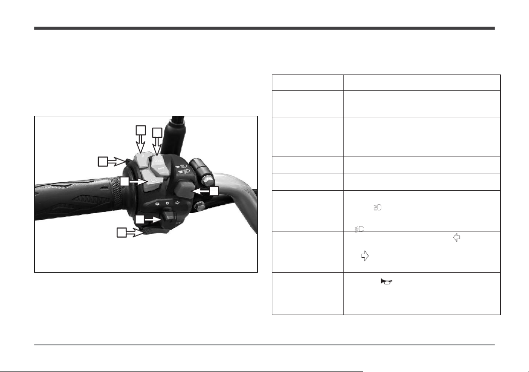
6
7
25
34
Name Direction for Use
1.
Passing light
switch.
To flash your high beams at night when passing
another vehicle, press this “PASS” switch.
2.
Cruise control
button
To activate cruise control, press this button while
driving at a steady speed and do not touch the
throttle. Cruise control will turn off when you
brake.
3. Reverse button
Press the reverse button and then twist the
throttle to make the vehicle go backwards.
4. LCD setting key
The operation method is the same as the
corresponding function key of the instrument.
2. Dimmer switch
When
the lighting switch button is pressed to
the
position“
”, the high beam lamp is turned
on.
When
the lighting switch button is pressed to
the
“
”position, the low beam lamp is turned
on.
4. Turn signal switch
Push the turn signal button to the “ ” position to
signal a left turn. Push the turn signal button to
the “ ” position to signal a right turn.
3. Horn button
Press the “ ” button to sound the horn.
Left handle switch
The main functions of the left handle switch are as follows:
1

. 14 .
Instruction to User
Right handle switch
The main functions of the right handle switch are as follows:
Name
Direction for Use
1.Pmodekey
When the vehicle is parked, the indicator
light on the instrument is on; When the
user presses this key, the indicator light
will be off and the vehicle can be started.
2.Emergency
switch
When the switch is pulled to the
position
“ ”, the left and right turn
signals flash simultaneously.
3.Lighting
switch
Pull the switch to the position, and the
headlamp is on; Pull the switch to "
"
position, the position light is on; Pull the
switch to the position "
", turn off the
electric vehicle lighting system.
4.Speed
control switch
You can change the driving mode as
needed while riding the vehicle. The
dashboard will show you the current
mode.
5.
Throttle
control
Turn the
throttle
control handle to control
the running speed of the electric vehicle.
1
2
34
5
. 15 .
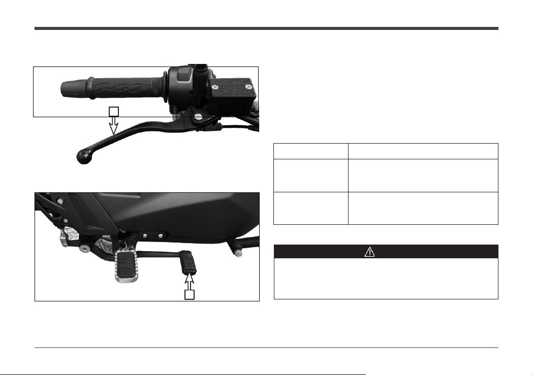
The brakes of this model are equipped with front and
rear disc brakes, and the braking performance is reliable.
Braking is related to personal and property safety and must
be regularly and correctly adjusted and maintained to
achieve the goal of safe driving.
For adjustment and maintenance of braking, it is
recommended to visit our special service center for this
service from time to time.
Suggestion
1
2
Instruction to User
Name Direction for Use
1. Front brake
handle lever
Control the running speed of the front
wheel, and its working stroke is: 10
mm ~20 mm.
2. Rear brake pedal
Control the running speed of the rear
wheel, and its working stroke is: 20
mm ~ 30 mm.
Control part
Controls
. 16 .
34
5
Instruction to User
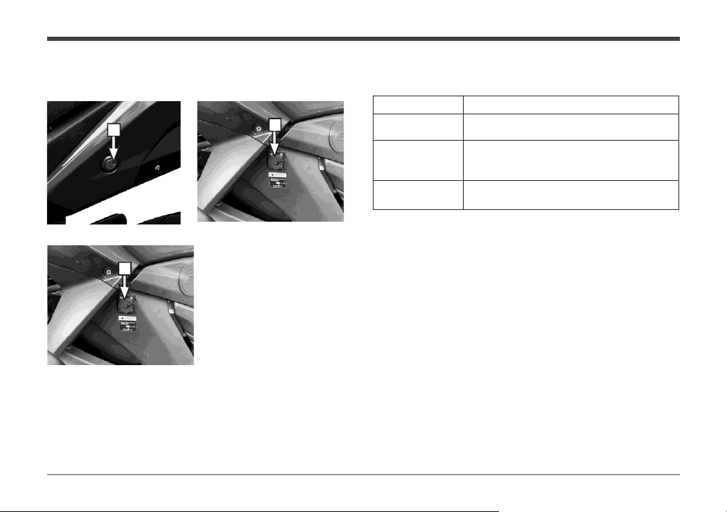
Control part
Name Direction for Use
3
. Seat lock
Insert the key and turn clockwise to open
the seat cushion.
4. Locker lock
Insert the key and turn clockwise to
turn on the locker light under the seat
cushion
.
5. Charging
interface
Connect the charger to charge the battery
Charging
. 17 .
1
This model is made for one rider and one passenger
only. Do not exceed this limit or you could compromise the
safety and stability of the vehicle.
Factory-determined maximum payload of the finished
vehicle : 330 lbs. The maximum load of the locker : 11 lbs.
Danger
1. Follow these instructions carefully. If you overload the
vehicle and cause a crash that injures or kills someone,
you will be responsible for the outcome.
2. The company will not cover any damage to the luggage
rack, such as peeling paint, warping, or chipping
chrome, that results from improper use by the user. The
warranty does not include repair, replacement or refund
for such damage.
3. Please secure your cargo before driving to avoid any
hazards from loose items. For the best stability, place
your cargo near the center of the motorcycle and make
sure it is evenly distributed on both sides.
Instruction to User
Load limit
Load
Limit

. 18 .
Operation Guide
Inspection before driving
Before driving, check in accordance with the following requirements to ensure users' safe driving and successful driving.
NO.
Items
Check
Remark
1
Battery
Check if the battery has enough power.
Depending on how far and how
often you ride your motorcycle, you
should perform three levels of
maintenance regularly:
Level I Maintenance: From 600 to
1,500 miles, focus on lubricating and
tightening the parts.
Level II Maintenance: From 1,500
to 3,700 miles, check, adjust,
lubricate and tighten the parts.
Level III Maintenance: From 3,700
to 6,200 miles, do a thorough
analysis, cleaning, inspection and
adjustment of the parts. Lubricate
and tighten them as well. Replace
any worn
-out parts and fix any
potential problems.
We recommend that you take your
motorcycle to our authorized service
center for installation, tuning and
maintenance.
2
Drive device
Check whether the controller and drive motor are working properly.
3
Brake oil
Check whether the oil is deteriorated and whether the capacity is
lower than the lower scale line.
4
Brake handle
Check whether the
front brake has pressure.
5
Shock absorber
Check whether the
suspension works properly.
6
Throttle
Check
for smooth operation of the throttle.
7
Handlebar
Check
for smooth movement and full turning range of bars.
8
Tire/wheel
Check tire pressure and wear
9
Lighting/signal indicator
Check whether the lighting lamp/signal lamp/indicator lamp is
working.
10
Brake
Check the wear of brake shoes and whether the braking
performance is good.
11
Side stand
Check the
side stand for bending, deformation, and good return.
12
All
-vehicle fasteners
Check whether the fasteners of the finished vehicle are
tightened
securely.
Inspection
Operation Guide
Starting and Driving Operation
1
23
5
1. Turn the switch lock to the position“ ” and turn on the
ignition of the electric vehicle.
2. Hold the front and rear brake levers to prevent the
motorcycle from sliding.
3. Pleaseuse the left blinker to warn pedestrians and carswhen
exiting your spot.
4. Retract the kickstand to unlock the controller’s safety
mode.
5. Release the front and rear brakes, turn the throttle
slightly with your right hand to move the electric
vehicle slowly, and then put your feet on the pedals.
Caution
1. When you park the bike and lower the kickstand, it goes into safety mode where the controller cuts the power and the motor
stops the bike from moving. This stops someone from accidentally turning the handlebars and making the bike take off.
2. The motorcycle takes 2 seconds for the bike to do a self-check, and it’s good to go when the light on the dashboard turns
green.
3.Please wear protective equipment (e.g. helmet, protective gloves, protective glasses, protective clothing, etc.) before driving.
. 19 .
4
and Driving
Table of contents
Other CSC Motorcycle manuals


