CSE BIOMARINE PROIWT User manual


046121 Model PROIWT Communication Interface Revision: C
User Manual
2
Table of Contents
1.0 Cautions and Limitations 3
2.0 MSHA Electrical Approval 4
3.0 Introduction 4
4.0 Installation 5
5.0 Communication System Use 7
6.0 Communication System Post Use 8
7.0 Illustrated Parts List 9

046121 Model PROIWT Communication Interface Revision: C
User Manual
3
1.0 Cautions and Limitations
•Failure to properly use and maintain this product could result in injury or death.
•Never substitute, modify, add, or omit parts. Use only exact replacement parts in the configuration as
specified by Biomarine Inc.
•The ongoing effectiveness and reliability of any protective breathing equipment is dependent upon the
user/owner’s expertise in using and maintaining the equipment.
•The user shall reference and abide by all cautions and limitation provided in the BioPak 240R
respirator manuals.
•The user shall reference and abide by all cautions and limitation provided in the Innovative Wireless
Technologies (IWT) SENTINELTM Wireless Mesh Communication and Tracking System manuals.
•The model PROIWT Communication Interface is suitable for use only with the Biomarine BioPak
240R respirator and associated PRO PP facemask.
•The PROIWT components have not been evaluated for use in applications involving direct open
flame or high radiant heat.
•The PROIWT components have not been evaluated for use in applications that may expose the user
to chemical, biological, radiological, or nuclear agents (CBRN).
•DO NOT attempt to fit the PROIWT Communication Interface to any other manufacture or model of
respirator or facemask other than the BioPak 240R respirator or the PRO PP facemask.
•The user bears full responsibility for properly maintaining this equipment including inspections,
cleaning, maintenance, and care.
•The facemask and installed PROIWT components shall be thoroughly cleaned and disinfected prior
to each use.
•If the respirator is going to be utilized without the services of the PROIWT communication interface it
is strongly suggested to remove the interface components from the facemask and re-install the
original facemask voice emitter front guard.
•The PROIWT Communication Interface may be used with IWT Part Number FAA9100-411 speaker
microphone only.
•The PROIWT Communication Interface has been MSHA approved for intrinsic safety ONLY when
properly interfaced with the following Innovative Wireless Technologies communication systems.
SENTINELTM Wireless Mesh Communication and Tracking System
MSHA Approval No: 23-A120005-0
•HEARING PROTECTION WARNING: This communications product is designed to produce a
specific audio output level at a maximum rated power. Many countries now have regulations defining
the amount of noise that an individual can be subjected to during a normal workday. The duration of
exposure, and the level of ambient noise will affect compliance to these regulations. Compliance is
application dependent, and standards vary. It is the SOLE RESPONSIBILITY of the end user to
determine applicability of and compliance to local hearing protection regulations.

046121 Model PROIWT Communication Interface Revision: C
User Manual
4
2.0 MSHA Electrical Approval
Innovative Wireless Technologies
1100 Main Street, Lynchburg, VA 24504 USA
Model: PROIWT
Permissible Communication Interface
MSHA Approval No: 23-A120005-0
Tested for intrinsic safety in methane-air mixtures only.
Warnings:
MSHA approved for use with one of the following IWT
communication systems only:
SENTINELTM Wireless Mesh Communication and
Tracking System
The interface can only be connected to the Biomarine
Inc. PRO PP facemask.
3.0 Introduction
The PROIWT Communication Interface will provide the user with a method to interface an Innovative
Wireless Technologies intrinsically safe communication system with the NIOSH-approved BioPak 240R
respirator. The system consists of a MSHA-approved interface component that will position a microphone
into the speech outlet of a Biomarine PRO PP facemask.A lapel-mounted speaker will connect to the
mask via either a 12” or 18” coax cable and the speaker will also interface to a two-way radio via a coiled
cable. The radio and remainder of the communication system is supplied directly by Innovative Wireless
Technologies.
Installation of the PROIWT interface to the PRO PP mask will not interfere with the operation of the
standard PRO PP voice emitter. Speech can be heard both through the microphone and through the
mask emitter simultaneously.
Warning: It is strongly recommended to install the PROIWT Interface to the PRO PP mask and
leave it in place at all times. Multiple installations and removals will tend to strip the
screw holes in the mask speech channel body. Should one or more the screw holes
become stripped; a replacement speech channel body can be ordered from Biomarine
under part number B2-06-6002-93-0.

046121 Model PROIWT Communication Interface Revision: C
User Manual
5
4.0 Installation
The PROIWT interface will install into the PRO PP facemask in place the facemask voice emitter front
cover. The speaker portion of the system will clip to the lapel of the user’s shirt or to the harness of the
BioPak 240R respirator. A cable is utilized to connect the facemask interface components to the speaker.
The speaker is provided with a coiled cable attached that will interface with the 2-way radio supplied with
the Innovative Wireless Technologies communication system.
Warning: Do not damage the voice emitter cup of the facemask during PROIWT installation.
The voice emitter, located internal to the mask, cannot be cut, slit, punctured, or
otherwise damaged. A damaged voice emitter will result in a breach of the respirable
air circuit of the BioPak.
1. Using a T20 Torx screwdriver, remove the four front cover screws and reserve for reuse as
depicted below.
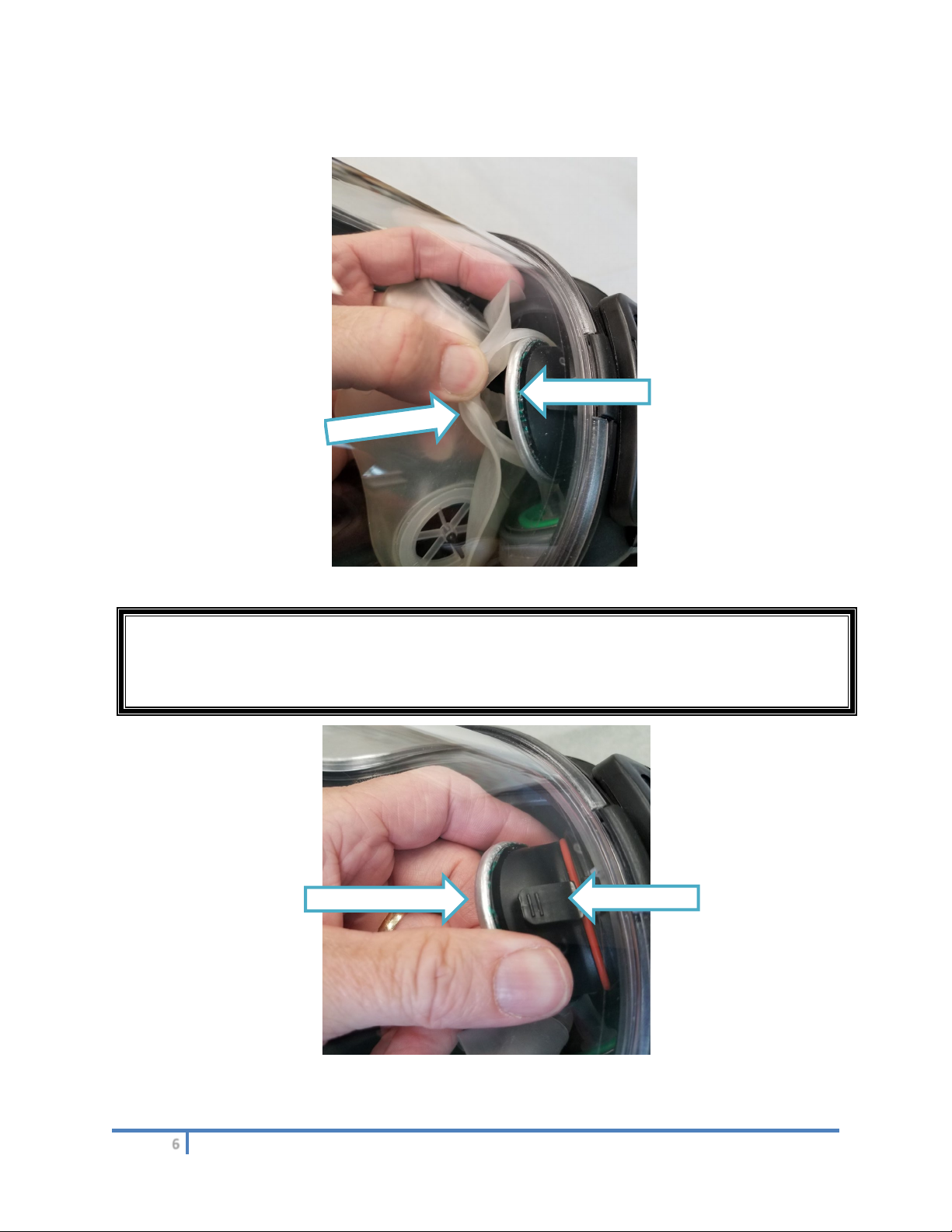
2. Inspect the rubber skirt of the mask and verify that it is properly positioned within the groove of the
speech channel body as depicted below. The skirt must be positioned in the groove of the speech
channel body around its entire perimeter.
046121 Model PROIWT Communication Interface Revision: C
User Manual
6
3. Remove the nose cup from the circumference of the voice emitter. Do not remove the nose cup
from the breathing port.
I
4. Remove the voice emitter by pushing down on the release tab and pulling straight out.
Warning: Do not damage the voice emitter cup of the facemask during PROIWT installation.
The voice emitter, located internal to the mask, cannot be cut, slit, punctured, or
otherwise damaged. A damaged voice emitter will result in a breach of the respirable
air circuit of the BioPak.
Voice Emitter
Nose Cup
Release Tab
Voice Emitter
046121 Model PROIWT Communication Interface Revision: C
User Manual
7
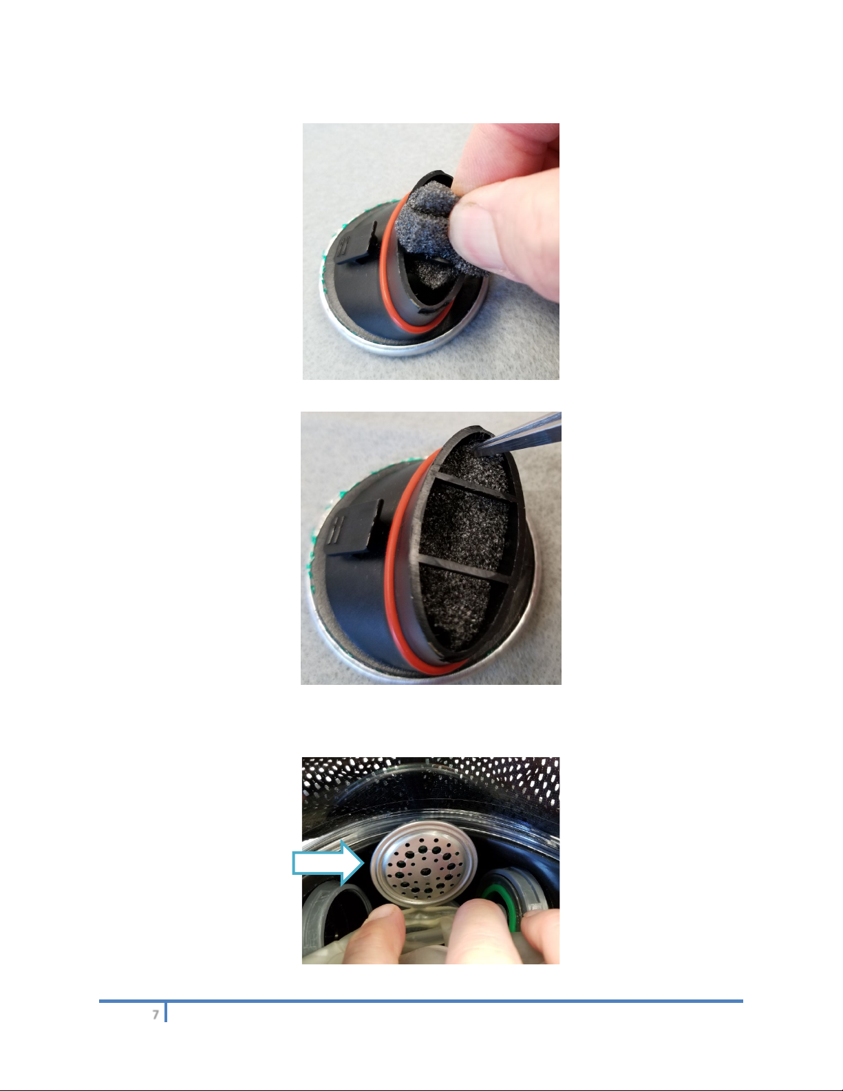
5. Install the trapezoid-shaped foam piece into the open end of the vice emitter as depicted below.
Foam Insertion
Foam Positioning
6. Reinstall the voice emitter into the mask making sure that the release tab fully engages.
046121 Model PROIWT Communication Interface Revision: C
User Manual
8
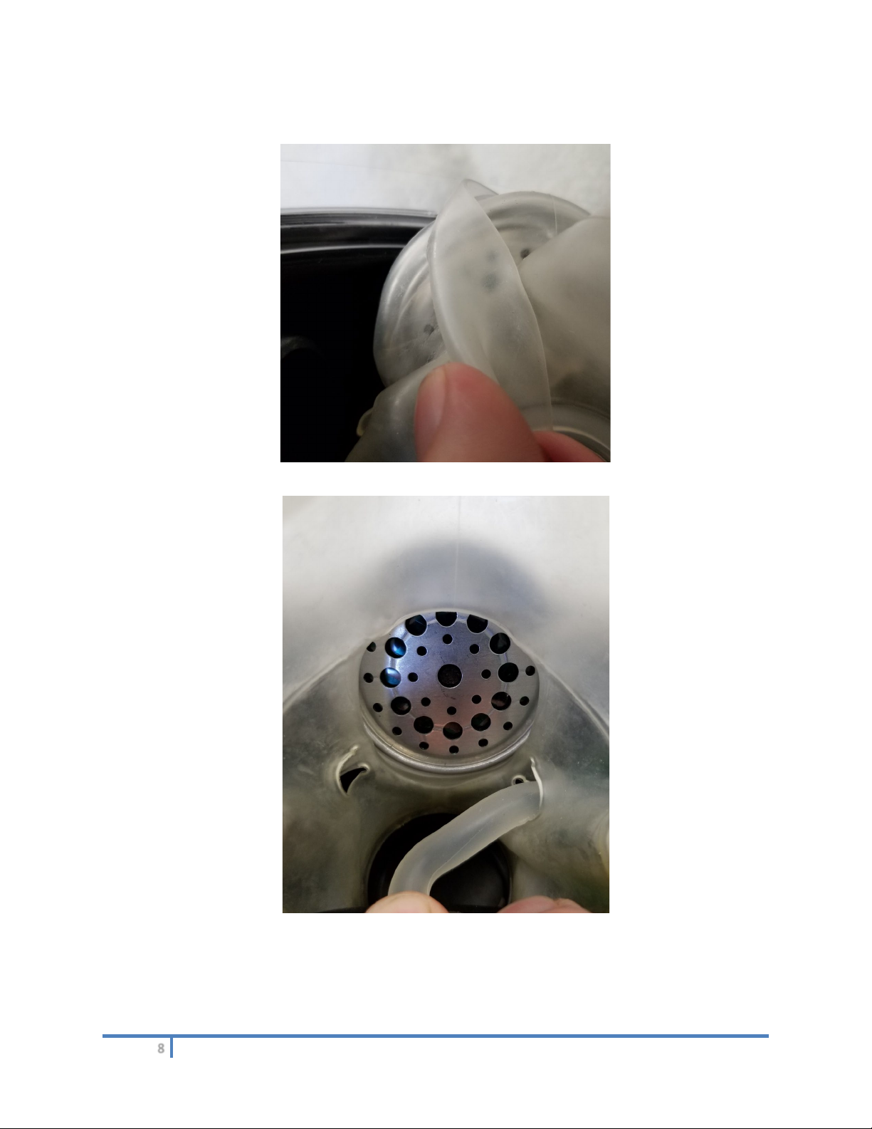
7. Reinstall the nose cup around the perimeter of the voice emitter as depicted below. If the mask is
fitted with a drink tube, make sure the drink tube is properly positioned as depicted.
Nose Cup Installation
Drink Tube Positioning
046121 Model PROIWT Communication Interface Revision: C
User Manual
9
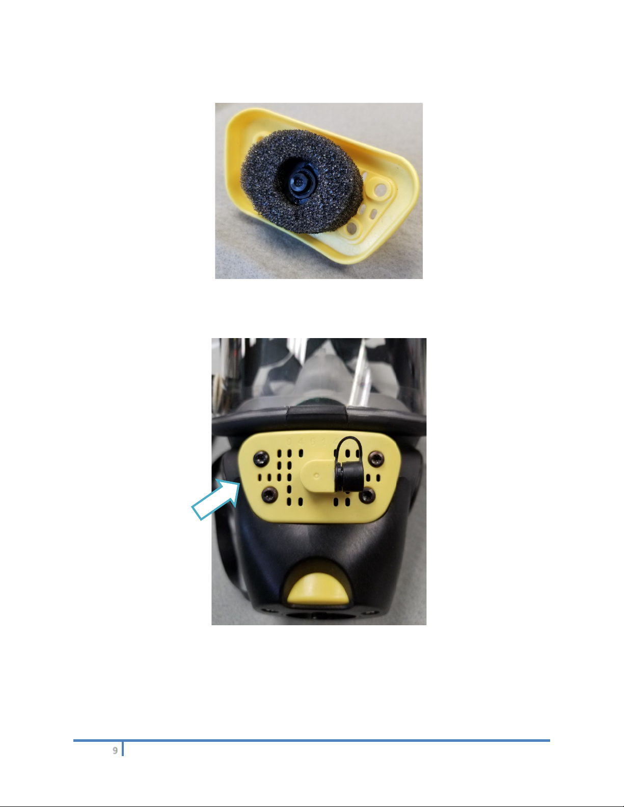
8. Position the oval-shaped foam piece around the perimeter of the PROIWT microphone as
depicted below.
9. Position the PROIWT interface assembly onto the speech body channel as depicted below. Verify
that the rubber skirt of the mask has not been forced out of the speech channel body groove.
Secure the interface into position using the four Torx screws from step 1. Hand-tighten the screws
evenly and DO NOT OVER-TIGHTEN.
10. Don the facemask and determine which microphone cable is best suited for the user. The
microphone cable will connect the interface assembly to the speaker and is supplied as a 12” or
18” length. The selected length shall not restrict head movement of the user and should be
positioned to minimize the potential for snagging. The cable contains locking connectors on both
ends. To engage the cable simply line up the contactors and press together. To disconnect the
cable, pull back on the outer shell to release.

046121 Model PROIWT Communication Interface Revision: C
User Manual
10
11. Prior to the using the system, leak test the facepiece to verify proper installation of the interface.
Leak testing can be achieved utilizing the Biomarine PRO PP Field Test Kit, part number B6-02-
5003-43-0.
12. Follow the directions provided for the speaker and radio to ready the communication system for
use.
13. To Install the Speaker and Radio Cable to the 2-Way Radio:
a) Turn the radio off. Installation of the speaker while the radio is powered may cause the radio
to transmit constantly, locking the radio system. If this occurs, turn off power to the radio.
The radio can then be powered on, restoring normal operations.
b) Remove any dust caps or covers from the radio cable connector.
c) Attach the speaker radio cable to the radio connector.
d) Tighten the mounting thumbwheel.
5.0 Communication System Use
Refer to instructions for the Innovative Wireless Technologies SENTINELTM Wireless Mesh
Communication and Tacking System for proper operation of the radio and complete system. The user
should speak in normal tones and not shout. Avoid talking when the mask is bumping or banging into
other objects as the sound waves may be picked up by the microphone and distort speech.
To speak into the facemask microphone, depress and hold the rubber side button of the speaker while
speaking.
To speak through the mask voice emitter just speak normally and the sound will transmit through the slots
in the interface cover.

046121 Model PROIWT Communication Interface Revision: C
User Manual
11
6.0 Communication System Post Use
At the completion of a mission, follow all instruction provided by Innovative Wireless Technologies to shut
down the Innovative Wireless Technologies SENTINELTM Wireless Mesh Communication and Tacking
System. Remove the microphone cable from the interface and remove the speaker and radio from the
user. The interface should remain installed in the facemask. Cover the connectors of the interface with
the supplied cap to protect. Wash and inspect the facemask as described in the BioPak 240R Benchman
Manual. Be sure that contacts of the interface connector are fully dry prior to reuse.
Warning: Make sure the contactors of the interface connector are fully dry before re-using the
facemask.
Warning: When not in use, keep the contactors of the interface protected by covering with the
included cap.
Warning: Do not allow the facemask with the interface installed to soak in disinfectant or remain
submerged in liquid for extended periods. Ten minutes is all that is required to fully
disinfect the mask.
Warning: There are no servable parts within the interface component, cables, or speaker. Do
not disassemble the components or the validity of the MSHA intrinsic safety approval
will be voided.
The front grill of the speaker can be removed for cleaning if needed. To remove the front grill, grip the
speaker in one hand, use the palm of the other hand to press down on grill and turn ¼ turn to the left.
Grill will lift out of housing. Grill can be removed to wipe away dust, dirt, moisture, etc. from inside the
cavity to ensure optimum performance. An optional debris screen, part number B2-06-6002-88-0, may be
located under the front grill and is used in those environments with intense conditions. The debris screen
can be washed with warm soapy water and replaced, when completely dry, back into the unit.
Removable Front Grill of Speaker
To remove the front grill of the speaker, reference Illustrated Parts List, grip speaker in one hand, use
palm of other hand to press down on grill and turn ¼-turn to the left. Grill will lift out of housing. Grill can
be removed to wipe away dust, dirt, moisture, etc. from inside cavity to ensure optimum performance. An
optional debris screen, B2-06-6002-88-0, may be located under the front grill for use in environments with
intense conditions. The debris screen can be washed with warm soapy water and replaced, when
completely dry, back into the speaker.
046121 Model PROIWT Communication Interface Revision: C
User Manual
12
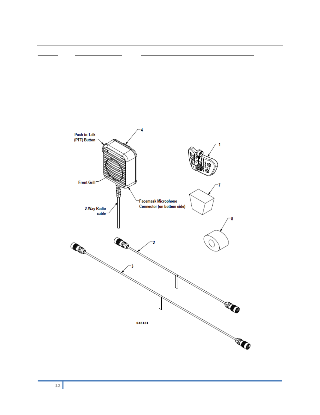
7.0 Illustrated Parts List
Item No. Part Number Description
REF B6-02-5003-61-0 PROIWT Communication Interface-Complete
1 B6-02-5003-61-1 Mask Interface Component
2 B6-01-5000-18-0 Microphone Cable, 12”
3 B6-01-5000-19-0 Microphone Cable, 18”
4 B2-06-6002-87-0 Speaker & Radio Cable
5 B2-06-6002-88-0 Optional Speaker Debris Screen (not depicted)
6 B5-06-6000-54-0 User Manual (not depicted)
7 B2-02-7001-93-0 Microphone Trapezoid Foam Pad
8 B2-02-7001-94-0 Microphone Oval Foam Pad

046121 Model PROIWT Communication Interface Revision: C
User Manual
13
(This page intentionally left blank)
Table of contents
Other CSE Safety Equipment manuals


Popular Safety Equipment manuals by other brands

ROCK
ROCK RH-2 user guide

DSSA
DSSA Combo 64 manual

ABS Safety
ABS Safety ABS-Lock X-H-24 manual

TEUFELBERGER
TEUFELBERGER hipSTAR FLEX 11,5 mm e2e Manufacturer's information and instructions for use

Helite
Helite MOTORCYCLE WIRELESS LEATHER SUIT AIRBAG... Guideline

HADEF
HADEF 59/18 Installation, operating and maintenance instructions


