manuals.online logo
Brands
  1. Home
  2. •
  3. Brands
  4. •
  5. Janus
  6. •
  7. Safety Equipment
  8. •
  9. Janus E-Series User manual

Janus E-Series User manual

System Description
The E40 safety system consists of a tansmitter detector
(TX) and a receiver detector (RX) for installation to
elevator car doors or an elevator car door and strikepost.
The detectors generate a light curtain of infra-red beams
across the elevator entrance. If a beam is broken, an
output is switched on the RX relay wires (blue, green &
yellow) to re-open the elevator doors.
Center opening Installation
1. Position each detector on the car door checking that
they are:-
+mounted approximately 12mm above the sill
+aligned with the leading door edge and plumb with
each other.
2. Use ve self-drilling Pan head screws to secure the
detector:-
+locate screws approximately 75mm from top and
bottom and equally space remaining screws between
the two points
3. Attach cables securely with the “P” clips and screws
provided:-
+avoid tight bends while providing enough slack so the
cables are not stressed or stretched as the doors move
4. Attach the green & yellow ground wire located at the
top of the antenna to the car door using a self-drilling
screw and lock washer. The ground wire must be tted
to ensure the door(s) are properly grounded. As a
check, there should be continuity between the door and
elevator car metalwork.
Janus E-Series
Installation Guide
Ref No. E40 850 GB Version 5
Fig 1: Centre-opening doors
Side-Opening Installation
1. Use the CENTRE-OPENING INSTALLATION directions
to mount the antenna on the door.
2. Remove the uPVC cover from the remaining antenna.
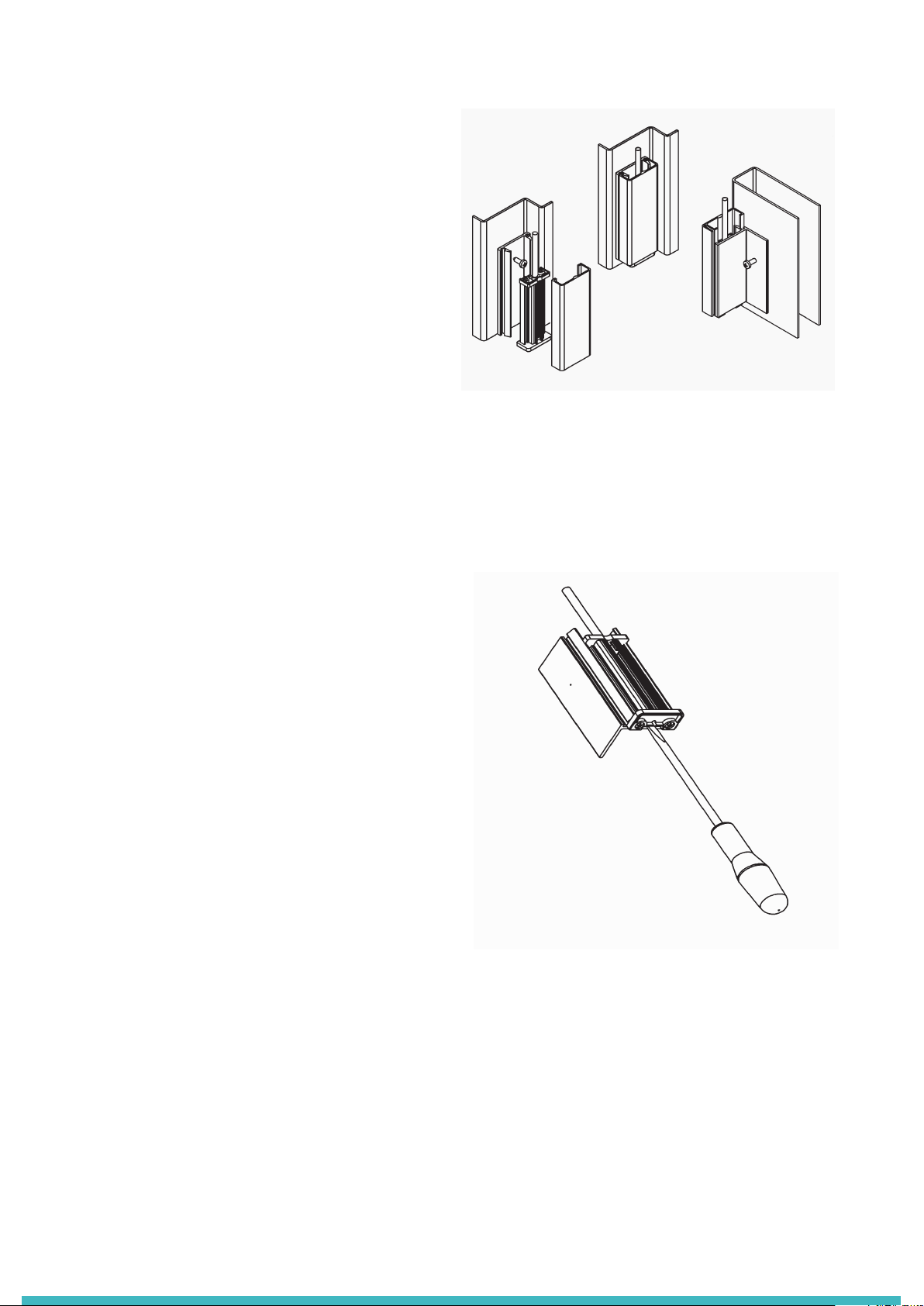
3. Using a screwdriver, pry the aluminium section from
the plastic L channel (see Fig 3).
4. Position the strikepost bracket (plastic U-shaped
channel) approximately 1/2”-3/4” above the car sill
consistent with door edge.
5. Use 5 No.8 pan-head self-tapping screws to secure
the plastic U-shaped channel to the strikepost; ensure
the screws are centred in the channel and evenly
spaced along the length of the bracket.
6. Align the aluminium channel with the bottom of the
bracket and snap into position.
7. Attach the green & yellow ground wire located at the
top of the antenna to the strikepost using a self-
tapping screw and lock washer. The ground wire must
be tted to ensure a proper ground
8. Snap on the uPVC lens.
9. Attach cable securely with the “P” clips and screws
provided.
System Connection with Model 280, see Fig 4
The Model 280 power supply provides a regulated DC
supply for the detectors and a voltage-free relay contact
to re-open the elevator doors.
1. Position the Model 280 close the centre of the car top
within reach of both RX and TX cables.
2. Plug in RX and TX cables as shown in Fig 4.
3. Connect the relay output to the “Door Re-Open” or
“Safety Edge” input of the door operator elevator
controller. The Model 280 provides voltage-free
contacts as follows:
+‘COM’ = common
+‘N/C’ = normally closed
+‘N/O’ = normally open
4. Connect the Model 280 to a 240V or 110V AC mains
supply.
5. Set SW2 NPN and SW3 to N/C.
6. When power is applied, a tone should be heard when
a person or object is detected. This tone can be
switched on or o by using SW1.
Fig 2: Strikepost Installation
Fig 3: Strikepost Installation
Direct Connection to Elevator Controller
The E40 can be directly connected to the lift controller or door operator (Fig 5). In such cases the opto-relay output
inside the E40 RX detector directly dirives the “door re-open” circuit of the lift.
Warning - direct connection requires good understanding of both lift and detector electronics. Any incompatibility
between the two systems may cause permanent damage to either. Do not apply supply voltage directly across the opto-
relay as this will result in damage. If you have any doubts then you should use a Memco 280 Power Supply instead (see
Fig 6 for 280 connection details).
Check:-
+DC - do not use an AC supply
+Regulated - do not use an unsmoothed supply
+Negative Ground - do not use a ‘positive ground’ supply (since the black 0V wire is connected to the earthed
metalwork)
+Correct Voltage - the voltage must be at least 11V and never exceed 42V DC under any circumstances
+Ripple voltage should not cause the DC supply to exceed the maximum 42V supply voltage.
+Sucient Power - the supply must be capable of supplying at least 100mA plus whatever currect is needed to dirve the
‘Door re-open’ circuit on the lift.
Note - if you have any doubts then you should use a Model 280 Power Supply
(0V) black
(Trigger Output) blue
(+24) red
(0V) black
To power supply
(+24V DC)
(+24) red
To Door re-
open circuit
RX CABLE
TX CABLE
Fig 4: Electrical Connection to 280 Power Supply
Fig 5: Electrical Connection to Life
0V - BLACK
+12V - RED/GREEN
TRIG - BLUE
NOT CONNECTED - YELLOW
0V - BLACK
+12V - RED
TX CABLE (pre-wired)
RX CABLE (pre-wired)
Power Supply
Door Re-open
Circuit
TO ELEVATOR CONTROLLER
OR DOOR OPERATOR
MODEL 280
Troubleshooting Guide
FAULT - Red LED on continuously (triggered) with no obstruction.
Check both covers are clean, remove any oor wax, dirt or scratches.
FAULT - Red LED ashes fast.
TX is not connected - verify TX detector is correctly wired.
Check both covers are clean, especially between diodes 7 and 8.
Center-opening Doors Side-opening Doors
STATUS LED ON LED OFF POSSIBLE CAUSE
Normal, Untriggered 0.5 sec 2 secs Normal Operation
Triggered Always - Obstruction between detectors
Timed-Out Beams 1 sec 1 sec One or more diodes timed out
No Signal 0.5 sec 0.5 sec Detectors not synchronised
TX not powered. All beams blocked
LED Operation
The RX detector has one LED for troubleshooting that is positioned at the top end of the detector
1.58”
0.75”
1.85” 1.85”
1.75”
1.58”
ES IG Janus V05 (GB)_PA/17.03.2015
415 Oser Avenue, Suite Q
Hauppauge, NY 11788
Phone: 631 864-3699 • 800 527-9156
Website: www.januselevator.com
E-mail: sales.us@avire-global.com

Other Janus Safety Equipment manuals

Janus Sv Series User manual

Janus

Janus Sv Series User manual

Janus PAD100-SB User manual

Janus

Janus PAD100-SB User manual

Janus AstaAmerica 500 Series User manual

Janus

Janus AstaAmerica 500 Series User manual

Janus 3M Novec 1230 User manual

Janus

Janus 3M Novec 1230 User manual

Popular Safety Equipment manuals by other brands

Guardian Diablo 2.0 SRL instruction manual

Guardian

Guardian Diablo 2.0 SRL instruction manual

ABS Safety ABS-Lock OnTop L -OT installation manual

ABS Safety

ABS Safety ABS-Lock OnTop L -OT installation manual

Helite e-Turtle 2 user guide

Helite

Helite e-Turtle 2 user guide

schmersal SLB440 operating instructions

schmersal

schmersal SLB440 operating instructions

Petzl NEST S061AA00 TECHNICAL NOTICE

Petzl

Petzl NEST S061AA00 TECHNICAL NOTICE

ABS ABS-Lock Falz III installation manual

ABS

ABS ABS-Lock Falz III installation manual

Omron F3SN-A - manual

Omron

Omron F3SN-A - manual

Christie CounterAct UR10 Installation and setup guide

Christie

Christie CounterAct UR10 Installation and setup guide

ABS ABS-Lock X-Y installation manual

ABS

ABS ABS-Lock X-Y installation manual

Revision Sawfly User instructions

Revision

Revision Sawfly User instructions

Millenium M-007-SL LOCK-ON TREESTAND instruction manual

Millenium

Millenium M-007-SL LOCK-ON TREESTAND instruction manual

Ganter Norm GN 584 Operating	 instruction

Ganter Norm

Ganter Norm GN 584 Operating instruction

Sundstrom SR 530 Operation instructions

Sundstrom

Sundstrom SR 530 Operation instructions

Kentek HTM KFPG-124F instructions

Kentek

Kentek HTM KFPG-124F instructions

ipf electronic OY32 Series Quick instruction manual

ipf electronic

ipf electronic OY32 Series Quick instruction manual

MSA AirFrame 10046846 Maintenance and Repair

MSA

MSA AirFrame 10046846 Maintenance and Repair

Werac SAFETY 40 Technical description

Werac

Werac SAFETY 40 Technical description

3M Peltor Kid 510A K manual

3M

3M Peltor Kid 510A K manual

manuals.online logo
manuals.online logoBrands
  • About & Mission
  • Contact us
  • Privacy Policy
  • Terms and Conditions

Copyright 2025 Manuals.Online. All Rights Reserved.