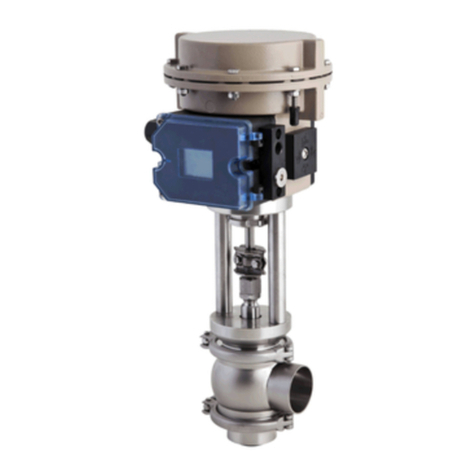
CSI Alfa Laval Unique-TO User manual

ALFA LAVAL UNIQUE MIXPROOF TANK OUTLET VALVE INSTRUCTION MANUAL—REV 8/21
TD 449-282_1
ESE00156-EN10 2021-08
Original manual
Instruction Manual
Unique-TO Mixproof Tank Outlet Valve

ALFA LAVAL UNIQUE MIXPROOF TANK OUTLET VALVE INSTRUCTION MANUAL—REV 8/21

ALFA LAVAL UNIQUE MIXPROOF TANK OUTLET VALVE INSTRUCTION MANUAL—REV 8/21
Table of contents
The information herein is correct at the time of issue but may be subject to change without prior notice
1. EC Declaration of Conformity ....................................................................... 4
2. Safety .................................................................................................... 5
2.1. Important information ............................................................................. 5
2.2. Warning signs ..................................................................................... 5
2.3. Safety precautions ................................................................................ 6
3. Installation .............................................................................................. 7
3.1. Unpacking/intermediate storage ................................................................ 7
3.2. Recycling information ............................................................................. 9
3.3. General installation ................................................................................ 9
3.4. Welding ............................................................................................ 11
4. Operation ............................................................................................... 14
4.1. Operation .......................................................................................... 14
4.2. Fault finding and repair ........................................................................... 15
4.3. Recommended cleaning ......................................................................... 16
5. Maintenance ........................................................................................... 19
5.1. General maintenance ............................................................................. 19
5.2. Dismantling of valve .............................................................................. 21
5.3. Tank plug, replacement of radial seal ........................................................... 24
5.4. Balanced plug, replacement of axial seal ....................................................... 25
5.5. Assembly of valve ................................................................................. 27
5.6. Dismantling of acutator ........................................................................... 30
5.7. Assembly of actuator ............................................................................. 32
6. Technical data ......................................................................................... 34
6.1. Technical data ..................................................................................... 34
7. Parts list and service kits ........................................................................... 36
7.1. Actuator ............................................................................................ 36
7.2. Plug setup 6 (tank flange) ........................................................................ 38
7.3. Plug setup 12 (tank flange) ...................................................................... 40
7.4. Plug setup 6 (stub flange) ........................................................................ 42
7.5. Plug setup 12 (stub flange) ...................................................................... 44
7.6. Valve bodies ....................................................................................... 46
7.7. Installation kit B ................................................................................... 48
7.8. Installation kit C ................................................................................... 50
7.9. Installation kit G ................................................................................... 52
7.10.Installation kit H and H2 .......................................................................... 54
7.11.Axial installation tool .............................................................................. 56
7.12.Radial installation tool ............................................................................ 58
7.13.Mounting tool for lip seal ......................................................................... 60
3

ALFA LAVAL UNIQUE MIXPROOF TANK OUTLET VALVE INSTRUCTION MANUAL—REV 8/21
1 EC Declaration of Conformity
Revision of Declaration of Conformity 2009-12-29
The Designated Company
Alfa Laval Kolding A/S
Company Name
Albuen 31, DK-6000 Kolding, Denmark
Address
+45 79 32 22 00
Phone No.
hereby declare that
Valve
Designation
Unique TO
Type
From serial number 1181354 - 9999999
is in conformity with the following directive with amendments:
- Machinery Directive 2006/42/EC
- Regulation (EC) No 1935/2004
- The valve is in compliance with the Pressure Equipment Directive 2014/68/EU and was subjected to the following
assessment procedure Module A. Diameters ≥DN125 may not be used for fluids group 1.
The person authorised to compile the technical file is the signer of this document
Global Product Quality Manager Pumps, Valves, Fittings and Tank Equipment Lars Kruse Andersen
Title Name
Kolding 2013-12-03
Place Date Signature
4

ALFA LAVAL UNIQUE MIXPROOF TANK OUTLET VALVE INSTRUCTION MANUAL—REV 8/21
2 Safety
Unsafe practices and other important information are emphasized in this manual.
Warnings are emphasized by means of special signs.
2.1 Important information
I
I
m
m
p
p
o
o
r
r
t
t
a
a
n
n
t
t
i
i
n
n
f
f
o
o
r
r
m
m
a
a
t
t
i
i
o
o
n
n
A
A
l
l
w
w
a
a
y
y
s
s
r
r
e
e
a
a
d
d
t
t
h
h
e
e
m
m
a
a
n
n
u
u
a
a
l
l
b
b
e
e
f
f
o
o
r
r
e
e
u
u
s
s
i
i
n
n
g
g
t
t
h
h
e
e
v
v
a
a
l
l
v
v
e
e
!
!
W
W
A
A
R
R
N
N
I
I
N
N
G
G
Indicates that special procedures m
m
u
u
s
s
t
t
be followed to avoid serious personal injury.
C
C
A
A
U
U
T
T
I
I
O
O
N
N
Indicates that special procedures m
m
u
u
s
s
t
t
be followed to avoid damage to the valve.
N
N
O
O
T
T
E
E
Indicates important information to simplify or clarify procedures.
This Instruction manual is designed to provide the user with the information to perform tasks safely for all phases in the lifetime of
the product supplied.
The user shall always read the safety section first. Hereafter the user can skip to the relevant section for the task to be carried
out or for the information needed.
This is the complete manual for the supplied product.
O
O
p
p
e
e
r
r
a
a
t
t
o
o
r
r
s
s
The operators shall read and understand the instruction manual for the supplied product.
M
M
a
a
i
i
n
n
t
t
e
e
n
n
a
a
n
n
c
c
e
e
p
p
e
e
r
r
s
s
o
o
n
n
n
n
e
e
l
l
The maintenance personnel shall read and understand the instruction manual.
The maintenance personnel or technicians shall be skilled within the field required to carry out the maintenance work safely.
T
T
r
r
a
a
i
i
n
n
e
e
e
e
s
s
Trainees can perform tasks under the supervision of an experienced employee.
P
P
e
e
o
o
p
p
l
l
e
e
i
i
n
n
g
g
e
e
n
n
e
e
r
r
a
a
l
l
The public shall not have access to the supplied product.
H
H
o
o
w
w
t
t
o
o
c
c
o
o
n
n
t
t
a
a
c
c
t
t
A
A
l
l
f
f
a
a
L
L
a
a
v
v
a
a
l
l
Contact details for all countries are
continually updated on our website.
Please visit www.alfalaval.com to access the information directly.
2.2 Warning signs
General warning: Caustic agents: Cutting danger:
5

ALFA LAVAL UNIQUE MIXPROOF TANK OUTLET VALVE INSTRUCTION MANUAL—REV 8/21
2 Safety
Unsafe practices and other important information are emphasized in this manual.
Warnings are emphasized by means of special signs.
2.3 Safety precautions
I
I
n
n
s
s
t
t
a
a
l
l
l
l
a
a
t
t
i
i
o
o
n
n
:
:
A
A
l
l
w
w
a
a
y
y
s
s
read the technical data thoroughly (see chapter 6 Technical data) !
A
A
l
l
w
w
a
a
y
y
s
s
release compressed air after use
N
N
e
e
v
v
e
e
r
r
touch the clip assembly or the actuator piston rod if the actuator is supplied with compressed air
(see warning label)
N
N
e
e
v
v
e
e
r
r
stick your fingers through the valve ports if the actuator is supplied with compressed air
O
O
p
p
e
e
r
r
a
a
t
t
i
i
o
o
n
n
:
:
A
A
l
l
w
w
a
a
y
y
s
s
read the technical data thoroughly (see chapter 6 Technical data) !
N
N
e
e
v
v
e
e
r
r
touch the clip assembly or the actuator piston rod when the actuator is supplied with compressed
air (see warning label)
N
N
e
e
v
v
e
e
r
r
pressurise air connections (AC1, AC3) simultaneously as both valve plugs can be lifted (can cause mixing)
N
N
e
e
v
v
e
e
r
r
touch the valve or the pipelines when processing hot liquids or when sterilizing.
N
N
e
e
v
v
e
e
r
r
throttle the leakage outlet
N
N
e
e
v
v
e
e
r
r
throttle the CIP outlet, if supplied
A
A
l
l
w
w
a
a
y
y
s
s
handle lye and acid with great care
M
M
a
a
i
i
n
n
t
t
e
e
n
n
a
a
n
n
c
c
e
e
:
:
A
A
l
l
w
w
a
a
y
y
s
s
read the technical data thoroughly (see chapter 6 Technical data) !
A
A
l
l
w
w
a
a
y
y
s
s
fit the seals correctly
A
A
l
l
w
w
a
a
y
y
s
s
release compressed air after use
A
A
l
l
w
w
a
a
y
y
s
s
remove the CIP connections, if supplied, before service
N
N
e
e
v
v
e
e
r
r
service the valve when it is hot
N
N
e
e
v
v
e
e
r
r
pressurise the valve/actuator when the valve is serviced
N
N
e
e
v
v
e
e
r
r
stick your fingers through the valve ports if the actuator is supplied with compressed air
N
N
e
e
v
v
e
e
r
r
touch the clip assembly or the actuator piston rod if the actuator is supplied with compressed air
(see warning label)
N
N
e
e
v
v
e
e
r
r
service the valve with valve and pipelines under pressure
A
A
l
l
w
w
a
a
y
y
s
s
use Alfa Laval genuine spare parts. The warranty of Alfa Laval products is dependent on the use of
Alfa Laval genuine spare parts.
T
T
r
r
a
a
n
n
s
s
p
p
o
o
r
r
t
t
a
a
t
t
i
i
o
o
n
n
:
:
A
A
l
l
w
w
a
a
y
y
s
s
ensure that compressed air are released
A
A
l
l
w
w
a
a
y
y
s
s
ensure that all connections is disconnected before attempting to remove the valve from the installation
A
A
l
l
w
w
a
a
y
y
s
s
drain liquid out of valves before transportation
A
A
l
l
w
w
a
a
y
y
s
s
used predesigned lifting points if defined
A
A
l
l
w
w
a
a
y
y
s
s
ensure sufficient fixing of the valve during transportation - if specially designed packaging material is available, it
must be used
S
S
T
T
O
O
R
R
A
A
G
G
E
E
Ideally, as a guide Alfa Laval recommend:
- Store supplied product as supplied in original packaging
- Port opening should be protected against any ingress
- Bare steel (not stainless) should be lightly oiled/greased
- Store in a clean, dry place without direct sunlight or UV light
- Temperature range -5 to 40°C
- Relative humidity less than 60%
- No exposure to corrosive substances (also air contained).
6

ALFA LAVAL UNIQUE MIXPROOF TANK OUTLET VALVE INSTRUCTION MANUAL—REV 8/21
3 Installation
The instruction manual is part of the delivery.
Study the instructions carefully.
Fit the warning label supplied on the valve after installation so that it is normally visible.
3.1 Unpacking/intermediate storage
S
S
t
t
e
e
p
p
1
1
C
C
A
A
U
U
T
T
I
I
O
O
N
N
!
!
Alfa Laval cannot be held responsible for incorrect unpacking.
C
C
h
h
e
e
c
c
k
k
t
t
h
h
e
e
d
d
e
e
l
l
i
i
v
v
e
e
r
r
y
y
f
f
o
o
r
r
:
:
1. Complete valve
2. Delivery note
3. Warning label
S
S
t
t
e
e
p
p
2
2
Remove upper support
TD 449-294_1
S
S
t
t
e
e
p
p
3
3
Lift out the valve.
N
N
O
O
T
T
E
E
!
!
Please note weight of valve as printed on box.
S
S
t
t
e
e
p
p
4
4
Remove possible packing materials from the valve ports.
N
N
O
O
T
T
E
E
!
!
Remember to fit leakage
detection pipe
.
TD 449-235_1
7

ALFA LAVAL UNIQUE MIXPROOF TANK OUTLET VALVE INSTRUCTION MANUAL—REV 8/21
3 Installation
The instruction manual is part of the delivery.
Study the instructions carefully.
Fit the warning label supplied on the valve after installation so that it is normally visible.
S
S
t
t
e
e
p
p
5
5
Inspect the valve for visible transport damages.
I
I
n
n
s
s
p
p
e
e
c
c
t
t
i
i
o
o
n
n
!
!
S
S
t
t
e
e
p
p
6
6
Avoid damaging the air connections, the leakage outlet, the valve
ports and the CIP connections, if supplied.
C
C
a
a
u
u
t
t
i
i
o
o
n
n
!
!
S
S
t
t
e
e
p
p
7
7
Disassemble according to illustrations 1 to 5
(please also see 5.2 Dismantling of valve).
1. Supply compressed air.
2. Remove clamp
3. Release compressed air.
4. Lift out actuator with plugs.
5. Remove clamp.
8

ALFA LAVAL UNIQUE MIXPROOF TANK OUTLET VALVE INSTRUCTION MANUAL—REV 8/21
3 Installation
Study the instructions carefully and pay special attention to the warnings!
The valve has ends for welding as standard but can also be supplied with fittings.
S
S
t
t
e
e
p
p
8
8
While valve body is welded, it is recommended to store the valve
safely in the box together with valve parts.
1. Place actuator and valve parts in the box.
2. Add supports.
3. Close, re-tape and store the box.
A
A
D
D
V
V
I
I
S
S
E
E
!
!
Mark the valve body and box with the same number before
intermediate storage.
TD 449-300_1
3.2 Recycling information
•
•
U
U
n
n
p
p
a
a
c
c
k
k
i
i
n
n
g
g
- Packing material consists of wood, plastics, cardboard boxes and in some cases metal straps
- Wood and cardboard boxes can be re-used, recycled or used for energy recovery
- Plastics should be recycled or burnt at a licensed waste incineration plant
- Metal straps should be sent for material recycling.
•
•
M
M
a
a
i
i
n
n
t
t
e
e
n
n
a
a
n
n
c
c
e
e
- During maintenance, oil and wearing parts in the machine are replaced
- All metal parts should be sent for material recycling
- Worn out or defective electronic parts should be sent to a licensed handler for material recycling
- Oil and all non-metal wear parts must be disposed off in agreement with local regulations
•
•
S
S
c
c
r
r
a
a
p
p
p
p
i
i
n
n
g
g
- At end of use, the equipment must be recycled according to the relevant, local regulations. Besides the equipment itself, any
hazardous residues from the process liquid must be considered and dealt with in a proper manner. When in doubt, or in the
absence of local regulations, please contact your local Alfa Laval sales company
3.3 General installation
S
S
t
t
e
e
p
p
1
1
- Always read the technical data thoroughly (see 6 Technical data).
- Always release compressed air after use.
- Never touch the clip assembly or the actuator piston rod if the actuator is supplied with compressed air
(see the warning label)
C
C
A
A
U
U
T
T
I
I
O
O
N
N
!
!
- Fit the supplied warning label on the valve so that it is normally visible.
- Alfa Laval cannot be held responsible for incorrect installation
N
N
O
O
T
T
E
E
!
!
- The leakage outlet must be turned downwards!
9

ALFA LAVAL UNIQUE MIXPROOF TANK OUTLET VALVE INSTRUCTION MANUAL—REV 8/21
3 Installation
Study the instructions carefully and pay special attention to the warnings!
The valve has ends for welding as standard but can also be supplied with fittings.
S
S
t
t
e
e
p
p
2
2
Avoid stressing the valve as this can result in deformation of
the sealing area and misfunction of the valve (leakage or faulty
indication).
P
P
a
a
y
y
s
s
p
p
e
e
c
c
i
i
a
a
l
l
a
a
t
t
t
t
e
e
n
n
t
t
i
i
o
o
n
n
t
t
o
o
:
:
- V
V
i
i
b
b
r
r
a
a
t
t
i
i
o
o
n
n
s
s
- T
T
h
h
e
e
r
r
m
m
a
a
l
l
e
e
x
x
p
p
a
a
n
n
s
s
i
i
o
o
n
n
o
o
f
f
t
t
h
h
e
e
t
t
u
u
b
b
e
e
s
s
(
(
e
e
s
s
p
p
e
e
c
c
i
i
a
a
l
l
l
l
y
y
a
a
t
t
l
l
o
o
n
n
g
g
t
t
u
u
b
b
e
e
l
l
e
e
n
n
g
g
t
t
h
h
s
s
)
)
- E
E
x
x
c
c
e
e
s
s
s
s
i
i
v
v
e
e
w
w
e
e
l
l
d
d
i
i
n
n
g
g
- O
O
v
v
e
e
r
r
l
l
o
o
a
a
d
d
i
i
n
n
g
g
o
o
f
f
t
t
h
h
e
e
p
p
i
i
p
p
e
e
l
l
i
i
n
n
e
e
s
s
N
N
O
O
T
T
E
E
!
!
P
P
l
l
e
e
a
a
s
s
e
e
f
f
o
o
l
l
l
l
o
o
w
w
A
A
l
l
f
f
a
a
L
L
a
a
v
v
a
a
l
l
i
i
n
n
s
s
t
t
a
a
l
l
l
l
a
a
t
t
i
i
o
o
n
n
g
g
u
u
i
i
d
d
e
e
l
l
i
i
n
n
e
e
s
s
(
(
l
l
i
i
t
t
e
e
r
r
a
a
t
t
u
u
r
r
e
e
c
c
o
o
d
d
e
e
E
E
S
S
E
E
0
0
0
0
0
0
4
4
0
0
)
)
.
.
R
R
i
i
s
s
k
k
o
o
f
f
d
d
a
a
m
m
a
a
g
g
e
e
!
!
TD 449-241
S
S
t
t
e
e
p
p
3
3
Fittings:
Ensure that the connections are tight.
R
R
e
e
m
m
e
e
m
m
b
b
e
e
r
r
s
s
e
e
a
a
l
l
r
r
i
i
n
n
g
g
s
s
!
!
S
S
t
t
e
e
p
p
4
4
Air connection: R 1/8” (BSP).
AC1: Cleaning of balanced plug.
AC2: Open valve.
AC3: Cleaning of tank plug.
S
S
t
t
e
e
p
p
5
5
CIP connection (optional extra):
1. See description of cleaning - 4.3 Recommended cleaning.
2. Connect CIP correctly
N
N
O
O
T
T
E
E
!
!
*=M
oving parts
These parts will over time turn counterclockwise until the Vent pipe
touch the edge of the intermediate piece
Must be open for
inspection!
B=CIPout
C=CIPin TD 449-251_1
B
C
10

ALFA LAVAL UNIQUE MIXPROOF TANK OUTLET VALVE INSTRUCTION MANUAL—REV 8/21
3 Installation
Study the instructions carefully and pay special attention to the warnings!
The valve has ends for welding as standard.
W
W
e
e
l
l
d
d
c
c
a
a
r
r
e
e
f
f
u
u
l
l
l
l
y
y
/
/
a
a
i
i
m
m
a
a
t
t
s
s
t
t
r
r
e
e
s
s
s
s
l
l
e
e
s
s
s
s
w
w
e
e
l
l
d
d
i
i
n
n
g
g
t
t
o
o
a
a
v
v
o
o
i
i
d
d
d
d
e
e
f
f
o
o
r
r
m
m
a
a
t
t
i
i
o
o
n
n
o
o
n
n
s
s
e
e
a
a
l
l
i
i
n
n
g
g
a
a
r
r
e
e
a
a
s
s
.
.
C
C
h
h
e
e
c
c
k
k
t
t
h
h
e
e
v
v
a
a
l
l
v
v
e
e
f
f
o
o
r
r
s
s
m
m
o
o
o
o
t
t
h
h
o
o
p
p
e
e
r
r
a
a
t
t
i
i
o
o
n
n
a
a
f
f
t
t
e
e
r
r
w
w
e
e
l
l
d
d
i
i
n
n
g
g
.
.
S
S
t
t
e
e
p
p
6
6
It is important to connect CIP inlet to the small inlet nozzle to avoid
built-up pressure in the cleaning chamber
CIP out CIP in
Align nozzle edges with recess in sealing element.
3.4 Welding
S
S
t
t
e
e
p
p
1
1
N
N
e
e
v
v
e
e
r
r
stick your fingers in the operating parts of the valve if the
actuator is supplied with compressed air. C
C
u
u
t
t
t
t
i
i
n
n
g
g
d
d
a
a
n
n
g
g
e
e
r
r
!
!
Air
S
S
t
t
e
e
p
p
2
2
Dismantle the valve in accordance with step 1, section 5.2 Dismantling of valve
11

ALFA LAVAL UNIQUE MIXPROOF TANK OUTLET VALVE INSTRUCTION MANUAL—REV 8/21
3 Installation
Study the instructions carefully and pay special attention to the warnings!
The valve has ends for welding as standard.
W
W
e
e
l
l
d
d
c
c
a
a
r
r
e
e
f
f
u
u
l
l
l
l
y
y
/
/
a
a
i
i
m
m
a
a
t
t
s
s
t
t
r
r
e
e
s
s
s
s
l
l
e
e
s
s
s
s
w
w
e
e
l
l
d
d
i
i
n
n
g
g
t
t
o
o
a
a
v
v
o
o
i
i
d
d
d
d
e
e
f
f
o
o
r
r
m
m
a
a
t
t
i
i
o
o
n
n
o
o
n
n
s
s
e
e
a
a
l
l
i
i
n
n
g
g
a
a
r
r
e
e
a
a
s
s
.
.
C
C
h
h
e
e
c
c
k
k
t
t
h
h
e
e
v
v
a
a
l
l
v
v
e
e
f
f
o
o
r
r
s
s
m
m
o
o
o
o
t
t
h
h
o
o
p
p
e
e
r
r
a
a
t
t
i
i
o
o
n
n
a
a
f
f
t
t
e
e
r
r
w
w
e
e
l
l
d
d
i
i
n
n
g
g
.
.
S
S
t
t
e
e
p
p
3
3
Bottom of tank Bottom of tank
Tank flange (standard) Stub flange (option)
A1
TD 449-253_1
11
TD 449-252_1
1=Caution 1=Caution
B
B
e
e
f
f
o
o
r
r
e
e
w
w
e
e
l
l
d
d
i
i
n
n
g
g
t
t
h
h
e
e
f
f
l
l
a
a
n
n
g
g
e
e
i
i
n
n
t
t
o
o
t
t
h
h
e
e
t
t
a
a
n
n
k
k
p
p
l
l
e
e
a
a
s
s
e
e
n
n
o
o
t
t
e
e
:
:
1. Maintain the minimum clearances "A" so that the actuator with
the internal valve parts can be removed - please see later this
section!
If there is a risk of foot damage, Alfa Laval recommends to leave
a distance of 120 mm (4.7”) below the valve (look at the specific
built-in conditions).
M
M
i
i
n
n
.
.
d
d
i
i
m
m
e
e
n
n
s
s
i
i
o
o
n
n
U
U
n
n
i
i
q
q
u
u
e
e
T
T
O
O
(all measures in mm) (1mm = 0.0394”)
L
L
o
o
n
n
g
g
s
s
t
t
r
r
o
o
k
k
e
e
D
D
N
N
/
/
O
O
D
D
D
D
N
N
/
/
O
O
D
D
2
2
”
”
2
2
½
½
”
”
3
3
”
”
4
4
”
”
D
D
N
N
2
2
½
½
”
”
3
3
”
”
D
D
N
N
S
S
i
i
z
z
e
e
5
5
1
1
6
6
3
3
.
.
5
5
7
7
6
6
.
.
1
1
1
1
0
0
1
1
.
.
6
6
5
5
0
0
6
6
5
5
8
8
0
0
1
1
0
0
0
0
1
1
2
2
5
5
1
1
5
5
0
0
6
6
3
3
.
.
5
5
7
7
6
6
.
.
1
1
6
6
3
3
8
8
0
0
with tank flange (A1)579 646 659 753 577 652 667 755 805 890 700 713 706 721
with external cleaning and tank flange (A1)616 686 699 813 614 692 707 815 865 N/A 740 753 746 761
with stub flange (A) 588 655 668 762 586 661 676 764 814 899 709 722 715 730
with external cleaning and stub flange (A) 625 695 708 822 623 701 716 824 874 N/A 749 762 755 770
If ThinkTop is mounted, add 180 mm (7.1”) to dimension
N/A = Not available
2. A
A
l
l
w
w
a
a
y
y
s
s
use welding jig (can be ordered separately at Alfa
Laval) to ensure precision of flange after welding.
O
O
n
n
l
l
y
y
use pulsed arc welding and remember no gap
between flange and tank plate.
Tack weld a
a
l
l
w
w
a
a
y
y
s
s
on the opposite side (8 segments with
filler metal).
Weld root if possible without filler metal. Welding of the
final run must be done in 8 segments to avoid crack.
Remember N
N
O
O
T
T
to dismount welding jig before flange is
cold.
Welding jig
TD 449-244_1
4
8
51
26
7
3
I
I
t
t
e
e
m
m
n
n
o
o
.
.
S
S
i
i
z
z
e
e
W
W
e
e
l
l
d
d
i
i
n
n
g
g
t
t
o
o
o
o
l
l
f
f
o
o
r
r
t
t
a
a
n
n
k
k
f
f
l
l
a
a
n
n
g
g
e
e
2”
9613099901 51 mm DN50
2½” - 3 “
9613099902 63.5 - 76.1 mm DN65 - DN80
4”
9613099903 101.6 mm DN100 - DN150
12

ALFA LAVAL UNIQUE MIXPROOF TANK OUTLET VALVE INSTRUCTION MANUAL—REV 8/21
3 Installation
Study the instructions carefully and pay special attention to the warnings!
The valve has ends for welding as standard.
W
W
e
e
l
l
d
d
c
c
a
a
r
r
e
e
f
f
u
u
l
l
l
l
y
y
/
/
a
a
i
i
m
m
a
a
t
t
s
s
t
t
r
r
e
e
s
s
s
s
l
l
e
e
s
s
s
s
w
w
e
e
l
l
d
d
i
i
n
n
g
g
t
t
o
o
a
a
v
v
o
o
i
i
d
d
d
d
e
e
f
f
o
o
r
r
m
m
a
a
t
t
i
i
o
o
n
n
o
o
n
n
s
s
e
e
a
a
l
l
i
i
n
n
g
g
a
a
r
r
e
e
a
a
s
s
.
.
C
C
h
h
e
e
c
c
k
k
t
t
h
h
e
e
v
v
a
a
l
l
v
v
e
e
f
f
o
o
r
r
s
s
m
m
o
o
o
o
t
t
h
h
o
o
p
p
e
e
r
r
a
a
t
t
i
i
o
o
n
n
a
a
f
f
t
t
e
e
r
r
w
w
e
e
l
l
d
d
i
i
n
n
g
g
.
.
S
S
t
t
e
e
p
p
4
4
W
W
a
a
r
r
n
n
i
i
n
n
g
g
!
!
Make sure to turn the valve body correctly - conical seat
downwards before welding.
N
N
O
O
T
T
E
E
!
!
Always weld the valve body into the pipeline, so that the seal ring
(76) can be replaced.
S
S
t
t
e
e
p
p
5
5
Assemble the valve in accordance with 5.5 Assembly of valve after welding.
P
P
a
a
y
y
s
s
p
p
e
e
c
c
i
i
a
a
l
l
a
a
t
t
t
t
e
e
n
n
t
t
i
i
o
o
n
n
t
t
o
o
t
t
h
h
e
e
w
w
a
a
r
r
n
n
i
i
n
n
g
g
s
s
a
a
n
n
d
d
c
c
l
l
a
a
m
m
p
p
t
t
o
o
r
r
q
q
u
u
e
e
(
(
s
s
e
e
e
e
5
5
.
.
5
5
A
A
s
s
s
s
e
e
m
m
b
b
l
l
y
y
o
o
f
f
v
v
a
a
l
l
v
v
e
e
)
)
.
.
S
S
t
t
e
e
p
p
6
6
P
P
r
r
e
e
-
-
u
u
s
s
e
e
c
c
h
h
e
e
c
c
k
k
:
:
1. Supply compressed air to AC1, AC2 and AC3 one by one.
2. Operate the valve several times to ensure that it runs smoothly.
P
P
a
a
y
y
s
s
p
p
e
e
c
c
i
i
a
a
l
l
a
a
t
t
t
t
e
e
n
n
t
t
i
i
o
o
n
n
t
t
o
o
t
t
h
h
e
e
w
w
a
a
r
r
n
n
i
i
n
n
g
g
s
s
!
!
O
O
p
p
e
e
r
r
a
a
t
t
e
e
!
!
13

ALFA LAVAL UNIQUE MIXPROOF TANK OUTLET VALVE INSTRUCTION MANUAL—REV 8/21
4 Operation
The valve is tested before delivery.
Study the instructions carefully and pay special attention to the warnings!
Pay attention to possible faults.
The items refer to the parts list and service kits section.
4.1 Operation
S
S
t
t
e
e
p
p
1
1
- A
A
l
l
w
w
a
a
y
y
s
s
read the technical data thoroughly (see 6 Technical data).
- A
A
l
l
w
w
a
a
y
y
s
s
release compressed air after use.
- N
N
e
e
v
v
e
e
r
r
touch the clip assembly or the actuator piston rod if the actuator is supplied with compressed air (see the warning label).
- N
N
e
e
v
v
e
e
r
r
pressurise air connections (AC1, AC3) simultaneously as both valve plugs can be lifted (can cause mixing).
C
C
A
A
U
U
T
T
I
I
O
O
N
N
!
!
Alfa Laval cannot be held responsible for incorrect operation.
S
S
t
t
e
e
p
p
2
2
N
N
e
e
v
v
e
e
r
r
touch the valve or the pipelines when processing hot liquids
or when sterilizing. B
B
u
u
r
r
n
n
i
i
n
n
g
g
d
d
a
a
n
n
g
g
e
e
r
r
!
!
14

ALFA LAVAL UNIQUE MIXPROOF TANK OUTLET VALVE INSTRUCTION MANUAL—REV 8/21
4 Operation
Study the maintenance instructions carefully before replacing worn parts. - See 5.1 General maintenance
4.2 Fault finding and repair
P
P
r
r
o
o
b
b
l
l
e
e
m
m
C
C
a
a
u
u
s
s
e
e
/
/
r
r
e
e
s
s
u
u
l
l
t
t
R
R
e
e
p
p
a
a
i
i
r
r
Leakage at the leakage detection
pipe (88)
- Particles between valve seats and
plug seals (56/74)
- Worn/product affected plug seal
rings (56/74)
- Plug not assembled correctly
- Remove the particles
- Check the plug seals
- Replace the plug seals
- Change rubber grade
- Assemble plug, see step 3,
section 5.5 Assembly of valve
Leakage at sealing element (48)/
upper plug (94)
Worn/product affected o-rings/lip
seal (38/39/46/49)
- Replace the o-rings/lip seal
- Change rubber grade
- Clean and if necessary replace guide
ring (45)
Leakage at clamp (64) and (65) - Too old/product affected o-rings
(76 and 47) valve body
- Loose clamp (64) or (65)
- Replace the o-rings
- Change rubber grade
- Tighten the clamp (max. 10 Nm)
CIP leakage
Leakage at spindle clamp (43)
Worn o-rings (40/67)
Damaged o-ring (39)
Worn/product affected lip seal (57)
Replace the o-rings
- Replace the o-ring
- Replace the plug seals
- Change rubber grade
Tank plug not returning to closed
position
- Wrong rubber grade
- Wrongly fitted gasket
- Mounted incorrectly (see 3.4 Welding)
- Change rubber grade
- Fit new gasket correctly
- Correct installation
Plug returns with uneven movements
(slip/stick effect)
- Wrong rubber grade
- Wrongly fitted gasket
- Mounted incorrectly (see 3.4 Welding)
- Change rubber grade
- Fit new gasket correctly
- Correct installation
15

ALFA LAVAL UNIQUE MIXPROOF TANK OUTLET VALVE INSTRUCTION MANUAL—REV 8/21
4 Operation
The valve is designed for cleaning in place (= CIP).
Study the instructions carefully and pay special attention to the warnings!
NaOH = Caustic Soda. HNO3= Nitric acid.
Internal leakage in the valve is externally visible by means of the leakage outlet.
4.3 Recommended cleaning
S
S
t
t
e
e
p
p
1
1
A
A
l
l
w
w
a
a
y
y
s
s
handle lye and acid with great care.
C
C
a
a
u
u
s
s
t
t
i
i
c
c
d
d
a
a
n
n
g
g
e
e
r
r
!
!
A
A
l
l
w
w
a
a
y
y
s
s
use
rubber gloves!
A
A
l
l
w
w
a
a
y
y
s
s
use
protective goggles!
S
S
t
t
e
e
p
p
2
2
N
N
e
e
v
v
e
e
r
r
touch the valve or the pipelines when sterilizing.
B
B
u
u
r
r
n
n
i
i
n
n
g
g
d
d
a
a
n
n
g
g
e
e
r
r
!
!
S
S
t
t
e
e
p
p
3
3
- Never throttle the leakage outlet
- Never throttle the CIP outlet, if supplied.
Risk of mixing due to overpressure).
A. = Leakage/CIP out
B. = CIP out
C. = CIP in
TD 449-247_1
A
TD 449-251_1
B
C
S
S
t
t
e
e
p
p
4
4
E
E
x
x
a
a
m
m
p
p
l
l
e
e
s
s
o
o
f
f
c
c
l
l
e
e
a
a
n
n
i
i
n
n
g
g
a
a
g
g
e
e
n
n
t
t
s
s
:
Use clean water, free from chlorides.
1. 1% by weight NaOH at 70oC (158oF) 2. 0.5% by weight HNO3at 70oC (158oF)
1 kg (2.2 lb)
NaOH +100 l (26.4 gal)
water =Cleaning agent. 0.7 l
53% HNO3
+100 l (26.4 gal)
water =Cleaning agent.
2.2 l (0.6 gal)
33% NaOH +100 l (26.4 gal)
water =Cleaning agent.
16

ALFA LAVAL UNIQUE MIXPROOF TANK OUTLET VALVE INSTRUCTION MANUAL—REV 8/21
4 Operation
The valve is designed for cleaning in place (= CIP).
Study the instructions carefully and pay special attention to the warnings!
NaOH = Caustic Soda. HNO3= Nitric acid.
Internal leakage in the valve is externally visible by means of the leakage outlet.
S
S
t
t
e
e
p
p
5
5
1. Avoid excessive concentration of the cleaning agent
⇒D
D
o
o
s
s
e
e
g
g
r
r
a
a
d
d
u
u
a
a
l
l
l
l
y
y
!
!
2. Adjust the cleaning flow to the process
M
M
i
i
l
l
k
k
s
s
t
t
e
e
r
r
i
i
l
l
i
i
z
z
a
a
t
t
i
i
o
o
n
n
/
/
v
v
i
i
s
s
c
c
o
o
u
u
s
s
l
l
i
i
q
q
u
u
i
i
d
d
s
s
⇒I
I
n
n
c
c
r
r
e
e
a
a
s
s
e
e
t
t
h
h
e
e
c
c
l
l
e
e
a
a
n
n
i
i
n
n
g
g
f
f
l
l
o
o
w
w
!
!
S
S
t
t
e
e
p
p
6
6
V
V
a
a
l
l
v
v
e
e
p
p
n
n
e
e
u
u
m
m
a
a
t
t
i
i
c
c
o
o
p
p
e
e
r
r
a
a
t
t
i
i
o
o
n
n
d
d
u
u
r
r
i
i
n
n
g
g
i
i
n
n
-
-
p
p
l
l
a
a
c
c
e
e
c
c
l
l
e
e
a
a
n
n
i
i
n
n
g
g
Each valve seat shall be lifted during the length of the cleaning cycle.
Seat lift durations shall not exceed 10 seconds.
These pneumatic functions include:
1. Upper valve seat lift (takes place during cleaning of upper valve body)
2. Lower valve seat push (takes place during cleaning of lower valve body)
The following chart presents an overview of these functions together with the recommended time durations at 21psi (1.5 bar) CIP
pressure. It is recommended to do seat lift/push in the middle of each step in the CIP sequence.
C
C
I
I
P
P
e
e
v
v
e
e
n
n
t
t
@
@
l
l
e
e
n
n
g
g
t
t
h
h
V
V
a
a
l
l
v
v
e
e
f
f
u
u
n
n
c
c
t
t
i
i
o
o
n
n
V
V
a
a
l
l
v
v
e
e
s
s
o
o
l
l
e
e
n
n
o
o
i
i
d
d
n
n
o
o
.
.
S
S
o
o
l
l
e
e
n
n
o
o
i
i
d
d
m
m
o
o
d
d
e
e
A
A
c
c
t
t
u
u
a
a
l
l
o
o
p
p
e
e
n
n
i
i
n
n
g
g
t
t
i
i
m
m
e
e
N
N
u
u
m
m
b
b
e
e
r
r
o
o
f
f
l
l
i
i
f
f
t
t
s
s
/
/
p
p
u
u
s
s
h
h
i
i
n
n
e
e
a
a
c
c
h
h
C
C
I
I
P
P
s
s
t
t
e
e
p
p
Upper seat lift 3 Energized *0.5 sec 3
Lower seat lift 2 Energized *0.5 sec 3
SpiralClean vent --
*0.5 sec 3
Warm pre-rinse @
3 minutes OD cleaning --
*5 sec 2
Upper seat lift 3 Energized *0.5 sec 3
Lower seat lift 2 Energized *0.5 sec 3
SpiralClean vent --
*0.5 sec 3
Hot alkaline wash
@10minutes OD cleaning --
*5 sec 2
Upper seat lift 3 Energized *0.5 sec 3
Lower seat lift 2 Energized *0.5 sec 3
SpiralClean vent --
*0.5 sec 3
Cold post wash @
3 minutes OD cleaning --
*5 sec 2
Upper seat lift 3 Energized *0.5 sec 3
Lower seat lift 2 Energized *0.5 sec 3
SpiralClean vent --
*0.5 sec 3
Cold acidified rinse
@ 3 minutes OD cleaning --
*5 sec 2
*Time stated is the actual opening time for the valve. Programmed duration is depended on the access to compressed air and response
time from PLC.
Variations caused by compressed air are typically:
- Long compressed air supply hoses.
- Small ID on air supply hoses.
- Limited availability of compressed air.
S
S
t
t
e
e
p
p
7
7
A
A
l
l
w
w
a
a
y
y
s
s
rinse well with clean water after the cleaning.
N
N
O
O
T
T
E
E
!
!
The cleaning agents must be stored/disposed of in accordance
with current rules/directives.
P
P
a
a
y
y
s
s
p
p
e
e
c
c
i
i
a
a
l
l
a
a
t
t
t
t
e
e
n
n
t
t
i
i
o
o
n
n
t
t
o
o
s
s
p
p
i
i
l
l
l
l
a
a
g
g
e
e
o
o
f
f
h
h
o
o
t
t
c
c
l
l
e
e
a
a
n
n
i
i
n
n
g
g
f
f
l
l
u
u
i
i
d
d
/
/
w
w
a
a
t
t
e
e
r
r
.
.
A
A
l
l
w
w
a
a
y
y
s
s
r
r
i
i
n
n
s
s
e
e
!
!
Clean water Cleaning agents
17

ALFA LAVAL UNIQUE MIXPROOF TANK OUTLET VALVE INSTRUCTION MANUAL—REV 8/21
4 Operation
The valve is designed for cleaning in place (= CIP).
Study the instructions carefully and pay special attention to the warnings!
NaOH = Caustic Soda. HNO3= Nitric acid.
Internal leakage in the valve is externally visible by means of the leakage outlet.
S
S
t
t
e
e
p
p
8
8
1
1
.
.
C
C
l
l
o
o
s
s
e
e
d
d
v
v
a
a
l
l
v
v
e
e
A=Product
B= CIP
TD 449-293_1
A
B
S
S
t
t
e
e
p
p
9
9
2
2
.
.
S
S
e
e
a
a
t
t
l
l
i
i
f
f
t
t
c
c
l
l
e
e
a
a
n
n
i
i
n
n
g
g
w
w
i
i
t
t
h
h
t
t
a
a
n
n
k
k
p
p
l
l
u
u
g
g
(
(
o
o
p
p
t
t
i
i
o
o
n
n
a
a
l
l
)
)
(see step 6 page 19)
A=CIP
B=Product
C=CIPout
TD 449-291_1
A
B
C
S
S
t
t
e
e
p
p
1
1
0
0
3
3
.
.
O
O
p
p
e
e
n
n
v
v
a
a
l
l
v
v
e
e
A=Produ
ct
B = Leakage detecting
TD 449-292_1
A
B
S
S
t
t
e
e
p
p
1
1
1
1
4
4
.
.
S
S
e
e
a
a
t
t
l
l
i
i
f
f
t
t
c
c
l
l
e
e
a
a
n
n
i
i
n
n
g
g
w
w
i
i
t
t
h
h
b
b
a
a
l
l
a
a
n
n
c
c
e
e
d
d
p
p
l
l
u
u
g
g
(seeStep 6, )
A=Product
B=CIP
C=CIPout
A
B
C
TD 449-289_1
18

ALFA LAVAL UNIQUE MIXPROOF TANK OUTLET VALVE INSTRUCTION MANUAL—REV 8/21
5 Maintenance
Maintain the valve/actuator regularly.
Study the instructions carefully and pay special attention to the warnings!
Always use genuine Alfa Laval spare parts, and keep spare rubber seals and guide rings in stock. Store seals in closed bag.
The items refer to the parts list and service kits section.
5.1 General maintenance
S
S
t
t
e
e
p
p
1
1
- A
A
l
l
w
w
a
a
y
y
s
s
read the technical data thoroughly (see 6 Technical data).
- A
A
l
l
w
w
a
a
y
y
s
s
fit the seals correctly (risk of mixing).
- A
A
l
l
w
w
a
a
y
y
s
s
release the compressed air after use.
- A
A
l
l
w
w
a
a
y
y
s
s
remove the CIP connections, if supplied, before service.
N
N
O
O
T
T
E
E
!
!
All scrap must be stored/disposed of in accordance with current rules/directives.
S
S
t
t
e
e
p
p
2
2
- N
N
e
e
v
v
e
e
r
r
service the valve when it is hot.
- N
N
e
e
v
v
e
e
r
r
service the valve with valve/actuator under pressure
- N
N
e
e
v
v
e
e
r
r
service the valve with fluid in the tank. A
A
t
t
m
m
o
o
s
s
p
p
h
h
e
e
r
r
i
i
c
c
p
p
r
r
e
e
s
s
s
s
u
u
r
r
e
e
r
r
e
e
q
q
u
u
i
i
r
r
e
e
d
d
!
!
B
B
u
u
r
r
n
n
i
i
n
n
g
g
d
d
a
a
n
n
g
g
e
e
r
r
!
!
S
S
t
t
e
e
p
p
3
3
N
N
e
e
v
v
e
e
r
r
stick your fingers in operating parts of the valve if the
actuator is supplied with compressed air.
C
C
u
u
t
t
t
t
i
i
n
n
g
g
d
d
a
a
n
n
g
g
e
e
r
r
!
!
Air
TD 449-256_1
S
S
t
t
e
e
p
p
4
4
N
N
e
e
v
v
e
e
r
r
touch the clip assembly or the actuator piston rod if the
actuator is supplied with compressed air (see the warning label).
Moving
parts!
Air
TD 449-257_1
19

ALFA LAVAL UNIQUE MIXPROOF TANK OUTLET VALVE INSTRUCTION MANUAL—REV 8/21
5 Maintenance
Maintain the valve/actuator regularly.
Study the instructions carefully and pay special attention to the warnings!
Always use genuine Alfa Laval spare parts, and keep spare rubber seals and guide rings in stock. Store seals in closed bag.
The items refer to the parts list and service kits section.
R
R
e
e
c
c
o
o
m
m
m
m
e
e
n
n
d
d
e
e
d
d
s
s
p
p
a
a
r
r
e
e
p
p
a
a
r
r
t
t
s
s
:
:
S
S
e
e
r
r
v
v
i
i
c
c
e
e
k
k
i
i
t
t
s
s
(
(
s
s
e
e
e
e
6
6
T
T
e
e
c
c
h
h
n
n
i
i
c
c
a
a
l
l
d
d
a
a
t
t
a
a
)
)
Order service kits from the service kits section (see 6 Technical data)
O
O
r
r
d
d
e
e
r
r
i
i
n
n
g
g
s
s
p
p
a
a
r
r
e
e
p
p
a
a
r
r
t
t
s
s
: Contact the Sales Department.
The valve is designed so that internal leakages do not result in the products becoming mixed.
Internal leakage in the valve is externally visible. Study the instructions carefully.
Always keep spare rubber seals and guide rings in stock. Check the valve for smooth operation after service.
V
V
a
a
l
l
v
v
e
e
r
r
u
u
b
b
b
b
e
e
r
r
s
s
e
e
a
a
l
l
s
s
V
V
a
a
l
l
v
v
e
e
p
p
l
l
u
u
g
g
s
s
e
e
a
a
l
l
s
s
V
V
a
a
l
l
v
v
e
e
g
g
u
u
i
i
d
d
e
e
r
r
i
i
n
n
g
g
s
s
Preventive maintenance R
R
e
e
p
p
l
l
a
a
c
c
e
e
a
a
f
f
t
t
e
e
r
r
1
1
2
2
m
m
o
o
n
n
t
t
h
h
s
s
(
(
*
*
)
)
R
R
e
e
p
p
l
l
a
a
c
c
e
e
a
a
f
f
t
t
e
e
r
r
1
1
2
2
m
m
o
o
n
n
t
t
h
h
s
s
(
(
*
*
)
)
Replace when required
Maintenance after leakage
(leakage normally starts slowly)
R
R
e
e
p
p
l
l
a
a
c
c
e
e
a
a
f
f
t
t
e
e
r
r
p
p
r
r
o
o
d
d
u
u
c
c
t
t
i
i
o
o
n
n
c
c
y
y
c
c
l
l
e
e
R
R
e
e
p
p
l
l
a
a
c
c
e
e
a
a
f
f
t
t
e
e
r
r
p
p
r
r
o
o
d
d
u
u
c
c
t
t
i
i
o
o
n
n
c
c
y
y
c
c
l
l
e
e
Planned maintenance - Regular inspection for
leakage and smooth
operation
- Keep a record of the valve
- Use the statistics for
planning of inspections
- Regular inspection for
leakage and smooth
operation
- Keep a record of the valve
- Usethest
atistics for
planning of inspections
Replace when required
Lubrication W
W
h
h
e
e
n
n
a
a
s
s
s
s
e
e
m
m
b
b
l
l
i
i
n
n
g
g
Alfa Laval
Silicon based
Food-grade Lubricant
USDA H1 approved grease
W
W
h
h
e
e
n
n
a
a
s
s
s
s
e
e
m
m
b
b
l
l
i
i
n
n
g
g
Alfa Laval
Silicon based
Food-grade Lubricant
USDA H1 approved grease
N
N
o
o
n
n
e
e
N
N
O
O
T
T
E
E
!
!
Lubricate thread in valve plug parts with Alfa Laval Lubricant or similar.
(*) Depending on working conditions! Please contact Alfa Laval.
(**) All products wetted seals.
R
R
e
e
p
p
a
a
i
i
r
r
i
i
n
n
g
g
o
o
f
f
a
a
c
c
t
t
u
u
a
a
t
t
o
o
r
r
:
- The actuator is maintenance-free but repairable.
- If repair is required, replacing all actuator rubber seals is recommended.
- Lubricate seals with Molykote Longterm 2 (black).
- To avoid possible black remains on pos. 1 and 29, Alfa Laval recommends Alfa Laval Lubricant for these two positions.
P
P
r
r
e
e
-
-
u
u
s
s
e
e
c
c
h
h
e
e
c
c
k
k
1. Supply compressed air to AC1, AC2 and AC3 one by one.
2. Operate the valve several times to ensure that it operates
smoothly.
P
P
a
a
y
y
s
s
p
p
e
e
c
c
i
i
a
a
l
l
a
a
t
t
t
t
e
e
n
n
t
t
i
i
o
o
n
n
t
t
o
o
t
t
h
h
e
e
w
w
a
a
r
r
n
n
i
i
n
n
g
g
s
s
!
!
O
O
p
p
e
e
r
r
a
a
t
t
e
e
!
!
20
Table of contents
Other CSI Control Unit manuals
Popular Control Unit manuals by other brands

NI
NI PXIe-6674T user manual

Newhaven Display International
Newhaven Display International NHD-1.69-AU-SHIELD user guide

Rockwell Automation
Rockwell Automation Trusted TMR manual

Toshiba
Toshiba HX7 Series Specifications

Graff
Graff IMMERSION 2150250 Instructions for assembly and use

Raspberry Pi
Raspberry Pi 52PI-RPI-UART user manual

ADTRAN
ADTRAN 1200791L1 quick start guide

Seeed
Seeed Grove GPS Air530 manual

Hubner
Hubner UO-EM-EGS41 Operating and assembly instructions

LEAMING INDUSTRIES
LEAMING INDUSTRIES AGC432 Instruction book

Vimar
Vimar by-me 01958 instruction sheet

STIEBEL ELTRON
STIEBEL ELTRON FES KOMFORT Operation and installation