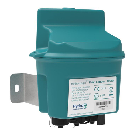
CSS CANedge2 User manual

CANedge2 Docs
Release FW 01.04.02
Mar 31, 2021


CONTENTS
0.1 CANedge2 documentation ................................... 1
0.1.1 About this manual ................................... 1
0.1.2 Legal information .................................... 2
0.2 Specification ........................................... 4
0.2.1 CAN-bus (x2) ...................................... 4
0.2.2 LIN-bus (x2) ...................................... 4
0.2.3 Logging ......................................... 5
0.2.4 Real-time clock (RTC) ................................. 5
0.2.5 Electrical ........................................ 5
0.2.6 Mechanical ....................................... 6
0.2.7 Connectivity ....................................... 6
0.3 Hardware ............................................. 7
0.3.1 Installation ....................................... 7
0.3.2 Connector ........................................ 8
0.3.3 Enclosure ........................................ 10
0.3.4 SD card ......................................... 10
0.3.5 LED ........................................... 12
0.3.6 Label ........................................... 13
0.4 Configuration ........................................... 14
0.4.1 General ......................................... 14
0.4.2 Logging ......................................... 16
0.4.3 Real-Time-Clock .................................... 19
0.4.4 Secondary port ..................................... 20
0.4.5 CAN ........................................... 21
0.4.6 LIN ........................................... 40
0.4.7 Connect ......................................... 44
0.5 Device file ............................................ 46
0.6 Log file .............................................. 47
0.6.1 Organization ...................................... 47
0.6.2 MDF ........................................... 47
0.7 Remote access .......................................... 49
0.7.1 Network ......................................... 49
0.7.2 Server .......................................... 49
0.7.3 Managing devices .................................... 51
0.7.4 Security ......................................... 54
0.8 Firmware ............................................. 60
0.8.1 Firmware download ................................... 60
0.8.2 Firmware versioning & naming ............................ 60
0.8.3 Firmware upgrade ................................... 61
i

ii

CANedge2 Docs, Release FW 01.04.02
0.1 CANedge2 documentation
0.1.1 About this manual
0.1.1.1 Purpose
This manual describes the functionality of the CANedge2 (firmware 01.04.02) with focus on:
1. Hardware & installation
2. Configuration
3. Firmware upgrade
4. Remote access
This manual does not provide details on available software/API tools.
0.1.1.2 Other documentation
The CANedge1 Intro and CANedge2 Intro provide practical guides for getting started. The intros also
detail software & API tools that can be used with the CANedge.
0.1.1.3 Notation used
The following notation is used throughout this documentation:
Admonitions
Note: Used to highlight supplementary information
Warning: Used if incorrect use may result in major loss of data and/or time
Danger: Used if incorrect use may result in damage to the device, personal injury or death
Number bases
When relevant, the base of a number is written explicitly as 𝑥𝑦, with 𝑦as the base.
The following number bases are used throughout this documentation:
•Binary (𝑦= 2). Example: The binary number 10101010 is written as 101010102
•Decimal (𝑦= 10). Example: The decimal number 170 is written as 17010
•Hexadecimal (𝑦= 16). Example: The hexadecimal number 𝐴𝐴 is written as 𝐴𝐴16
The value of a number is the same regardless of the base (e.g. the values in above examples are equal
101010102= 17010 =𝐴𝐴16). However, it is sometimes more convenient to represent the number using a
specific base.
0.1. CANedge2 documentation 1

CANedge2 Docs, Release FW 01.04.02
0.1.2 Legal information
0.1.2.1 Usage warning
Warning: Carefully review the below usage warning before installing the product
The use of the CANedge device must be done with caution and an understanding of the risks involved.
The operation of the device may be dangerous as you may affect the operation and behavior of a CAN
bus system.
Improper installation or usage of the device can lead to serious malfunction, loss of data, equipment
damage and physical injury. This is particularly relevant when the device is physically connected to
a CAN based application that may be controlled via the CAN bus. In this setup you can potentially
cause an operational change in the system, turn on/off certain modules and functions or change to an
unintended mode.
While the device supports a high degree of security in regards to wireless data transfer and over-the-air
updates, it is recommended that these features are used with caution. Incorrect usage of this functionality
can result in a device being unable to connect to your server. Further, changing transmit messages over-
the-air should be done with extreme caution.
The device should only be used by persons who are qualified/trained, understand the risks and understand
how the device interacts with the system in which it is integrated.
0.1.2.2 Terms & conditions
Please refer to our general terms & conditions.
0.1.2.3 Electromagnetic compatibility
The CANedge has been tested in accordance with CE, FCC and IC standards.
Certificates are available in the online documentation.
Wifi enabled CANedge devices include the following pre-certificed wireless module: ATWINC1500U.
Note that the ATWINC15x0-MR210UB module has been tested with an external whip antenna with a
gain of 2.2dBi.
The device is in conformity with all provisions of Annex II of Council Directive 2014/30/EU, in its latest
amended version, referred to EMC directive.
The device complies with Part 15 of the FCC Rules. Operation is subject to the following two conditions:
(1) this device may not cause harmful interference, and (2) this device must accept any interference
received, including interference that may cause undesired operation.
The device complies with the requirements set forth in the Innovation, Science and Economic Develop-
ment Canada (ISED) Rules and Regulations ICES-003 Class B and the measurement procedure according
to CAN/CSA CISPR 22-10.
Specifically, it is in conformity with the following standards:
EN 55032:2015 - Electromagnetic Compatibility of Multimedia Equipment
EN 55024:2010+A1:2015 - IT equipment. Immunity characteristics. Limits and methods of
˓→measurement
FCC Rules and Regulations Part 15 Subpart B: 2018
ICES-003: Issue 6 January 2016
2 CONTENTS

CANedge2 Docs, Release FW 01.04.02
0.1.2.4 Voltage transient tests
The CANedge has passed below ISO 7637-2:2011 tests, performed by TÜV SÜD:
ISO 7637-2:2011: Voltage transient emissions test on supply lines
ISO 7637-2:2011: Transient immunity test on supply lines
0.1.2.5 Contact details
For any questions regarding our products, please contact us:
CSS Electronics
EU VAT ID: DK36711949
Soeren Frichs Vej 38K (Office 35), 8230 Aabyhoej, Denmark
contact[AT]csselectronics.com
+45 91252563
www.csselectronics.com
0.1. CANedge2 documentation 3

CANedge2 Docs, Release FW 01.04.02
0.2 Specification
0.2.1 CAN-bus (x2)
•Physical
–Two physical CAN-bus interfaces
–Industry standard DB9 (D-sub9) connectors
•Transceiver
–Compliant with CAN Protocol Version 2.0 Part A, B and ISO 11898-1
–Compliant with ISO CAN FD and Bosch CAN FD
–Ideal passive behavior when unpowered (high impedance / no load)
–Protection: ±16kV HBM ESD, ±15kV IEC ESD, ±70 V bus fault, short circuit
–Common mode input voltage: ±30V
–TXD dominant timeout (prevents network blocking in the event of a failure)
–Data rates up to 5Mbps1
•Controller
–Based on MCAN IP from Bosch
–Bit-rate: Auto-detect (from list2), manual simple (from list3) or advanced (bit-timing)
–128 standard CAN ID + 64 extended CAN ID filters (per interface)
–Advanced filter configuration: Range, mask, acceptance, rejection, down sampling
–Configurable transmit messages, single shot or periodic (up to 128/64 regular/extended)
–Support for Remote-Transmission-Request (RTR) frames
–Silent mode: Restricted (acknowledge only) or monitoring (transmission disabled)
–Supports all CAN based protocols (J1939, CANopen, OBD2, NMEA 2000, . . . )4
•Application
–Control reception (logging) and transmission states using CAN-bus control message
–Heartbeat signal to broadcast device time, space left of SD-card and rx/tx state
0.2.2 LIN-bus (x2)
•Physical
–Two physical LIN-bus interfaces
–Industry standard DB9 (D-sub9) connectors
•Transceiver
–Protection: ±8kV HBM ESD, ±1.5kV CDM, ±58V bus fault
–Supports 4V to 24V applications
–TXD dominant timeout (prevents network blocking in the event of a failure)
–Data rates up to 20kbps
1Supported FD bit-rates: 1M, 2M, 4M
2Bit-rate list: 5k, 10k, 20k, 33.333k, 47.619k, 50k, 83.333k, 95.238k, 100k, 125k, 250k, 500k, 800k, 1M
3Bit-rate list: 5k, 10k, 20k, 33.333k, 47.619k, 50k, 83.333k, 95.238k, 100k, 125k, 250k, 500k, 800k, 1M, 2M, 4M
4The device logs raw data frames
4 CONTENTS

CANedge2 Docs, Release FW 01.04.02
•Controller
–Support for both publisher and subscriber modes
–Automatic5and custom frame lengths
–Classic and Extended checksum formats
–Configurable transmit messages, single shot or periodic
0.2.3 Logging
•Extractable industry grade micro SD-card (8-32GB)
•Standard FAT file system (can be read directly by a PC)
•Logging to industry standard .MF4 (ASAM MDF4) file format
•Simultaneous logging from 2 x CAN-bus + 2 x LIN-bus
•Message time stamping with 50 us resolution
•Supports cyclic logging mode (oldest log file is deleted when memory is full)
•Log file splitting based on file size or time
•Session number (power cycle) log file naming (groups log files)
•Globally unique ID for each device ensures unique log file naming
•Power safe (device can be disconnected during logging without corrupting data)
•High-performance logging6
0.2.4 Real-time clock (RTC)
•High precision real-time clock retains date and time when device is off
•For WiFi-enabled devices, the real-time clock can be synced with an NTP time server
0.2.5 Electrical
•Device supply
–Channel 1 voltage supply range: +7.0V to +32V DC7
–Reverse voltage protection8
–Transient voltage event protection on supply lines9
–Consumption:
∗CANedge1: 0.8W
∗CANedge2: 1W
•Secondary port output supply10
–Configurable output supply on connector 2 (CH2), fixed 5V up to 1.5A11
–Supports power out scheduling to control the output state based on time of day
5Data lengths are defined by bits 4 and 5 of the LIN identifier
6See the performance tests
7The device is supplied from connector 1 (CH1)
8Up to 24V
9The transient voltage protection is designed to clamp low energy voltage events. High energy voltage events may
overheat and destroy the input protection
10 Can be used to supply external devices
11 The 5V output can be used to power WiFi hotspots, sensors, small actuators, external LEDs, etc.
0.2. Specification 5

CANedge2 Docs, Release FW 01.04.02
0.2.6 Mechanical
•Status indicated using external LEDs
•Robust aluminum enclosure
•Dimensions: 50.2 x 83.4 x 24.5 mm (L x W x H)12
•Weight: 100g
•Operating temperature: -25 degC to +70 degC
0.2.7 Connectivity
•Physical
–SMA connector for external antenna13
–The included dipole antenna has a max gain of 2dBi
•WiFi
–Single-band 2.4 GHz
–Supports IEEE 802.11 b/g/n
–Supports “open” and WPA/WPA2 security settings
–Configurable prioritized list of 1-5 WiFi access points
–WiFi module certified in USA, Canada, Europe, Japan, Korea, China, India, Taiwan
•File transfer
–HTTP/HTTPS file transfer
–S3 transfer protocol1415
–Device identification using globally unique device ID
–Automatic push of log files to remote or local server
–Automatic time synchronization
•Security
–Secure file transfer using TLS 1.2
–Credentials stored on the device can be encrypted
•Over-The-Air (OTA)
–OTA firmware updates (no need for proprietary software)
–OTA configuration updates (no need for proprietary software)
•WiFi heartbeat
–Lets the device periodically upload a small device status file
12 Without external antenna
13 See the installation section for details on e.g. exchanging the antenna
14 Open S3 API allows automated management of server objects
15 Can be used with Amazon Web Services S3, Google Cloud, Microsoft Azure (via gateway) and several self-hosted
open source solutions
6 CONTENTS

CANedge2 Docs, Release FW 01.04.02
0.3 Hardware
0.3.1 Installation
This section outlines the installation requirements that shall be satisfied.
0.3.1.1 Supply quality
The nominal voltage shall be kept within specifications at all times. The device is internally protected
against low energy voltage events which can be expected as a result of supply wire noise, ESD and
stub-wire inductance.
If the supply line is shared with inductive loads, care should be taken to ensure high energy voltage events
do not reach the device. Automotive environments often include several sources of electrical hazards,
such as load dumps (disconnection of battery while charging), relay contacts, solenoids, alternator, fuel
injectors etc. The internal protection circuitry of the device is not capable of handling high energy
voltage events directly from such sources.
0.3.1.2 Grounding
ISO 11898-2 tolerates some level of ground offset between nodes. To ensure the offset remains within
range, it is recommended to use a single point ground reference for all nodes connected to the CAN-bus.
This may require the ground wire to be carried along with data wires.
If a secondary CAN-bus network is connected to Channel 2, care must be taken to ensure that the ground
potentials of the two networks can safely be connected through the common ground in the device.
0.3.1.3 Cable shielding
Shielding is not needed in all applications. If shielding is used, it is recommended that a short pig-tail
be crimped to the shield end at each connector.
0.3.1.4 CAN ISO 11898-2
ISO 11898-2 defines the basic physical requirements of a high-speed CAN-bus network. Some of these
are listed below:
•Max line length (determined by bit-rate)
•Line termination (120 ohm line termination at each end of data line)
•Twisted data lines
•Ground offsets in range -2V to +7V
0.3.1.5 CAN-bus stub length
It is recommended that the CAN-bus stub length is kept short. The stub length is defined as the length
from the ”main” data line wires to the connection point of the CAN-bus nodes.
0.3.1.6 Enclosure caution
The device is not intended for use without the enclosure.
0.3. Hardware 7

CANedge2 Docs, Release FW 01.04.02
Warning: Opening the enclosure can permanently damage the device due to e.g. ESD (electrostatic
discharge) - and improper handling may void the warranty
0.3.1.7 Mounting
The device should be mounted in a way that minimizes vibration exposure and accounts for the IP rating
of the device.
0.3.1.8 Antenna
The device uses an external WiFi antenna. The antenna satisfies the constraints under which the
contained WiFi module has been tested - in particular, it has a max gain of 2dBi. The antenna can be
replaced or extended.
If you need to re-orient, disconnect, re-connect or tighten the antenna, you should use the proper tight-
ening mechanism. Specifically, you should not directly turn the antenna (as this may loosen the internal
connection to the PCB) - rather, you should first loosen the nut, after which you can e.g. re-orient the
antenna and then re-tighten the nut.
It is critical that the antenna is properly connected at all times and that it is not loose when the CANedge
is powered on. Operation with a loose antenna or without the antenna entirely can damage the device.
0.3.2 Connector
0.3.2.1 Pinout
The CANedge uses two D-sub9 connectors for supply, 2 x CAN, 2 x LIN and a 5 V Supply Output.
Make sure to refer to the pinout matching the product hardware revision (see the label).
8 CONTENTS

CANedge2 Docs, Release FW 01.04.02
Hardware revision ≥00.01
Pin # Channel 1 (CH1) Channel 2 (CH2)
1 NC 5V Supply Output
2 CAN 1 L CAN 2 L
3 GND GND
4 LIN Data 1 LIN Data 2
5 NC NC
6 GND (optional) GND (optional)
7 CAN 1 H CAN 2 H
8 NC NC
9 Supply & LIN1 VBAT LIN2 VBAT
Hardware revision = 00.00
The hardware 00.00 pinout can be found here.
Supply
The supply (CH1 pin 9) is used to power the device. The supply is internally protected against reverse
polarity and low-energy voltage spikes.
Refer to the Electrical Specification for more details on the device supply.
Warning: The supply line must be protected against high-energy voltage events exceeding device
limits
GND
All GND (ground) pins are connected internally.
5 V Supply Output
The +5 V output can be used to power external devices. The power can be toggled via the device
configuration. The output can deliver 1.5 A @ 5 V continuously.
Danger: Connecting external input power to this pin can permanently damage the device
Warning: External protection (such as clamp diodes) must be installed if inductive loads are
connected to the 5V Supply Output
CAN L/H
Warning: CAN-bus requires no common reference (ground). However, it is recommended that
GND (ground) is carried along with CAN-L/H to prevent that the common-mode voltage is exceeded
(resulting in transceiver damage)
0.3. Hardware 9

CANedge2 Docs, Release FW 01.04.02
LIN VBAT
The LIN-bus positive reference. Supports systems operating from 4V to 24V.
•LIN1 VBAT: Pin is shared with device supply and shares the supply input protection circuit
•LIN2 VBAT: Tolerates voltage spikes up to 48V. Spikes above this can damage the interface
LIN Data
LIN-bus single-wire data line referenced to LIN VBAT.
0.3.2.2 Basic wiring example
Below example illustrates how the CANedge CAN-bus 1 (channel 1) can be connected.
o--o--------------------o------------ ... ---o-----------o CAN 1 H (pin 7)
| | | | |
+++ | | | +++
|R| | | | |R|
+++ | | | +++
| | | | |
o-----------o--------------------o--- ... ------------o--o CAN 1 L (pin 2)
|CANedge | | Node 1 | | Node N |
+--+--------+--+ +--+--------+--+ +--+--------+--+
| CANH CANL| | CANH CANL| | CANH CANL|
| | | | | |
| Supply GND | | Supply GND | | Supply GND |
+--+--------+--+ +--+--------+--+ ... +--+--------+--+
| | | | | |
o--------------------o------------ ... ---o-----------o SUPPLY (pin 9)
|||
o--------------------o--- ... ------------o--o GND (pin 3)
0.3.3 Enclosure
The CANedge uses a robust aluminium enclosure - PDF drawings and 3D STEP files can be found in
the online documentation.
0.3.4 SD card
The CANedge uses an extractable SD-card to store device configuration and log files.
Warning: Never extract the SD-card while the device is on. Remove power first and wait a few
seconds for the device to turn off.
0.3.4.1 File organization
The files stored on the SD-card are organized as illustrated by below example:
/
config-XX.XX.json
schema-XX.XX.json
device.json
(continues on next page)
10 CONTENTS

CANedge2 Docs, Release FW 01.04.02
(continued from previous page)
LOG/
[DEVICE_ID]
00000001
00000001.MF4
00000002.MF4
...
...
00000002
00000001.MF4
00000002.MF4
...
...
...
...
•config-XX.XX.json: Configuration File (device configuration)
•schema-XX.XX.json: Rule Schema (configuration rules)
•device.json: Device File (device information)
•LOG/: Path for log files
For more information on the specific files, refer to the documentation menu.
Log files
Log files are stored in LOG/[DEVICE_ID]/[SESSION_NUMBER]/[SPLIT_NUMBER].[FILE_EXTENSION]. For
more information on the structure of the log files, refer to the log file section.
0.3.4.2 Type
The CANedge uses a specifically selected industrial graded SD-card with special timing constraints to
ensure safe shutdown when power is lost.
Warning: The device cannot be guaranteed to work if the pre-installed SD-card is replaced
Exchanging SD cards between devices
The SD card is not “locked” to the device. If the card is replaced, be aware of the following points:
•Critical device specific data are not stored on the SD card (e.g. device ID)
•Non-critical meta data are stored on the SD card (e.g. log file session number)
•If the card is replaced by a card from another device, it is recommended to clear the card first
•It may be necessary to update the configuration file if it contains device specific settings
0.3.4.3 Lifetime
The SD-card memory wears as any other flash based memory. The industrial graded SD-cards provided
with the CANedge have the following guaranteed minimum endurance numbers1:
1TBW: Terabytes Written
0.3. Hardware 11

CANedge2 Docs, Release FW 01.04.02
Size [GB] TBW Lifetime @ 1MB/sec [years]2Lifetime @ 1MB/min [years]
8 24 0.8 47.9
32 96 3.2 191.5
0.3.5 LED
0.3.5.1 Location
The LEDs are located at the back of the device as illustrated below.
0.3.5.2 Overview
LED Short Name LED Color Main Function
PWR Green Power
CH1 Yellow Bus activity on connector 1
(CH1)
CH2 Yellow Bus activity on connector 2
(CH2)
MEM Red Memory card activity
WFI Blue WiFi connected
PWR
The Power LED is constantly on when the device is in normal operation. An exception is when the
firmware is being updated (for more information go to the Firmware section).
CH1 / CH2
The Channel 1 /Channel 2 LEDs indicate bus activity on Channel 1 and 2 respectively.
MEM
The Memory LED indicates activity on the memory card. Config file parsing, message logging, file
upload etc. all generate activity on the memory card.
2A constant logging rate of 1 MB/sec is likely much much higher than in any practical logging use-case
12 CONTENTS

CANedge2 Docs, Release FW 01.04.02
WFI
The WiFi LED is on when the device is connected to a WiFi access point.
Note: The device only connects to WiFi when a transfer is pending and is otherwise disconnected
(LED off)
0.3.6 Label
A unique label is attached to the back of each device. Examples of the labels are illustrated below.
Note: The data matrix can be scanned to simplify installation of a new device
The label holds the following information:
•Device type: CANedge2
•Production data in format YYYYWW (WW = week number): 201930
•Hardware version: 00.00
•Unique device ID: EA9B650D
•Data matrix (ECC200) containing production date, device ID and the WiFi MAC address: 201930;
EA9B650D;F8F005E40ED6
•FCC ID of internal WiFi controller: 2ADHKATWINC1500U
0.3. Hardware 13

CANedge2 Docs, Release FW 01.04.02
0.4 Configuration
0.4.1 General
This page documents the general configuration.
0.4.1.1 Configuration file fields
This section is autogenerated from the Rule Schema.
Device device
Meta data device.properties.meta
Optional meta data string. Displayed in device file and log file headers. Example: Site1; Truck4; Confi-
gRev12
type: string minLength: 0maxLength: 30
Security security
Server public key security.properties.kpub
Server / user ECC public key in base64 format. Shall match the encryption used for all protected fields.
type: string minLength: 0maxLength: 100
Debug debug
Debug functionality for use during installation and troubleshooting.
System log debug.properties.syslog
System events logged to the SD-card. The log levels are listed in order of increasing amount of information
logged. Should only be enabled if needed during installation or troubleshooting.
type:
integer
default:
0
options: Disable (0): [0] Error (1): [1] Warning (2): [2] Info
(3): [3]
0.4.1.2 Configuration explained
This section contains additional information and examples.
Device meta data
The device meta data is an optional string copied to the device.json file and log file headers.
14 CONTENTS

CANedge2 Docs, Release FW 01.04.02
Security
Some configuration field values can be encrypted to hide sensitive data stored in the Configuration File
(passwords etc.). In this section, we provide a technical summary and provide resource suggestions for
implementing the encryption.
The field encryption feature uses a key agreement scheme based on Elliptic Curve Cryptography (ECC)
(similar to the one used in a TLS handshake). The scheme allows the device and user to compute
the same shared secret, without exposing any secrets. The shared secret is in turn used to generate a
symmetric key, which is used to encrypt / decrypt protected field values.
The following sequence diagram illustrates the process of encrypting configuration fields:
Below we explain the sequence:
1. Load device public key field (kpub) from the device.json file
2. Decode the device public key (base64)
3. Generate random user key pair (public and private) using curve secp256r1
4. Calculate shared secret using device public key and user private key
0.4. Configuration 15

CANedge2 Docs, Release FW 01.04.02
5. Derive shared symmetric key using HMAC-SHA256 with “config” as data and shared secret as key.
Use the first 16 bytes of the output
6. Encode user public key (used by the device to calculate the same shared symmetric key for decryp-
tion)
7. Set the encoded user public key in the device configuration file
8. Use AES-128 CTR to encrypt protected fields using the symmetric key. The resulting initialization
vector (iv) and cipher text (ct) are concatenated (iv + ct), base64 encoded and stored in the
configuration file
Note: The symmetric key shall match the public key set by the user in the configuration and protected
fields shall be encrypted with this symmetric key
Note: By storing the symmetric key it is possible to change specific protected fields - without updating
the user public key (and in turn all other protected fields)
Encryption tools
Tools are provided with the CANedge for use in encrypting secure fields - see the CANedge Intro.
Example Python code
You can batch-encrypt passwords across multiple devices using e.g. Python. Below we provide a basic
code sample to illustrate how Python can be used to encrypt plain-text data. The example code is tested
with Python 3.7.2 and requires the pycryptodome crypto library:
Python example code
0.4.2 Logging
This page documents the logging configuration
0.4.2.1 Configuration file fields
This section is autogenerated from the Rule Schema file.
File file
File split size (1 to 512 MB) file.properties.split_size
Log file split size in MB. When the file split size is reached a new file is created and the logging continues.
Closed log files can be pushed to a server if WiFi is available. Small split sizes may reduce performance.
type: integer default: 50 minimum: 1maximum: 512
16 CONTENTS
This manual suits for next models
1
Table of contents
Popular Data Logger manuals by other brands
HBM
HBM SomatXR MX Series quick start guide

Steren
Steren 300-500 quick start guide

Kamstrup
Kamstrup READy Mini Concentrator Installation and operation guide
Data Harvest
Data Harvest EASYSENSE V-Hub Reference manual
Extech Instruments
Extech Instruments TH10 user guide
Signatrol
Signatrol spYdaq Hardware manual
