CSS AssistX IR one User manual

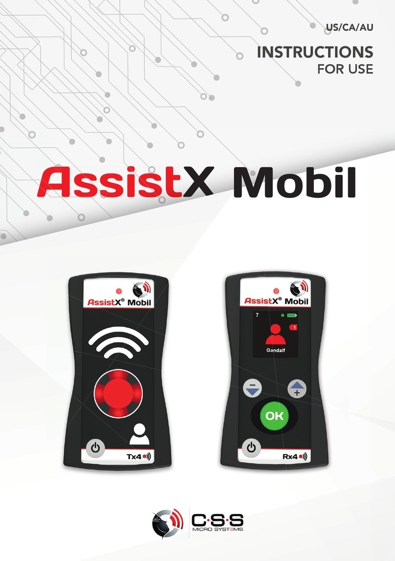
AssistX® Mobil
Features
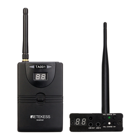
AssistX® Mobil is a mobile call system for one or more users. The set consists of a transmitter and a
receiver. To trigger a call different switches and sensors can be used.
Beside the common switches and sensors with normally cosed (NO) or normally open (NO) contact, all
active sensors of the AssistX family can be used: AssistX® AS one acoustic sensor, AssistX® ProX2
pro imity sensor, AssistX® IR one infrared sensor or AssistX® RX one radio receiver.
Transmitter:
Connections:
•AssistX® Port (pink) for many common
sensors/switches (jack plug 3.5mm / 1/8”)
Connect Sensor/Switch:
•Plug in the sensor at pace to avoid misidentification
Unplug Sensor/Switch:
•For safety reason a call is triggered whenever the sensor is plugged off. To avoid triggering a call,
switch off the transmitter before disconnecting the sensor.
USB-Socket
•Power supply, battery charge
AssistX Mobil Quick Guide 1.4 ENG Vers.1.4
Min. distance 50 cm (20“) !!
1
5
5
3
4
2
4
8676
6
1LED
2Call Button
3Confirm/OK-Button
4ON-OFF-Button
5Menu- up/down
USB socket
7Output socket
8AssistX® Port -
Sensor-/Switchport
Transmitter Receiver
8
8
9
Cornfirmation Light
9
10
10
10 Reset (restart)

AssistX® Mobil
Receiver:
Connections:
Output jack:
Plug for output jack Pin assignment Relay Mode
Menu: Settings – Alarm Signal
Access to the switch contacts
Common contact
Normally open contact (NO)
Normally closed contact (NC)
P ma : 24V/500mA
▬▬▬▬
Switched as
long as sensor
is activated
▬▬▬▬
1s impulse
▬ ▬ ▬
1s switched
3s pause
Displayelemente:
•Power supply: Charger connected to the USB port
•Battery: Power supply connected: Charging active / finished
Battery mode: Charge condition of battery
•Users: Number of connected transmitters (patients)
•Call Queue: Number of active calls in the queue (including actual call)
•Alarm: Shows Call and the name of the transmitter (patient)
•Out o range warning: Transmitter number X is out of range
Charging:
•Plug the USB power supply into the USB-socket
•LED-colour changes from green to yellow
•LED-colour changes to green after the battery is completely charged
Transmitter / Receiver Battery operation Mains operation (Charging)
LED ▬ ▬ ▬ Charge state ▬Charging
▬Finished
Call triggering and acknowledgement
Call triggering:
◦Press call button
or
◦Activate connected switch/sensor
or
◦Plug off connected switch/sensor
Confirmation:
•Press receiver´s green OK- button
Receiver: Alarm signalling stops, LED shows bright green
AssistX Mobil Quick Guide 1.4 ENG Vers.1.4
1 s
2
8
8
Power Supply
Users
Out of Range
Warning
Battery
Call Queue
Alarm
Transmitter Name
Time & Date

AssistX® Mobil
Transmitter: LED and confirmation light up bright green
•Quit call by pressing the red call button on transmitter
Receiver: green LED dims back to normal lightness
Transmitter: green LED dims back to normal lightness, confirmation light turns off
Reassurance indicator lights up red, as soon as the receiver has acknowledged the call. automatically.
Call sequence:
◦Transmitter: Press red call button – confirmation light will light up on reception of
receivers acknowledge (via automatically radio transmission)
Receiver: Selected alarm signals starts
◦Receiver: Incoming call confirmed (OK button pressed)
ransmitter: Confirmation lights changes to green
◦Transmitter: Press call button to quit and finally close the call sequence
Functions and settings
o enter and control the Setup Menu:
◦Press OK-Button 3 seconds to enter the menu
◦Menu will appear in the display.
◦Use the „+“ and „-„ buttons to navigate through the menu.
◦To e it the Setup Menu: Use function „E it“ in the menu or press the ON/OFF button.
◦I the Receiver is in the Setup Menu mode and is receiving a call, the Setup menu will be
exit automatically. Changes will not be saved in this situation.
◦As long as there are active calls, it is not possible to enter the Setup Menu.
each in new transmitters/patients:
◦Quick:
▪Press the ‚+‘ button at the receiver: The LED will light up purple.
▪Hold the key ‚+‘ for 1 second until the display shows the message „Press Call Button“
▪Now press the red call button at the transmitter you want to teach in.
▪Receiver will confirm the new transmitter with „Subscriber added“.
▪If the transmitter already in the subscriber list, the display will show the message „Subscriber
already exists“.
◦Using the Setup Menu:
▪Menu → Subscribers → Add
Delete of transmitters/patients:
◦To delete a single transmitter:
▪Menu → Subscribers → Delete
You will see the list of subscribers, go to the subscriber you want to delete and confirm by
pressing „OK“.
If you delete a subscriber having a standard name like „Patient 4“, the remaining list will be
shrinked. means: „Patient 3“ will be followed by „Patient 5“. A new transmitter will have the
name „Patient 4“
◦To delete all transmitters:
▪Menu → Subscribers → Delete All
You will see the message „Con irm: Delete all?“. if you press now „OK“ all subscribers will be
deleted. Every other key will cancel the action.
Set date & time:
◦Menu→Settings→Clock→Clock Set. Now you can adjust hours, minutes, year, month and day.
▪Use ‚+‘ and ‚-‘: to change time/date
▪Use ‚OK‘ to go to the ne t point
▪Notice: the actual week day will be showed and automatically adjusted.
AssistX Mobil Quick Guide 1.4 ENG Vers.1.4
9

AssistX® Mobil
▪With the last ‚OK‘ the time settings will be saved. You are now back in the menu.
Out of Range Monitoring:
◦The Out of Range Monitoring function monitors permanently if all
connected transmitters a reachable. Is one or are more than one
transmitters out of range, an alarm will be activated:
▪The symbol (see right) will appear on the display and is blinking.
▪The symbol shows the number of transmitters out of range.
▪An alarm sound will remind every 20 seconds.
▪If the transmitter is back in range, the warning will be deleted automatically.
▪The warning can be deleted by pressing „OK“ but will be activated again automatically after
1 minute.
Power save mode:
◦if the Power save mode is switched on (‚Menu→Settings→PowerSave‘) the display will switch off
after 20 seconds after the last key press. By pressing the „OK“ button the display will switch on
again.
◦If there is an alarm or out of range warning the display will switch on and will stay on as long as
there is an alarm or warning.
Call Queue:
◦If there is more than one alarm/call the call will be put in a queue. Means:
▪The calling transmitter will be stored.
▪The number of actual calls/alarms will be increased.
▪As soon as the actual call is confirmed by the patient
the ne t call will be served. The alarm will be activated and the name of the calling patient
will be showed.
Languages:
◦Choose your language for the menu te ts and messages on the display. Choose from English,
French and German by going to Menu→Languages
Info menu:
▪Here you can see the main information of the device like firmware version and frequency.
Battery condition:
◦The charging condition of the battery will be showed by the color of the LED (Green-Yellow-
Red). In the lower red range there will be an acoustic warning every two minutes. Beginning with
the first signal, the battery lifetime will be appro imately 1 hour.
◦If the condition of the battery is critical, the device will switch off and there will be 3 acoustic
signals. The device cannot switched on again and needs to be charged.
Before switching off there will be the following actions:
▪Transmitter: The transmitter will activate a call/alarm and waits until the call is confirmed.
After that it will switch off.
▪Receiver: Before switching off, all active calls have to be served and have to be
confirmed.
Alarm signals of the receiver:
◦The receiver is able to emit four different alarm signals::
▪Sound
▪Flash
▪Vibration
▪Relay (switch, toggle)
◦These can be switched on and off separately in the menu ‚Settings → Alarm Signals.
◦The switch output can activate e. g. e ternal call signals. It is connected to the black output
connector.
Through the menu ‚Relay Mode‘ the switch mode can be set up:
▪‚Single 1sec‘: Output switches on for one second.
▪‚Continuous‘: Output is switched on until the call is confirmed.
AssistX Mobil Quick Guide 1.4 ENG Vers.1.4

AssistX® Mobil
▪‚Interval‘: Output is switched on for one second, switched off for one second and so
on until the call is confirmed.
Alarm types and messages:
◦The receiver is able to send 3 different types of alarms:
Alarm by sensor or switch, disconnecting alarm and battery warning. The type of alarm will be
represented by the color of the inner circle of the alarm symbol:
▪ Switch/sensor alarm red: Alarm was activated by pressing the red key on the transmitter
or activating by an e ternal switch or sensor.
▪ Disconnecting alarm yellow: Alarm was activated by a problem of the e ternal sensor,
disconnecting a switch or brake of the cable or other defect.
▪ Battery alarm white: Alarm was activated because of low battery of the transmitter.
AssistX Mobil Quick Guide 1.4 ENG Vers.1.4
Alarm type

AssistX® Mobil
Firmware update:
▪AssistX Mobil transmitter and receiver are controlled by a microcontroller. The software of
the microcontroller (‚firmware‘) can be updated easily to include new features and
corrections.
It’s important to have all receivers and transmitters updated at the same time.
You can download a software called AssistX Mobil Configurator for your Windows PC at www.csslabs.de.
This software makes it easy to update your AssistX Mobil. The following steps are needes to be done:
•Download the software at www.csslabs.de (→Downloads) and install it on your PC.
•Start the software.
•Switch on your AssistX Mobil and connect it using the USB cable to your PC. If
needed drivers will be installed automatically. Depending on the Windows version it can
take a few minutes. Take care of the symbol in the task bar:
•Wait until driver installation is done:
•If the drivers are installed the device will be recognized automatically by the
Configurator.
•From version V1.17 on AssistX Mobil doesn’t need to be switched on.
•If the device is not recognized automatically, plug off and on again.
•As soon as the AssistX Mobil Configurator recognized the device it will check
automatically which version of the firmware is installed and shows the version. If there is
a newer version available the Configurator shows a message:
Click now on „Update AssistX Mobil“. The update window will open.
Click “Start update” and wait until the process is completed.
AssistX Mobil Quick Guide 1.4 ENG Vers.1.4

AssistX® Mobil
Directions
Call systems AssistX Mobil meets the requirements of VDE 0834 for call systems
Cleaning The device may be damp cleaned using a mild detergent. Don´t dip into water!
Save the environment!
This electronic device contains recyclable materials and must not be disposed off with the
household waste. (2002/96/EC) When you dispose off this device, hand it in at a collection
point for electronic devices You can get information on collection points in your region from the
local authorities.
Con ormity
This product conforms to CE.
This products meets the requirements of DIN VDE 0834 for call systems
Technical data
Power supply 5V/500mA DC, USB power supply, Lithium Polymer battery
Connections Transmitter: pink sensor/switch jack (3.5 mm (1/8“) - AssistX Port )
Receiver output jack: Normally closed (NC) normally open (NO) contact
ma . 24V/100mA
Radio frequency 869,3 MHz (Social Alarm)
Range open area up to 200 meters, inside buildings up to 30 meters
Battery life time Transmitter 50 h (without Pro imity Switch), 20 h (with Pro imity Switch)
Battery life time Receiver Display on: 15 h, power save mode: 30 h
CSS Microsystems GmbH
In den Hofäckern 16
D- 74189 Weinsberg
WEEE DE94635635
www.css-microsystems.de
AssistX Mobil Quick Guide 1.4 ENG Vers.1.4
Patent: DE 102015013572
Other manuals for AssistX IR one
1
This manual suits for next models
4
Table of contents
Other CSS Transmitter manuals
