manuals.online logo
Brands
  1. Home
  2. •
  3. Brands
  4. •
  5. ENSIM SENSORS
  6. •
  7. Transmitter
  8. •
  9. ENSIM SENSORS DX-ELS-tx User manual

ENSIM SENSORS DX-ELS-tx User manual

OPERATING
MANUEL
LEVEL TRANSMITTERS
DX-ELS-tx
Model :
Model: 01-2023-009
Information in this manual is reviewed and completely reliable. Responsibility is not assumed due to any typing error.
Products in this manual are available only for information purpose and they may be changed without notice.
1
Models:
DX-ELS-tx
Important Notes:
Used Symbols :
Table of Contents :
: Caution : Note : Disposal
Please read this manual carefully before installation of the level transmitter. User is responsible for accidents and losses arising
from failure to comply with the warnings in this manual.
In the event that level transmitter is broken, take measures in order to prevent accidents and losses which can occur in its system.
There is not any fuse and circuit breaker on the instrument; they should have been added to the system by the user.
This manual should be stored in an easily accessible place for subsequent use.
The manufacturer's liability cannot exceed the purchase price of the device according to the law.
Do not make any modification on the instrument and do not try to repair it. Reparation should be made by authorized service staff.
Do not operate the system before making assembly in compliance with the assembly chart related to the instrument.
Products which do not contain label and serial number are considered to be excluded from the warranty scope.
The instrument's useful life, determined and announced by the ministry, is 10 years.
General Information...........................................................................................................................................................................2
Installation .........................................................................................................................................................................................7
Failure Detection..............................................................................................................................................................................18
Disassembly of Instrument ............................................................................................................................................................18
Service .............................................................................................................................................................................................18
Recalibration....................................................................................................................................................................................18
Repair................................................................................................................................................................................................18
Disposal ...........................................................................................................................................................................................18
Terms of Warranty ..........................................................................................................................................................................18
Terms of Return ................................................18
1.
2.
3.
4.
5.
6.
7.
8.
9.
10.
2
1. General Information :
1.1. Material Acceptance
Check that there is no damage on the packages during the transportation immediately after the material acceptance. If packages are
damaged, open the packages immediately and check whether products are affected or not, if there is any damage, send your
complaint report to the transporter company and its photocopy to the address of our company.
1.2. Information about Areas of Use
Level Transmitter is designed for industrial plants. It should never be used in mines.
Otherwise, the responsibility of the manufacturer is eliminated.
Tank level measurement and control,boiler kontrol,store room control..
Ambient Conditions: Relative Humidity: 0-98 % RH Ambient temperature: 60 °C (It is not used under -20 °C)
1.3. Working Principle
DX-ELS-tx level transmitter are used for tank levels and for controls. In the float when the magnet magnetic area moves according to the
liquid in the tube, then the reed swicthes the electrical circuit on or off when it reaches the level of the sensor.Reed swicthes in and out.
The changes of the reed sensors with alarm or a level information can be assessable with a relay circuit or a control device.Sensitivity increases
according to reed sensor lowering range.The advantages of providing the analog output in the enclosure are preferred by the users.
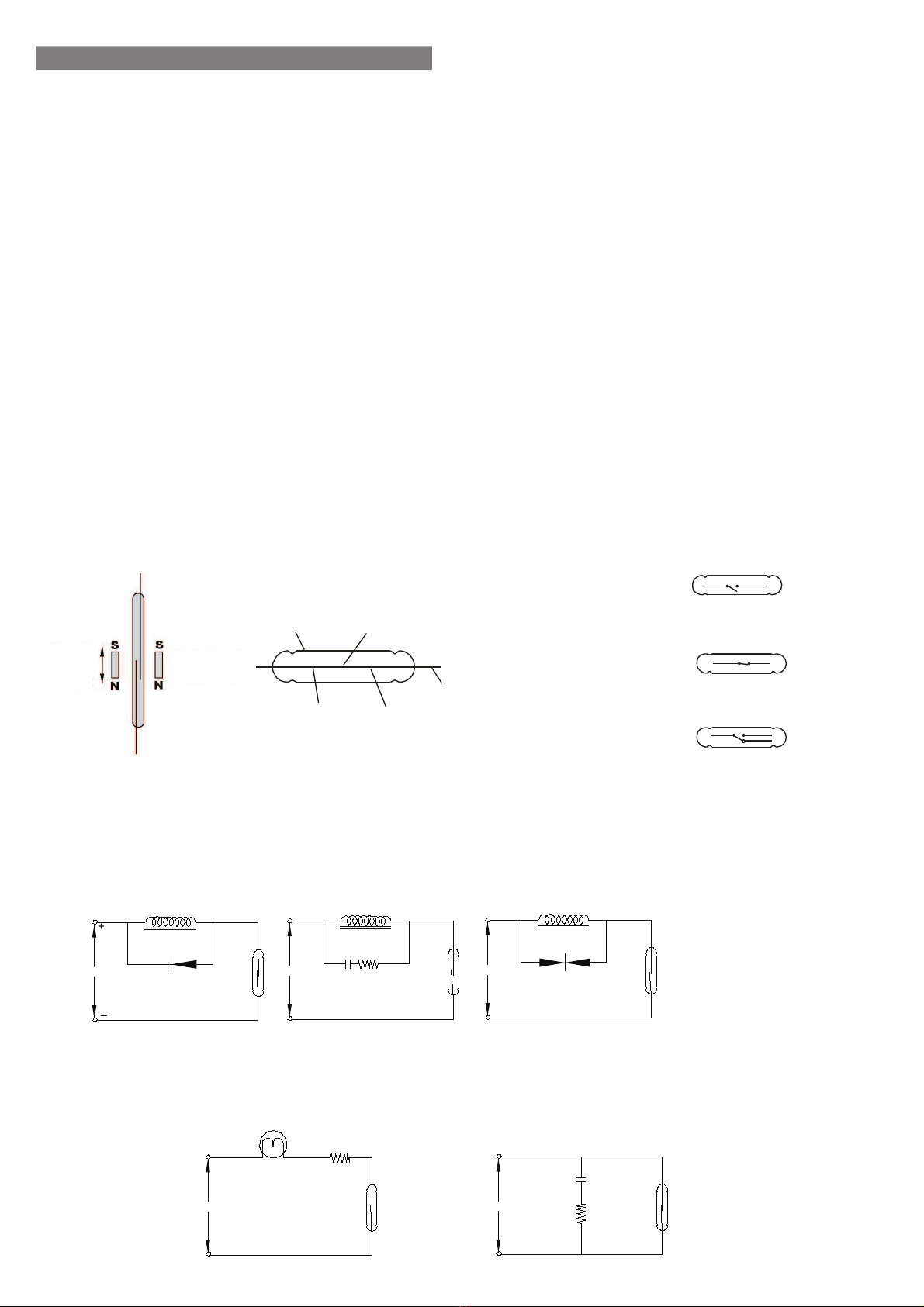
1.4. Reed Relay and Operation Conditions
Advantages:
*A variety of materials according to the flow
*Different choices of ignition
*Quick delivery
*Different types of technics
Glass Tube Contact
Inert Gas Magnetic Reed
Wire
Magnet
Closed
Open
SPST-NO
Single Pole-Single Throw
Normally Open
SPST-NC
Single Pole-Single Throw
Normally Closed
SPDT-NO/NC
Single Pole-Double Throw
Open / Closed Contact
Inductive Load
Capacitive Load
When reed switch is used for loads such as electromagnetic relay ,contactor or solenoid, reed switch may be exposed to very high
voltage depending on value of inductive load. This causes either failure of switch or shortening its service life. Therefore, it is
recommended to be used as follows depending on used voltage, for the purpose of protection of switch.
When reed switch is used with capacitive load, it may cause that high current passes over reed switch, depending on value of
capacity during Charge '96 Discharge of capacity. So this may cause failure of switch. It is recommended to be used as follows
depending on used voltage, for the purpose of protection of switch.
Inductive Load Inductive Load Inductive Load
Diod
DC AC AC
C R Varistor
Neon Lamp
AC
R
AC
C
R
3
1.5. Technical Specifications
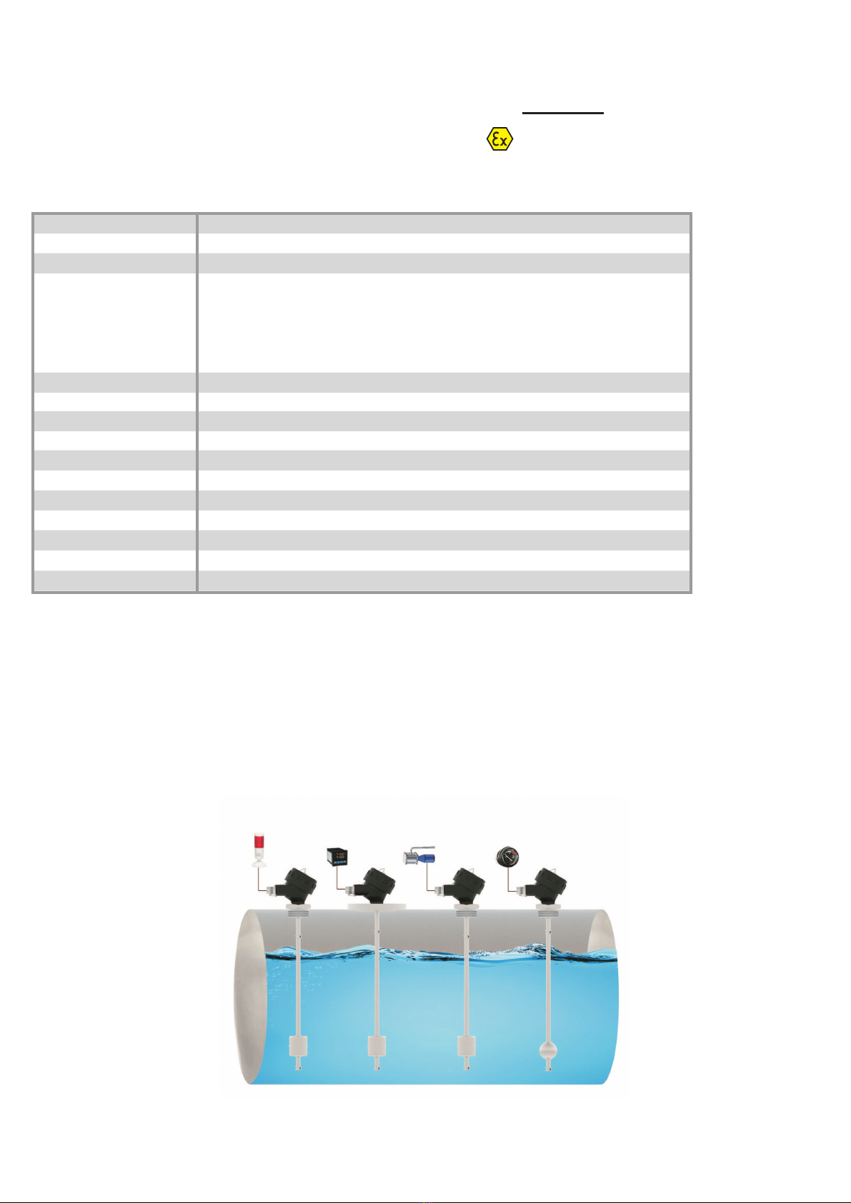
Example of application :
Certification
*
DigitalDisplay PLC Analogue IndicatorLight
DX-ELS-tx
Max. 125 °C
0-98 % Rh (Non-condensing)
(-) 20 °C ... (+) 60 °C
304 St.st. (Std.) Opt. 316 St.st. , Aluminum
Aluminium Injection Molding- AlSi12Fe (Std)
Black (RAL 9005)
316 St.st. (Std.) Opt. PU , PP
304 St.st. (Std.) Opt. 316 St.St. , Brass
2" BSP (Std.) Opt.Selectable from Table.
S40A (Std.) , Selectable from Table.
1 ( Std.) A large number of available.
Max. 2500 mm (Thread Included)
Terminals
M20 x 1,5 (Std)
4-20 mA Std. Two Wire Opt. 4-20mA , 0-20mA , 0-10V Three Wire, Ohm
Std. 15 mm / 10 mm / 5 mm / 1 mm
12...32 VDC
IP 66 / 68 (EN60529)
CE Declaration , EMC , LVD , ATEX
Working Temperature
(Tp)
Ambient Humidity
Ambient Temperature (Ta)
Material Connection
Housing
Float
Pipe
Connection
Float Type
Number of Float
Stem Length
Electrical Connection
Cable and Plug Entry
Output
Fequency of Detection
Supply Voltage
Protection Class
Certifications and Approvals
ll 1/2G Ex db ia llC T6...T2 Ga/Gb For Gas
ll 1/2D Ex tb ia lllC T85°C...T300°C Da/Db For Dust
Have a look at the temperature class chart.
4
1.6. Label Information :
1.7. Package and package contents :
Please check whether you have taken delivery
of below listed content completely or not and check
its conformity with criterions in your order:
*Float Level Transmitters
*This operating manual
Box
Label
Type
Level
Transmitteri
S.N.
Quantity
DX-ELS-tx 025-00-009-02-12-02-500-113-19-10/0
IE18030050-0008
:
:
1 pc.:
Serial Number
Model
Piece Barcode
Kullaným Kýlavuzu Montajdan Önce Okunmalýdýr.
Supply 24VDC ±%10:
IE18030050-0008
Supply Voltage
Explosive ProtectionAreaProduct Name
Std. Package
Product
Label
LEVEL SWITCH
MADE IN TURKIYE
www.ensim.com.tr
Serial Number
Notified
Date Sign
Explosive ProtectionArea
Product Name
Producer Website
Warning Symbols
Working Conditions
Manufacturer Brand
Type : DX-ELS-tx 025-00-009-02-12-02-500-113-19-10/0
Power Supply
Output
Process Temp. / Press.
T (Ambient)
Serial Number
24VDC +/- %10
4-20mA Two Wire
: Max. 125°C / Max. 30 bar
-20...+60°C
IE18030050-0008
DO NOT OPEN WHEN ENERGIZED
KEEP TIGHT WHEN CIRCUIT ALIVE
Product
Label
Ground
Label
Cable Plug
(Suitable Cable Diameter : Ø 6-12 mm)
Aluminium Housing
Grounding Terminal
(Max.1,5 mm²)
Recommended Cable
(5x1,5 mm²)
Bund
Stops
Metal
Label
IE 18 03 0095 - 0014
If the ATEX certificate metal label is damaged, you can contact
the manufacturer with the serial number.
Note :
Metal
Label
LONCA A.Þ. Ferhatpaþa Mah.Gazipaþa Cad. No:104A
34888 Ataþehir - ÝSTANBUL / TÜRKÝYE
IEP23ATEX1210X
ll 1/2G Ex db ia llC T6...T2 Ga/Gb
ll 1/2D Ex tb ia lllC T85°C...T300°C Da/Db
Type B22x
www.ensim.com.tr
16A 240 VAC 50 / 60 Hz IE18030095-0014
S.No:
Manufacturer Name ManufacturerAddress
Model Housing
Serial
Number
Housing Features
Explosive Protection
Area ATEX Classes
Product
Number
System
Number
Month
Year
Work
Order
1.10. Safety Ýnstructions (ATEX)
Safety instructions should be read and applied to the end.
-The following notes must be taken into attention to protect the operator and the enviroment from possible hazards.
-The device setup and maintenance of this device must be done by knowledgeable persons who has read the instructions and is familiar with
the safety at work.
-Ýt should be checked by the users that the products are fitted suitable to the zone maps.
-Work safety,must be observe by accident prevention regulations and national installation standards.
-The product should be used within the specification presented guideline.
-You can only mount the device when there is no presure.
-These safety instructions are protected in terms of 1 / 2 D and 1 / 1 G category for DX-ELS-tx coded series and is compatible with
IEP23ATEX1210X and CE certificate.
-The Label should be used in appropriate environments.
-Because the enviroment is max. 60 °C you should choose a suitable cable for use.
-Do not over tighten the cable gland in order not to affect the IP protection class.
-Make sure the cable entry and plug is tightened right.
-Ground connection must be done properly and checked without energizing.
-Before starting use make sure the lid is fully closed and the set screw is tightened.
-DX-ELS-tx models are metal protected.Ýt is Compatible with different supply voltages specified in the catalog.
- The metal enclosure must be in the 2D or 2G zone. The pipe and float section must be located in the 1D and 1G zone.
-Max. working temperature,max. Surface temperature can change depending on the model, Please read the document carefully before using.
-During the mounting it should be checked that there is no mechanical stress or deformation in the tank wall.When this happens, the sensor should
not be energized without the necessary correction measures.
-Check that the presure in the tank hasnt exceed the presure shown in the catalog.
-The mounting sensor must be mount properly in the tank filling system.In case it is not suitable, the sensor must be protected and the in-tank
apparatus must be protected.
- Flange surface smoothness must be maintained in flanged connection.
- Flange seating surface should not be scratched, and suitable liquid gasket should be used instead of sealing with gasket in counter flange mounting.
- Flanged connections are welded with the sensor part.
-The sensor is designed to withstand the chemical effects of the materials.Check the suitability of different materials.
-The Sensors are in suitable storage conditions and protected from dust and damp.
-Device repairs should only be done at the manufacturer Lonca Inc.
-Protect the device from friction and cleaning should be done without water.
-In case of improper circuit conditions, the main energy must be completely disconnected and safety measures should be taken without replacing
the temperature circuit breaker with its backup.Changes should be made in a safe area.
5
1.8. Target Group
This operating manual has been prepared for qualified technical personnel.
1.9. Certifications and Approvals
:It shows that, product meets required conditions of EU with CE stamp
and stipulate that product passed quality assessment stages
All the features and tests on this decument has manufactured with DX-ELS-tx models at LONCA Inc.
Note:
TS EN 61326 - 1 : 2021EMC (2014 / 108 / AT) :
TS EN IEC 60079 - 0 : 2018
TS EN 60079 - 1 : 2014
TS EN 60079 - 11 : 2012
TS EN 60079 - 31 : 2014
ATEX (2014 / 34 / AB) :
LVD (2014 / 35 / AB) : TS EN 60204 -1 : 2018
TS 3033 EN 60529 : 2014
6
1.11. ATEX Marking Sample Description
II 1/2 D Ex (ta/tb) ia IIIC T4 IP66
II 1/2 G Ex d ia IIC T4 IP66
Dust
Explosive Protection
Area
Equipment Group
Equipment Category
Explosive Atmosphere
Explosive Protection
Protection Type
Dust Type
Temperature Class
(Max. Surface Temperature)
Housing Protection Class
Gas
Explosive Atmosphere
Protection Type
Temperature Class
(Max. Surface Temperature)
Housign Protection Class
Equipment Group
Equipment Category
Explosive Protection
Gass Type
Explosive Protection
Area
2. Installation :
7
2.1. General Notes :
The device installation is in 2014 / 34 / EU criteria to ensure the safety of atmosphere and people from explosions, must only be done by staff who
knows the safeguards.
Do not apply force to the instrument during the installation!
Do not use the Level transmitter with a greater pressure than recommended pressure.
Do not forget that instrument is precise, carry it carefully and prevent not to be damaged.
It should be guaranteed that there are not any magnetic particles.
The Max. working pesure should not be exceeded.
2.2. General Installation Stages
*Remove Level transmitter from the box carefully
*Check whether gasket is appropriate for fluid or not. If is not appropriate, contact with the producer.
*Then, apply below mentioned explanations according to structure of the design.
2.3. Special Notes
*Please ensure that there is no mechanical stress on the shaft following installation. Such case will cause slipping in thecharacteristic curve.
*Level transmitters must be placed upright or horizontal.
*Allocate valve certainly in the process connection while instrument is used.
*Allocate blowdown valve under bottom flange for blowdown.
*If instrument is mounted outside and if there is any danger of lightning or
excessive pressure, take preventive measures by taking necessary measures.
*In the operating conditions, level transmitter may be hot according
to situation of fluid, in this case, do not touch the indicator, otherwise your skin is damaged.
*The grounding product must be done properly. (can be done outside or in housing)
2.4. Installation For Mechanical Connections
*Use appropriate O-Ring or gasket for tightness.
*Ensure that its surface is clean and smooth.
*Assemble the instrument manually.
*Connect the contacts as shown in the figure.
(For G1" max. 20 Nm, G 1 1/4, for G 1 1/2 max. 30Nm)
2.5. Mechanic Connections :
Order
Code
Dimension
B
Hex
[mm]
Stem Lenght
b [mm]
3/8BSP
1/2BSP
3/4BSP
1BSP
1 1/4BSP
1 1/2BSP
2BSP
50
50
50
50
50
60
70
20
14
14
23
23
23
23
(ISO228-1)
0003
0004
0005
0006
0008
0009
0012
PN 16 D (mm)
DN25
DN32
DN50
DN80
DN100
165
140
165
200
220
85
100
125
160
180
D1 (mm) b (mm)
16
16
18
20
20
(ISO1092-1)Order
Code
0502
0503
0505
0507
0508
PN 40 D (mm)
DN25
DN32
DN50
DN80
DN100
115
140
165
200
235
85
100
125
160
190
(ISO1092-1)
D1 (mm) b (mm)
18
20
20
20
24
Order
Code
0702
0703
0705
0707
0708
150 LBS D (mm)
DN50
DN65
DN80
DN100
152,4
177,8
190,5
228,6
121
139,7
152,4
157,2
(ANSI B16.5)
D1 (mm) b (mm)
19
22,2
23,8
23,8
Order
Code
1005
1006
1007
1008
Dimension Dia. b
(mm)
DN32
DN50
DN65
50,5
64
91
15
17
17
(ISO2852)
D (mm)
1501
1502
1503
Order
Code
D (mm)
DN40
DN50
DN100
56
68
121
48
61
114
d1 (mm) A (mm)
13
14
20
Dimension
DN40
DN50
DN100
Dimension
1600
1601
1602
Order
Code
b
D1
D
AA
B
b
b
D
D
d
d1
A
Thread (Connection has been welded with sensor)
Flanged (Connection has been welded with sensor)
Clamp (Connection has been welded with sensor)
Dairy
(Connection has been welded with sensor)
8
2.6. Example Mounting Types :
Reed Relay
Resistance
Magnet
RTD COM
Float
Protection Case :
Material : 304 Stainless Steel
Welded manufacturing
Opens - Closes Hinged
To Protect Against external conditions.
Housing :
EU-Type Examination Certificate Number : TSE 22ATEX 0175U
The marking of the equipment :
II 2G Ex d IIC Gb
II 2D Ex tb IIIC
Cover Seal : NBR Nitrile Rubber 120 °C, Opt. FPM (Viton) 200 °C)
MATERIAL PROTECTION
CLASS
TEMPERATURE
(oC)
TYPE
B21x IP 66 /68 (-) 40...(+) 200
SIZE
a x b (mm)
132 x 104
ORDER
CODE
704
B22x Aluminium IP 66 /68 (-) 40...(+) 200 117 x 102750
Aluminium
Alüminium
B22x
b
a
Alüminium
B21x
b
a
Ta
Factory Area
(Safe)
ZONE 21 / 1
or
ZONE 22 / 2
Tp
Process Side
(Explosive Enviroment)
ZONE 20 / 0
or
ZONE 21 / 1
or
ZONE 22 / 2
9
2.7. Part Names
Cover Seal
Electronic Card
Product Label
Body
Grounding Label
Metal Label
Pipe
Float
O-Ring
Reed Relay
Chain
Cover
Cover Set screw
Body Set screw Cable RecordStopper
Thread
Connection Thread
Thimbile
Float
Pipe Plug
Product Label
Electronic Card
Cover
Cover Seal
Chain
Metal Label
Cable Record
Grounding Bracket
Rivet
Body
Grounding Label
Connection Thread
Thread
Reed Relay
Float
Thimbile
Pipe Plug
Pipe
Grounding Screw
Grounding Outer Bracket
Body
Set screw Cable RecordStopper
10
2.8. Electrical Installation
Make the electrical connection of the instrument according to details on its label, table and cable figures in this manual
4-20mA
Two Wire
4-20mA
Three Wire
0-10V
Three Wire Ohm
Supply
Output
Supply
Output
Supply / Output
mA
Load Supply
Output
Note: The IPC A 600 is manufactured in accordance with class 2 requirments. HALS (Unleaded) surface treatment applied.
For B22x
4-20mA Two Wire
DX
LINK
1
2
3
4
5
1
2
3
4
5
Output
mA
4-20mA Three Wire
DX
LINK
1
2
3
4
5
1
2
3
4
5
0-20mA Three Wire
DX
LINK
1
2
3
4
5
1
2
3
4
5
0-10V Three Wire
DX
LINK
1
2
3
4
5
1
2
3
4
5
Supply Output Supply Output Supply Output
Load
4-20mA
Three Wire
0-20mA
Three Wire
4-20mA
Two Wire
For B22x
1
6
5
43
2
(+)(-)
Sensor Input
V(+) V(-)
1-5V
Three Wire
1
6
5
43
2
V(+)
(+)(-)
V(-)
500
W
0-10V
Three Wire
1
6
5
43
2
V(+)
(+)(-)
V(-)
250
W
V(-)
1
6
5
43
2
V(+)
(+)(-)
V(-)
Output(+)
Load
Output(+) Output(+)
Sensor Input Sensor Input Sensor Input
For B21x
11
12
11
14
13
Input Signals
44
43
42
41
Channel 1
-
+
Current
2 Wire
Transmitter
HART
Power Rail
-
+
mA
mA
-
+mA
mA
Passive 2 wire
+
Status relay signal
Rail, supply (+)
Rail, supply (-)
No connection
No connection
Tx
54
53
52
51
-
+
Current
2 Wire
Transmitter
HART
Tx
31
32
33
34
Power connection:
Supply (-)
Supply (+) 19,2...31,2 VDC
Device Status
NC
Device Status
Output Signals
Channel 2
HARTHART
Channel 2
Zone 0,1,2
20,21,22,M1 &
CI. I/II/III, Div. 1
gr. A-G
Zone 2 & CI. 1,
Div. 2, gr. A-D
or Safe Area
Same power rail as above
12
2.9. Float Types
Z
X
Y
G
S2A / S5A / S6A
S40A / S41A / S53A
X
Y
Z
G
S42A / S52A
X
G
Y
Z
S1Y / S1A / S7A / S17A
S10Y / S11A / S54A
Float :
X
Y
Z
G
P3 / P6 / P7 P9
Minimum
Distances
Type Material X Y Z A B
Dia.
of Pipe
Max.
Press. Density C
Max.
Temp.
S2A
S5A
S6A
S7A
S17A
S40A
S41A
S42A
S52A
S53A
S54A
316 St.St.
316 St.St.
316 St.St.
316 St.St.
316 St.St.
316 St.St.
316 St.St.
316 St.St.
316 St.St.
316L St.St.
316L St.St.
43
73
73
43
52
55
55
55
73
52,5
51
43
73
73
52
35
55
55
30
40
50,2
61,2
11
20
17
15
15
15
15
15
20
15,5
15,5
10
16
15
13
13
13
13
13
16
14
14
15
30
30
30
30
30
30
20
20
10
10
150
150
150
150
150
150
150
150
150
200
200
0.80
0.65
0.65
0.88
0.85
0.80
0,9
1,2
0,9
0,6
0,47
34
50
50
34
39
42
42
42
50
42
50
68
99
99
68
78
82
82
55
65
82
90
34
50
50
34
39
42
42
42
50
42
50
0102
0104
0105
0106
0111
0113
0114
0115
0118
0119
0120
Order
Code
Type Material X Y Z A B
Dia.
of Pipe
Max.
Press. Density C
P3
P6
P7
P9
PU
PU
PU
PP
30
35
44
46
45
42
50
44
12
15
18
17
10
13
15
15
1
1
1
5
Max.
Temp.
80
80
80
80
0.76
0.65
0.40
0.65
28
35
38
38
60
65
70
76
40
40
50
38
0201
0203
0204
0213
Order
Code
Technical Specifications :
ABCABC
Technical Specifications :
13
2.10. Sample Models
Thread Flanged
L
1 1/4
BSP
...Ohm / 20 mA / 10V / 20 mA
...Ohm / 4 mA / 0V / 0 mA
Thread
2
BSP
Thread
L
L
...Ohm / 20 mA / 10V / 20 mA
...Ohm / 4 mA / 0V / 0 mA
ØDN
L
2BSP
** Length -/+ 5 mm tolerance is available.
Sample Application :
EMPTYING FILLING
Stop
Start
Max
Min.
NC
NO
Start
Stop
Max.
Min.
NC
NO
14
2.11. Maximum Surface Temperature
Temperature Class Table
(-) 20° C < Ta Ambient < (+) 30° C...(+) 60°C Working Temperature: (-) 20°C  (+) 125°C
30 min. (-)40(+)150°C
< 80°C
< 90°C
< 125°C
60°C
60°C
60°C
Tp PROCESS TEMPERATURETa AMBIENT TEMPERATURE TEMPERATURE CLASS
T6
T5
T4
MODEL
10 min. (-)40(+)60°C
< 60°C
60°C T6
Working Temperature: (-) 20°C  (+) 60°C
MODEL
40 min. (-)40(+)200°C
Group II
Group III
(-) 20° C < Ta Ambient < (+) 30° C...(+) 60°C
Without opening the cover
standby time
Without opening the cover
standby time
Tp PROCESS TEMPERATURETa AMBIENT TEMPERATURE TEMPERATURE CLASS
DX-ELS-tx
DX-ELS-tx
15
2.12.
Order Form : Please consider sample models when coding
3CERTIFICATE
No.........................................................................0 (EN10204-3-1) Material Certification.............................1
4ELECTRICAL CONNECTION
With Terminals (For Housing Models)................00
Special.........................................................................x
6CONNECTION MATERIAL
304 Stainless Steel.......................................001
316 Stainless Steel.......................................002
Brass.............................................................003
Aluminium.........................................................005
Special.........................................................................x
7PIPE SIZE
8 mm...............................................................08
10 mm...........................................................10
12,7 mm........................................................12
12.7 mm / 13 mm.....................................................13
15 mm...................................................................15
Special.........................................................................x
1MODEL
Standard Version .............................DX-ELS-tx
2HOUSING
Aluminium Housing ,
B22x IP66 / 68.........750
Aluminium Housing ,
B21x IP66 / 68.........704
Special.........................................................................x
5CONNECTION
(Connection has been welded with sensor)
Thread 3/8 BSP........................................0003
Thread 1/2 BSP........................................0004
Thread 3/4 BSP........................................0005
Thread 1 BSP............................................0006
Thread 1 1/4 BSP......................................0008
Thread 1 1/2 BSP......................................0009
Thread 2 BSP............................................0012
Thread 1/2 BSP (Moving Type).................0112
Thread 3/8 BSP Elbow Type....................0109
Thread 1/2 BSP Elbow Type ...................0110
1/8 NPT................................................................0200
1/4 NPT................................................................0201
3/8 NPT................................................................0202
1/2 NPT................................................................0203
3/4 NPT................................................................0204
1 NPT..............................................................0205
1 1/4 NPT.............................................................0206
1 1/2 NPT.............................................................0207
2 NPT.............................................................0208
Special........................................................................x
Note: Refer to the table for others.
16
10 FLOAT MODEL
Select from Table
STEM LENGHT
.... mm
9
EXAMPLE
13 OPTIONAL
No............................................................................../ 0
External Tank (Measurement must be specified) ... / H
Test Rod .................................................................. / T
Shetter (For the outside of the tank) 304 St. St........./ K2
Float Housing......................................................... / M
Zener Baryer 9106B-BIB Single Channel.............../B1B
Zener Barier 9106B-B2B Double Channel............../B2B
Special..................................................................... / x
11 OUTPUT
3-180 Ohm..........................................................23
10-180 Ohm.........................................................24
240-33 Ohm..............................................................25
4-20 mA Two Wire HART..........................................43
Special.........................................................................x
4-20mA Two Wire.....................................................19
4-20mA Three Wire..................................................20
0-10V Three Wire.....................................................21
0-20mA Three Wire...................................................22
12 SENSITIVITY RANGE
15 mm........................................................................15
10 mm........................................................................10
5 mm........................................................................05
11mm........................................................................01
Special.........................................................................x
8PIPE MATERIAL
304 Stainless Steel....................................................001
316 Stainless Steel....................................................002
Brass.......................................................................008
Special........................................................................x
DX-ELS-tx 750 - 00 - 0012 - 002 - 13 - 001 - 1200 - S40A - 20 - 10 / 0
Note: Should be selected according to the connection
and radius.
Note: From connection thread included
DX-ELS-tx Level Transmitter, Aluminium Housing B22x, 2 BSP Male Thread, Connection and Pipe Material 316 St.St.
L = 1200mm, S40A Float, 4-20mA Three Wire Output, 10mm sensivitiy
17
2.13.
WARNING !!!
Please pay attention to following matters in order to operate your level switch properly.
Do not pull the cable strongly,
otherwise the characteristics
might be changed.
Please keep away from magnetic materials
like iron board ; otherwise the
characteristics might be affected
Please do not drop ,
otherwise the characteristics
might be changed.
Please do not dip cables
potting into liquids,otherwise
instulation problem may cause.
Do not fasten switch reversely ,
otherwise its characteristics
might be changed.
Do not connect the switch in reverse.
Their characteristics may vary.
Vibration might be
caused instability.
Do not remove the plastic parts
of the bottom of the switch body ,
do not loosen.
In case vapour splash cable
potting points,insulation
problem may cause.
Excess current , to be drawn as
a result of direct connection to motor,
may burn relay of switch
Please avoid using with liquids which
damage materials of parts ,otherwise
quality can not be maintained accurately.
Please do not mount
slant way, otherwise
switch do not work correctly.
iron board
18
3. Failure Delection
Breakdown
Fluid is leaking
The analog isn't giving
signal or it's giving the
incorrect value.
Housing or body broken
There is an Unstable
work in the signal.
The thread is stripped.
Probable cause
-Hole in the body metarial.
-The socket may not contact
-The product has been exposed in a mangetic
ambient.
-Angle of connection is not right.
-Applied voltage above the value.
-Over tightening the screws during installation
-Product falling or impact from outside.
-The product has been left in a magnetic ambient.
-The product has been exposed in a vibration.
-Product exposure in high temperature.
-Been tightend with torks more than specified
during installation.
Failure detection\correction
-Check if their working under favorable conditions ,
contact the manufacturer.
-Check the socket connections.
-The magnetic field element must be removed or isolated.
-Fix the angle of the montage.
-Report to authorized service.
-The magnetic field element must be removed or isolated.
-Vibrations must be blocked from that will effect the product or must
connect where there is no vibration.
-Use in suitable temperature.
-Report to authorized service.
If you find an error, try to eliminate it by using this table or send the instrument to our service address for repair.
The instrument should be repaired only by authorized service! Serial number shall be indicated to the authorized service center.
4. Disassembly of Instrument
Instrument should be disassembled while feeding and pressure is not available!
5. Service
6. Re-Calibration
During long period usage of level switch, there might be deviations on measurements. In those cases, recalibration is recomended. Re-calibration could be made by your
technical staff or you could send to manufacturer company. According to IEC 60017, ex proof devices must be go through detailed inspection every 3 year from purchase
date.Respobsibility of inspections are belong to the user ( IEC: International Electrotechnical Commission)
7. Repair  Manufacturer Address
If irreparable breakdowns occur, the instrument should be sent to us for repair purpose. Before this, the instrument should be cleaned carefully and packaged
so as not to be broken. Furthermore, you should also add a detailed explanation which describes the breakdown while instrument is sent. If your instrument
contacts with harmful substances, decontamination report should be also sent additionally. In the event that instrument does not have any decontamination
report or our service department has doubts about instrument, repair process will not start until an acceptable report is sent.
8. Disposal
The instrument should be disposed according to 2002/96/EC and 2003/108/EC European Directives (waste electrical and electronic instruments).
Waste electrical and electronic equipment should not be mixed with domestic wastes!
If the instrument has contacted with harmful substances, special attention should be paid for its disposal!
9. Terms of Warranty
The instrument has warranty legally for 24 months after delivery date. Warranty demands are not accepted in case of inappropriate operation, damage on the
instrument or any modification on the instrument.
10. Terms of Return
In the return of materials, user should send an open list related to damage or problem, malfunction of the material to be returned or its operation in the different
modification, with the instrument. If it is required to return the material, used in the dangerous, corrosive or toxic fluid, in this case, used part should be cleaned
very carefully. Security of personnel should be ensured. All products to be returned should be sent to our company address, which
we have stated.
The instrument does not require maintenance. If it is desired, residue accumulated inside should be blown according to kind of fluid and instrument can be cleaned
with soft cleaning solutions. Measures should be taken during the disassembly.
If the instrument contacts with hazardous substances, necessary measures should be taken for decontamination!
Service -Manufacturer Company Name and Address:
LONCA MAK. SAN. TÝC. A.Þ.Ferhatpaþa Mah. Gazipaþa Cad. No:104A - P.K. 34888 Ataþehir - ÝSTANBUL - TÜRKÝYE
Phone:+90 216 50 50 555 Pbx - Fax:+90 216 515 45 84 E-Mail: [email protected] Web: www.ensim.com.tr

Other manuals for DX-ELS-tx

1

Other ENSIM SENSORS Transmitter manuals

ENSIM SENSORS DX-ELS-tx User manual

ENSIM SENSORS

ENSIM SENSORS DX-ELS-tx User manual

ENSIM SENSORS EGW Series User manual

ENSIM SENSORS

ENSIM SENSORS EGW Series User manual

ENSIM SENSORS DX-ECAP User manual

ENSIM SENSORS

ENSIM SENSORS DX-ECAP User manual

ENSIM SENSORS ECAP 101 User manual

ENSIM SENSORS

ENSIM SENSORS ECAP 101 User manual

Popular Transmitter manuals by other brands

Mun Ah Plastic Electronic Toys CTX-1710 manual

Mun Ah Plastic Electronic Toys

Mun Ah Plastic Electronic Toys CTX-1710 manual

M-system M3LM instruction manual

M-system

M-system M3LM instruction manual

Presys TY-2090 Technical manual

Presys

Presys TY-2090 Technical manual

EUTECH INSTRUMENTS 2-WIRE CONDUCTIVITY TRANSMITTER operating instructions

EUTECH INSTRUMENTS

EUTECH INSTRUMENTS 2-WIRE CONDUCTIVITY TRANSMITTER operating instructions

M-system M6SVS instruction manual

M-system

M-system M6SVS instruction manual

RKI Instruments 65-2335RK Operator's manual

RKI Instruments

RKI Instruments 65-2335RK Operator's manual

Emerson Rosemount MultiVariable 3051SMV Reference manual

Emerson

Emerson Rosemount MultiVariable 3051SMV Reference manual

HBC-Radiomatic micron 5-3 operating instructions

HBC-Radiomatic

HBC-Radiomatic micron 5-3 operating instructions

GLI International PRO-E3 series operating manual

GLI International

GLI International PRO-E3 series operating manual

M-system W2TS instruction manual

M-system

M-system W2TS instruction manual

Endress+Hauser CM14 operating instructions

Endress+Hauser

Endress+Hauser CM14 operating instructions

Salcom 11-22-0000 Operator's manual

Salcom

Salcom 11-22-0000 Operator's manual

Ditel KOS206TC user guide

Ditel

Ditel KOS206TC user guide

Primex XR Operation manual

Primex

Primex XR Operation manual

Vimar LINEA manual

Vimar

Vimar LINEA manual

Acromag DT236-0600 user manual

Acromag

Acromag DT236-0600 user manual

AMERITECH AM5 instruction manual

AMERITECH

AMERITECH AM5 instruction manual

Chiayo SM-6100 IrDA Operation manual

Chiayo

Chiayo SM-6100 IrDA Operation manual

manuals.online logo
manuals.online logoBrands
  • About & Mission
  • Contact us
  • Privacy Policy
  • Terms and Conditions

Copyright 2025 Manuals.Online. All Rights Reserved.