No liability is accepted for any misprints. We reserve the right to make design changes.
For your own reference
Fill in the information below. It may come in useful if anything should happen.
Product: Serial number:
Installer: Name:
Date: Tel. no.:
Electrical installer: Name:
Date: Tel. no.:
The 12-digit serial number
is found on a sticker affixed
to the top cover of the
product.
Table of Contents
GENERAL INFORMATION
Check list ____________________________________________________________________ 6
Important to remember! _____________________________________________ 7
Safety Instructions _____________________________________________________ 7
1. Introduction__________________________________________________________ 8
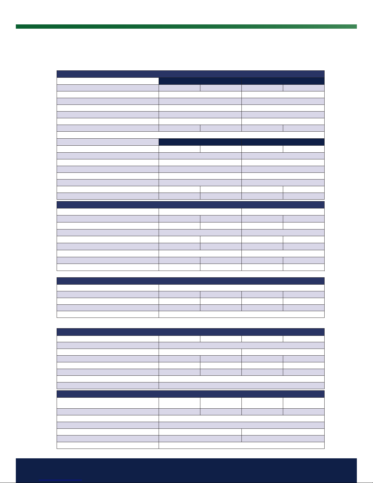
2. Technical data____________________________________________________ 10
2.1 Table 400 V 3N~ ___________________________________________ 10
2.2 Table 230 V 1N~____________________________________________ 12
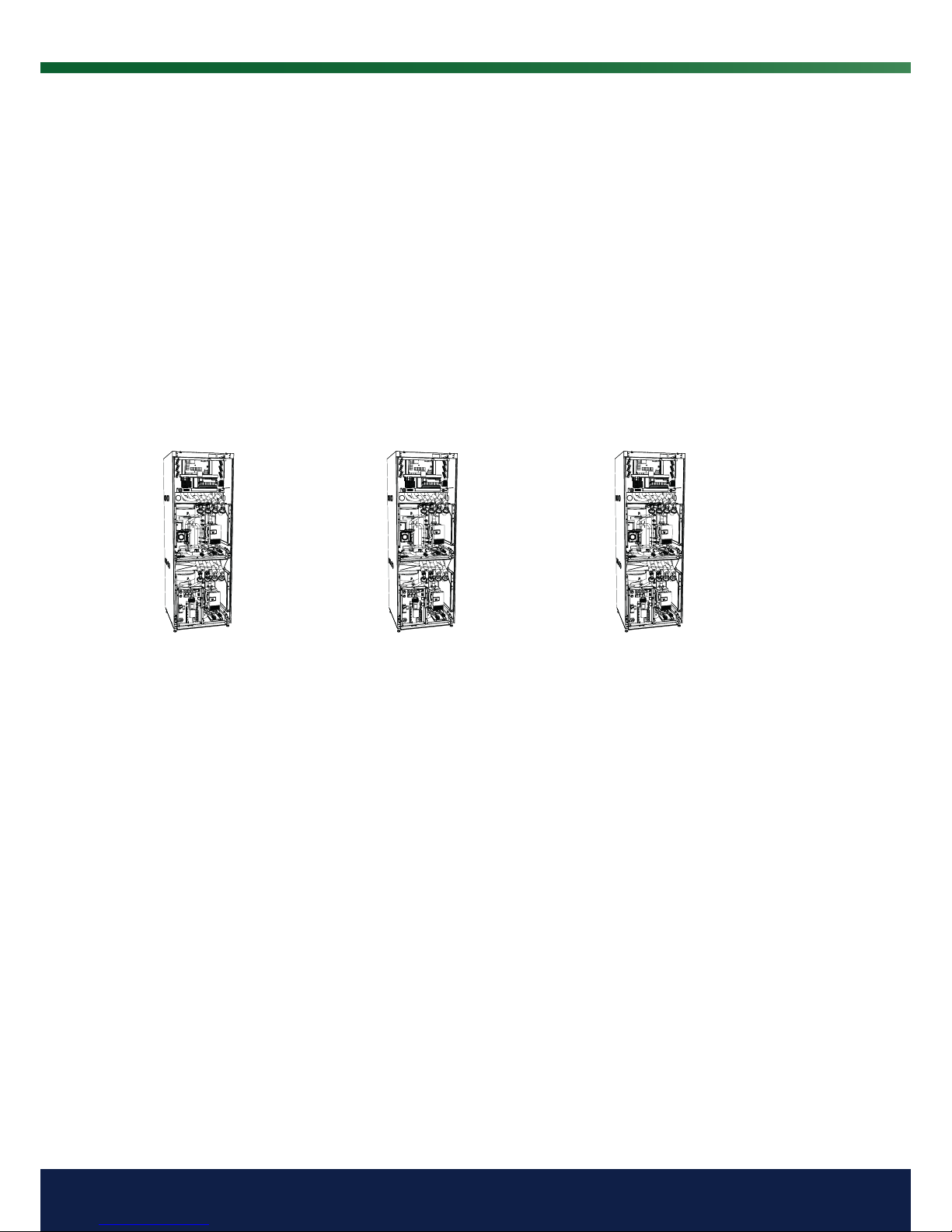
2.3 Component location_______________________________________ 13
2.4 Dimensional drawing ______________________________________ 14
2.5 Refrigerant system_________________________________________ 15
2.6 Operating range ____________________________________________ 15
3. Installation__________________________________________________________ 16
3.1 Delivery includes ___________________________________________ 16
3.2 Connection___________________________________________________ 17
3.3 Heat medium side__________________________________________ 18
3.4 Circulation pumps, heat medium side _______________ 19
3.4.1 Yonos Para pump curve ______________________________ 19
3.4.2 UPMGEO pump curve ________________________________ 19
3.5 Brine system_________________________________________________ 20
3.6 Brine pump___________________________________________________ 24
4. Electrical installation _________________________________________ 25
4.1 Alarm output_________________________________________________ 25
4.2 Groundwater heating______________________________________ 25
5. Connecting the control system_________________________ 26
5.1 CTC EcoPart i425-i435 Pro_____________________________ 26
5.2 CTC EcoPart 425-435____________________________________ 27
5.3 Series connection of heat pumps _____________________ 28
5.3.1 Terminated position ____________________________________ 28
5.3.2 Shielded communication _____________________________ 29
5.3.3 Example of series connection_______________________ 30
5.4 Power supply and communication 400V 3N~_____ 32
5.5 Power supply and communication 230V 1N~_____ 33
5.6 Wiring diagram CTC i425-i435 Pro 400 V 3N~ ___ 34
5.7 Cooling module 400V 3N~ ______________________________ 36
5.8 Wiring diagram CTC i425-i430 Pro 230 V 1N~ ___ 38
5.9 Cooling module 230V 1N~ ______________________________ 40
6. First start ___________________________________________________________ 41
7. Operation and Maintenance______________________________ 42
7.1 Periodic maintenance_____________________________________ 42
7.2 Shut-down ___________________________________________________ 42
7.3 Service position_____________________________________________ 42
8. Troubleshooting/appropriate measures ___________ 43
8.1 Air problems _________________________________________________ 43
8.2 Alarms _________________________________________________________ 43
8.3 Noise/vibrations_____________________________________________ 43
8.4 CTC Basic Display _________________________________________ 43
8.5 Safety risk ____________________________________________________ 43
8.6 Display “Lockout” __________________________________________ 43
Declaration of Conformity________________________________________ 44