CTC Union PS12A User manual

M N X 1 0 0 1 1 R E V C ●7 / 3 0 / 2 0 1 8 1
ConnectionTechnologyCenter,Inc.●7939RaeBoulevard●Victor,NY14564●(585)924-5900
`
Power Supply
12-Channel Rack Mountable Power Supply
PS12A

C O N T E N T S
M N X 1 0 0 1 1 R E V C ●7 / 3 0 / 2 0 1 8 2
ConnectionTechnologyCenter,Inc.●7939RaeBoulevard●Victor,NY14564●(585)924-5900
SECTION 1: OVERVIEW.................................................................................................................................. 4
Introduction ................................................................................................................................................ 4
Specifications ............................................................................................................................................ 5
Environmental....................................................................................................................................... 5
Electrical................................................................................................................................................ 5
Physical.................................................................................................................................................. 5
SECTION 2: INSTALLATION............................................................................................................................ 6
Description................................................................................................................................................ 6
SECTION 3: OPERATION ................................................................................................................................ 8
Operating Procedure................................................................................................................................. 8
SECTION 5: MAINTENANCE.........................................................................................................................14
Maintenance ...........................................................................................................................................14
General................................................................................................................................................14
Warranty .............................................................................................................................................14

F I G U R E S
M N X 1 0 0 1 1 R E V C ●7 / 3 0 / 2 0 1 8 3
ConnectionTechnologyCenter,Inc.●7939RaeBoulevard●Victor,NY14564●(585)924-5900
Figure 1 –PS12A Layout Diagram ................................................................................................................. 7
Figure 2 –PS12A Terminal Block Layout....................................................................................................... 7
Figure 3 –Constant Current Circuit ............................................................................................................10

S E C T I O N 1 : O V E R V I E W
M N X 1 0 0 1 1 R E V C ●7 / 3 0 / 2 0 1 8 4
ConnectionTechnologyCenter,Inc.●7939RaeBoulevard●Victor,NY14564●(585)924-5900
Introduction
PRO PS12A power unit is a 19 inch wide by 1 3/4 high rack mountable, line powered current
source power units designed to power 12 channels of regulated current style sensors and in-
line charge amplifiers.
NOTE: SENSORS may refer to accelerometers, pressure sensors, hammers and force
transducers, etc. The words SENSOR and TRANSDUCER are used interchangeably in this guide.
PRO model PS12A can support up to 12 channels, simultaneously. The sensor signal, riding atop
an approximate +12 volt bias level is decoupled from this DC bias by use of a 10µF coupling
capacitor for each channel.
The PS12A has a sturdy, powder-coated aluminum case that fits standard 19” racks. The front
panel has a convenient switchable output BNC to monitor a single channel at a time. The switch
also selects the channel of the easy to read 7 segment bias display. All channels have a red-
green LED sensor condition indicator light.
On the Back Panel, there are 12 sensor BNC’s, as well as 12 output BNC’s. In addition there are
terminal block inputs that can be used for both the sensors and outputs, in lieu of BNC jacks.

S E C T I O N 1 : O V E R V I E W
M N X 1 0 0 1 1 R E V C ●7 / 3 0 / 2 0 1 8 5
ConnectionTechnologyCenter,Inc.●7939RaeBoulevard●Victor,NY14564●(585)924-5900
Specifications
RACK MOUNTED POWER SUPPLY
Table 1. Specifications
SPECIFICATION
VALUE
UNITS
SENSOR SUPPLY CURRENT (Factory set at 5 mA)
2.0 –10.0
mA
NUMBER OF SENSOR CHANNELS
12
SENSOR EXCITATION VOLTAGE (COMPLIANCE VOLTAGE)
+24
VDC
VOLTAGE GAIN
UNITY
FRONT PANEL LED VOLTMETER F.S.
+24 VDC
OUTPUT COUPLING CAPACITOR
10
µF
COUPLING TIME CONSTANT
w/ 10 MΩ LOAD
w/ 1 MΩ LOAD
100
10
SEC
SEC
LOWER -3db FREQUENCY
w/ 10 MΩ LOAD
w/ 1 MΩ LOAD
.0016
.016
Hz
Hz
HIGH FREQUENCY RESPONSE
DETERMINED BY SENSOR,
CABLE LENGTH AND SIGNAL LEVEL LENGTH AND SIGNAL LEVEL
ELECTRICAL NOISE, WIDEBAND
150
µV, RMS
SENSOR CONNECTORS, REAR PANEL
BNC, TERMINAL
BLOCK
JACK
OUTPUT CONNECTORS REAR PANEL
BNC, TERMINAL
BLOCK
JACK
OUTPUT CONNECTOR FRONT PANEL
BNC
JACK
POWER INPUT
FUSED IEC
CONNECTOR
SOCKET
POWER REQUIRED
13.0
VA
LINE VOLTAGE REQUIRED
110-220
VAC
SIZE (H x W x D)
1.7 x 19x 6.5
44 x 483 x 171
INCHES
MILLIMETERS
WEIGHT
3.7
1.7
POUNDS
KILOGRAMS

S E C T I O N 2 : I N S T A L L A T I O N
M N X 1 0 0 1 1 R E V C ●7 / 3 0 / 2 0 1 8 6
ConnectionTechnologyCenter,Inc.●7939RaeBoulevard●Victor,NY14564●(585)924-5900
Description
These power units contain a regulated DC power supply and constant current circuits which
supply constant current DC power to 12 sensor channels. The constant current sources can be
individually adjusted to provide from 2 to 20 mA of drive current per channel.
There is also provision for operation from external +24 VDC batteries or DC power packs for use
where AC power is not available.
The front panel has 12 red/green LED’s so that sensor condition can be determined at a glance.
On the rear panel there are 12 Sensor BNC jacks and 12 Output BNC jacks. In addition, there are
terminal block inputs that can be used in lieu of BNC’s.
A rotary selector switch (12 position) on the front panel allows the monitoring of the DC bias
voltage of each sensor. This is a very handy troubleshooting tool for system checks. Readout is
by a front panel mounted 3 digit seven segment display. Also connected to this rotary switch is
a front panel mounted BNC ‘Monitor’ jack which allows the user to look at the signal from the
sensor connected to the selected channel. In this way each channel’s signal may be inspected.
A three position power switch on the front panel selects AC power or Ext DC power with an ‘off’
position included. The rear panel has a set of twin banana jacks for connection to the external
DC power source. The rear panel also contains the fuse holder and the IEC power entry
connector.

S E C T I O N 2 : I N S T A L L A T I O N
M N X 1 0 0 1 1 R E V C ●7 / 3 0 / 2 0 1 8 7
ConnectionTechnologyCenter,Inc.●7939RaeBoulevard●Victor,NY14564●(585)924-5900
Figure 1. PS12A Power Supply Layout Diagram
Figure 2. PS12A Terminal Blocks expanded

S E C T I O N 3 : O P E R A T I O N
M N X 1 0 0 1 1 R E V C ●7 / 3 0 / 2 0 1 8 8
ConnectionTechnologyCenter,Inc.●7939RaeBoulevard●Victor,NY14564●(585)924-5900
Operating Procedure
OPERATION FROM AC POWER MAINS
Plug the line cord into the appropriate AC power source and move the power switch toggle to
the ‘AC POWER’ position. The indicator lights on the front panel will glow and the voltmeter will
indicate full scale with no sensors attached to the sensor jacks.
If these indications are not present, check the fuse at the rear panel. If it is blown, replace it
with a 1/4 Amp 3AG fuse only.
OPERATING THE POWER UNIT
Connect the sensor to any one of the ‘Sensor’ jacks at the rear panel of the power unit. Rotate
the channel selector switch on the front panel to the number of the channel into which the
sensor has been connected. The front panel 10-segment LED voltmeter should indicate near
mid-scale if the sensor and cable are intact and working normally.
In like manner, connect up to the maximum number of sensors and check the bias indications
of each for normal operation. If the monitor voltmeter reads full scale, this means:
1. That there is no sensor connected to that channel.
2. The cable to the sensor is open.
3. The sensor is not functioning correctly.
After ensuring that all channels are functioning normally, connect the ‘Output’ connectors to
the readout instrument using the rear sets of output jacks. You are now ready to proceed with
the measurement task.
Remember, the rear panel BNC monitor jack allows the user to monitor the signal from any
channel selected by the front panel rotary selector switch. Thus, each channel may be
monitored for normal operation, even while that channel is being monitored at the rear output
jack for that channel.

S E C T I O N 3 : O P E R A T I O N
M N X 1 0 0 1 1 R E V C ●7 / 3 0 / 2 0 1 8 9
ConnectionTechnologyCenter,Inc.●7939RaeBoulevard●Victor,NY14564●(585)924-5900
COUPLING TIME CONSTANT
A feature of this system is that power to operate the internal IC in the sensor and the signal
from the sensor both flow over the same pair of wires. The DC bias from the sensor amplifier is
blocked by a 10 µF capacitor in the power unit while the AC or dynamic signal is allowed to pass
through this blocking capacitor to the output jack.
The value of the coupling capacitor and the resistive load of the readout instrument (in parallel
with the pulldown resistor) determine the discharge time constant of the power unit/readout
combination and set the low frequency performance of this system.
NOTE: The discharge time constant of the sensor itself must be considered also but for this guide, we
will concentrate on the effect of the power unit/readout combination only. The operating guide
supplied with the sensor will address the low frequency response of the sensor.
In the PS12 the value of the coupling capacitor is 10µF and the pulldown resistor is 1 MΩ. This
yields a coupling time constant of:
SETTING THE CONSTANT CURRENT SENSOR DRIVE CURRENT LEVEL
For most users, this section may be skipped over for now.
The sensor drive current levels are factory set at 5 mA per channel. This is a high enough level
for most normal applications and should only be changed when driving very long cables with
sensors measuring very high frequencies. For best thermal stability and lowest noise, it is
recommended that the sensors operate from 2 to 5 mA of drive current.
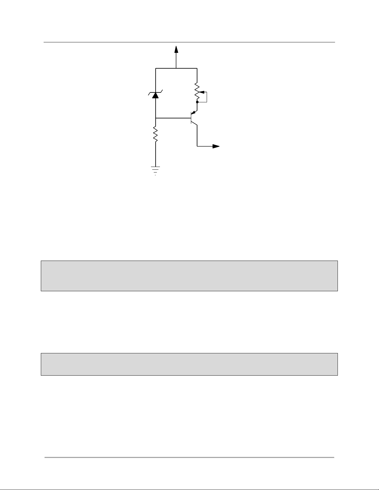
These power units use a clamped base transistor circuit as the constant current source. (Figure
3).
The constant current out of the collector is set by the current flowing through the emitter
resistor. The base is clamped by the zener/resistor combination to a fixed voltage, and this in
turn sets the emitter voltage via the fixed base to emitter voltage characteristic of the
transistor. Thus by varying the potentiometer in the emitter circuit, we may set the constant
current to any desired level.
Eq 1. TC = RC = 1 x 106 x 10 x 10-6 = 10 Seconds

S E C T I O N 3 : O P E R A T I O N
M N X 1 0 0 1 1 R E V C ●7 / 3 0 / 2 0 1 8 10
ConnectionTechnologyCenter,Inc.●7939RaeBoulevard●Victor,NY14564●(585)924-5900
However, if it is found that the measurement situation calls for higher drive currents, it may be
necessary to increase this level. To change the level of sensor drive current, proceed as follows:
1. Remove the top cover by removing the top and bottom screws, as well as the two top
mounting screws for the front and back panels.
CAUTION: FOR THE FOLLOWING ADJUSTMENT, USE A NON-METALLIC SCREWDRIVER SINCE VOLTAGES
ARE PRESENT IN THIS UNIT WHICH CAN CAUSE ELECTRIC SHOCKS WHICH COULD RESULT IN FATAL
INJURY.
2. Set the mA range of a DC milli-ammeter to 20 mA and connect the + lead to the center
conductor of a sensor channel and connect the other lead to ground return (the outside
shell of the same connector). Read the constant current, then adjust the sensor drive
current adjust pot to obtain the desired drive current for that channel. Each channel
may be individually adjusted in this manner.
NOTE: Although it may be possible to do so, do not set the drive current above 20 mA. This could be
harmful to the sensor.
SENSOR DRIVE VOLTAGE (COMPLIANCE VOLTAGE) SETTING
It should not be necessary under normal conditions to ever need to adjust this setting. The
output voltage of the DC power supply is regulated by a very stable 3-terminal voltage
CONSTANT
CURRENT
OUTPUT
ZENER
DIODE
R
Z
TRANSISTOR
CURRENT
ADJUST POT
+26 VDC
Figure 3. Constant Current Circuit

S E C T I O N 3 : O P E R A T I O N
M N X 1 0 0 1 1 R E V C ●7 / 3 0 / 2 0 1 8 11
ConnectionTechnologyCenter,Inc.●7939RaeBoulevard●Victor,NY14564●(585)924-5900
regulator. This voltage is factory set to provide +24 VDC compliance voltage at +5 mA output
level.
EXTERNAL POWER SOURCES
Model PS12A may be powered by an external DC power source such as batteries or a DC power
supply. 24 VDC is recommended but voltages down to 18 volts are sufficient. (With voltages as
low as +18 volts, the front panel LED voltmeter may not function normally, however the unit
will work normally otherwise.)
To use an external supply, connect the leads from the power source to the twin banana plugs at
the rear panel. Be sure to observe the proper polarity as marked at the rear panel. A protective
diode is built into the PS12A to preclude damage from reverse polarity connection of the power
source.
Switch the front panel toggle switch to ‘EXT PWR’. With +24 VDC as the power source, It will be
noticed that the LED voltmeter may indicate one segment lower than normal when there is no
sensor connected to that channel. This is normal and will not affect the operation of the units
or the sensors.
When operating from batteries or an external DC power supply, the operation of the sensors
and power units, aside from the minor points mentioned, will be the same as with AC power.
The center position of the power toggle switch is the “off” position and should be used when
the instrument is not taking data, to prolong battery life.

S E C T I O N 5 : M A I N T E N A N C E
M N X 1 0 0 1 1 R E V C ●7 / 3 0 / 2 0 1 8 12
ConnectionTechnologyCenter,Inc.●7939RaeBoulevard●Victor,NY14564●(585)924-5900
Maintenance
Once the product has been installed, minimal maintenance will be required. Basic visual checks
to ensure integrity should be made periodically.
General
Under normal usage, no routine maintenance is necessary for these instruments. Should it be
necessary to replace the fuse, unplug the unit from the AC line power source, remove the cap
from the fuse holder and remove the fuse, Replace only with a 250V/ 0.6A fuse.
Should a problem arise with the power unit, contact the factory for help in analyzing the
problem and/or for instructions on sending the unit back for evaluation.
Should the PS12 develop a problem, contact the factory Service Department for help in trouble
shooting or for instructions in returning the unit to the factory for evaluation. At this time, a
Returned Material Authorization (RMA) number will be assigned to help track the unit through
the repair process, should it be necessary to return the unit to the factory.
Warranty
If any PRO product should ever fail, we will repair or replace it at no charge, as long as the
product was not subjected to misuse, natural disasters, improper installation or modification
which caused the defect.
Table of contents
Popular Power Supply manuals by other brands

Thermal Arc
Thermal Arc PowerMaster 250 operating manual

Maxtec
Maxtec B&K Precision 1660 instruction manual

ITW
ITW SIMCO ION D Series Installation and operating instructions

Gallagher
Gallagher M1100 instructions

Hama
Hama Universal Notebook Power Supply Operating instruction

Pulsar
Pulsar PSP54006 quick start guide