CTD DM200R User manual

INSTRUCTION BULLETIN
& MAINTENANCE MANUAL
FOR CTD MODELS
DM200R & DM400
05.16
CTD MODEL NO:
CTD SERIAL NO:
MANUFACTURE DATE:
DISTRIBUTOR PURCHASED THROUGH:
(IF ANY)
CTD MACHINES
2382 East 48th Street
Vernon, CA 90058
Tele (213) 689-4455 • FAX (213) 689-1255
World Wide Web: http://www.ctdsaw.com
e-mail: ctdsaw@ctdsaw.com

Subject Page No.
Machine Requirements............................................................................................................ 2,3
Installation and Set-Up............................................................................................................ 4,5
Electrical Installation................................................................................................................ 6
Safety Instructions................................................................................................................... 7
How to Operate the Machine................................................................................................... 8-12
Air Pneumatics........................................................................................................................ 13-16
Repair and Service.................................................................................................................. 17
200 Series Blade Guard Exploded View................................................................................... 18
200 Series Right Saw Exploded View....................................................................................... 19
DM200 Base Exploded View................................................................................................... 20, 21
DM200 Stand Exploded View................................................................................................. 22
400 Series Spindle Exploded View........................................................................................... 23
400 Series Blade Guard Exploded View................................................................................... 24, 25
400 Series Base & Arm Exploded View................................................................................... 26-29
DM400 Stand Exploded View................................................................................................. 30
DM200 Spindle Installation Prosedure..................................................................................... 31
Spindle Diagrams..................................................................................................................... 32
DM400 Spindle Installation Prosedure..................................................................................... 33
Pivot Shaft Diagrams................................................................................................................ 34
Warranty & Guarantee............................................................................................................. 34
Machine Requirements:
MODEL NO:_____________ SERIAL NO:________________
Cutting Capacities
Model DM200R
90 Cutting:
2” (51mm) high x 7-3/4” (197mm) wide
3-3/4” (95mm) high x 3-3/4” (95mm) wide
45 Cutting:
1-1/2” (38mm) high x 4-7/8” (123mm) wide
2” (57mm) high x 4-1/4” (108mm) wide
3-1/2” (89mm) high x 3-1/2” (89mm) wide
DM400, 16” Blade Capacity
90 Cutting:
5” (127mm) high x 6” (152mm) wide
3” (76mm) high x 11” (280mm) wide
45 Cutting:
3” (76mm) high x 8” (203mm) wide
5” (127mm) high x 5” (127mm) wide
-2-
DM400, 20” Blade Capacity
90 Cutting:
5-1/2” (140mm) high x 11” (280mm) wide
6” (152mm) high x 10” (254mm) wide
45 Cutting:
5-1/2” (140mm) high x 8” (203mm) wide
6” (152mm) high x 6” (152mm) wide

Pneumatic Requirements: 2 CFM per 10 strokes at 75 PSI (.086 cubic meters at 5.4 kg/cm2).
Dust Collection Requirements: 800 CFM at each 2” outlet for DM200R; 1000 CFM at each 4” outlet for DM400.
Model No. Motor Size Required Amperage Breaker Needed**
DM200R 2 H.P. 1 Phase, 230 Volt 12.5 amps each motor 40 amp
DM200R 2 H.P. 3 Phase, 230 Volt 5.4 amps each motor 20 amp
DM200R 2 H.P. 3 Phase, 460 Volt 2.7 amps each motor 15 amp
DM200R 3 H.P. 3 Phase, 230 Volt 7.4 amps each motor 30 amp
DM200R 3 H.P. 3 Phase, 460 Volt 3.7 amps each motor 20 amp
DM400 8 H.P. 3 Phase, 230 Volt 20 amps each motor 60 amp
DM400 8 H.P. 3 Phase, 460 Volt 10 amps each motor 40 amp
DM400 10 H.P. 3 Phase, 230 Volt 26 amps each motor 60 amp
DM400 10 H.P. 3 Phase, 460 Volt 13 amps each motor 40 amp
DM400 15 H.P. 3 Phase, 230 Volt 34 amps each motor 60 amp
DM400 15 H.P. 3 Phase, 460 Volt 17 amps each motor 60 amp
**Breaker needed if both motors on the same circuit breaker
Cutting Tool Requirements: Heavy, rigid plate blades. 12” blades: .100 to .110 plate
16” blades: .120 to .130 plate
20” blades: .150 to .160 plate
Space Requirements
For Models DM200R & DM400 Only
DM200R 30” (76cm)
DM400 45” (114cm)
120” (305cm)
132” (335cm) - DM400 ONLY
Note: The floor stand must be shimmed, leveled and bolted to the floor to eliminate vibration. Use holes provided in
support legs for this purpose.
DM200R 35” (89cm)
DM400 37” (94cm)
-3-
DM200R 60” (152cm)
DM400 77” (196cm)

Installation and Set Up:
The CTD saw you have purchased is designed to cut wood, aluminum, plastic and steel, with of course the proper
blades and conditions. For the material you are cutting, please refer to the cutting instructions for each type. The machine
must be leveled and framed in or bolted to the floor. See “Alignment of Saw “on page 5.
The Model DM200R uses NEMA 56 Frame 2 H.P., 3450 RPM, 60 Hertz TEFC Motors.
The DM400 uses NEMA 213T or 215T Frame 8 H.P. or 10 H.P., 1725 RPM, or 15 H.P., 3450 RPM, 60 Hertz TEFC
Motors. CTD uses a speed up drive so that the blade will run at approximately 12,500 SFPM on a 16” blade and 14,000
SFPM on a 20” blade.
IMPORTANT: Before operating the saw, please be sure to read the “SAFETY INSTRUCTIONS TO THE
OPERATOR” (see Page No. 7).
Blade Installation: (for model DM200R)
Before setting blades on spindle, always shut off or disconnect air supply. The model DM200R uses a lower rotating
blade guard. With Motor OFF and Power Disconnected, rotate Lower Blade Guard (p/n 200A270) up into main
blade guard. Slide link puller (p/n 200M360Lor R) off screw and bushing through large hole in slot. Loosen and remove
four machine nuts on Blade Guard Cover (p/n 200F250Lor R) and remove entire Blade Guard Cover Assembly (p/n
200E250Lor R). The entire Blade Guard Cover Assembly, consisting of Bearing Housing, Lower Blade Guard and Link
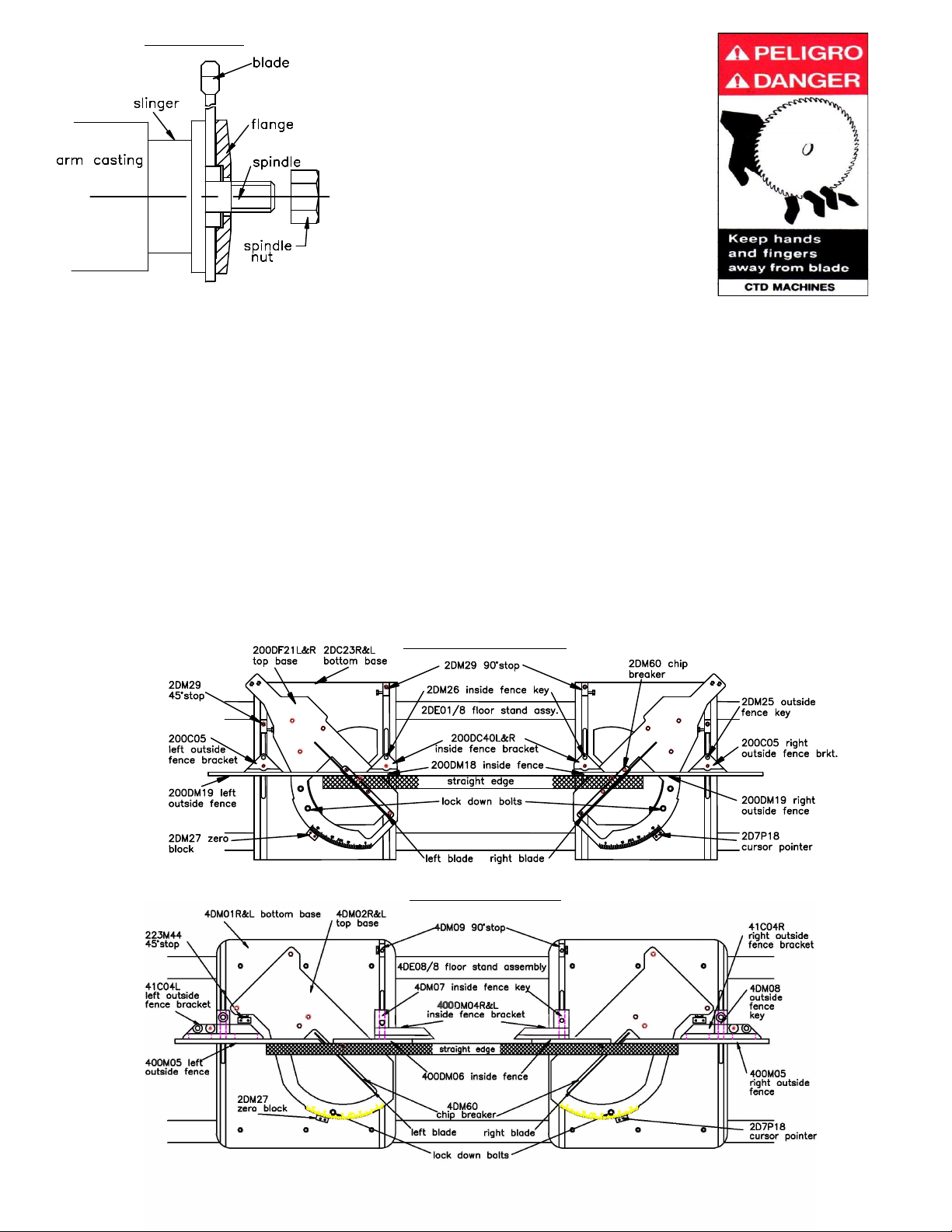
Puller with Pawl (p/n 200M261) will come off as one piece, exposing spindle nut and flange. (Refer to Page No. 18.)
After blade has been placed on spindle and tightened (see Blade Installation below), replace Blade Guard Cover Assem-
bly with Housing and Link Puller by reversing the sequence.
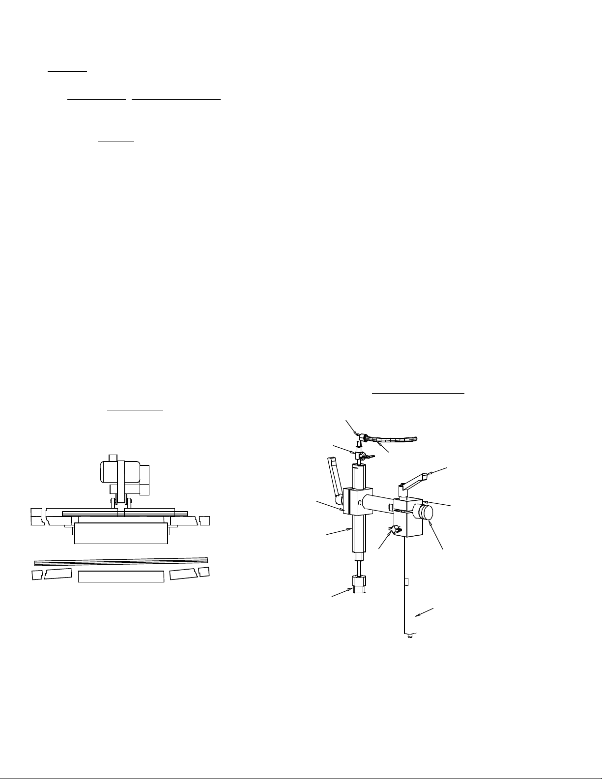
For DM400 loosen wing nut on bottom blade guard strap and swing down.
Now lift main blade guard, exposing spindle assembly.
To install or remove blade:
1. Hold blade in hand with a rag covering sharp tips, or lower blade into a piece of wood so it will not
rotate. Push down with wrench on spindle nut. Remove spindle nut and outer flange.
2. Place blade on spindle with tips pointing down. Make sure slinger (inner flange) and blade surface are
CLEAN before putting blade on spindle. This is a critical surface and is ground within .0005 flatness.
Any debris or dust will wear this surface. Wipe both surfaces (blade and slinger) with a clean rag.
A. The blade must ALWAYS rotate to the rear of the machine on the underside of the blade
Always check rotation before cutting a piece of material.
3. Replace outer flange and nut as before and tighten (refer to Diagram “A” on Page 5). Pull up with your wrench.
Do not over tighten. Snugging the blade is all that is necessary. Replace Blade Guard parts as before or close
door to cover the blade.
If blades were purchased from CTD, your machine has been set with your blades. If a chip breaker is included on your
machine, it has been cut with the blades purchased from CTD. If not, blade diameters and widths vary and your chip breaker
has not been cut. Cut chip breaker using your blades VERY SLOWLY the first cut through.
Note: Also make sure blades do not contact top base in the down position. Adjust downstop if necessary.
-4-
Blade Guard:
DM200R: The blade and belt drive are enclosed. When the saw arms are lowered, the lower blade guard rotates up into the
main blade guard. The blade continues through the work as the lower blade guard rotates up, via linkage arm. Cut only
material that fits into the cutting capacity of the machine. Damage to the blade guard will result if too large
material is attempted to be cut.
DM400: When the saw arms are lowered, the Blade Guard Bearing, P/N 2B2P05 contacts Blade Guard Guide, P/N
4BM68. The blade continues through the work as the blade guard rides forward on the guide. Always keep the blade
guard guide as close as possible to the material for maximum protection to the operator.

Diagram “B” DM200R
Diagram “B” DM400
-5-
Diagram “A”
These machines are general purpose in
their design, therefore the user should
attach any additional guarding to the
blade guard or table base if the cutting
application causes unsafe blade exposure.
This label is attached to the blade guard.
Never put hand or fingers near or
under the moving blade.Use a piece
of wood to remove short pieces from saw
Alignment of the Saw:
1. The Floor Stand Assembly and base of double mitre saws must be leveled lengthwise, and front to
back. The front and rear tubes must be parallel, in good alignment, and not twisted. Bolt down holes
are provided in the support legs of the floor stand for this purpose.
2. In the operation of the double end mitre saws, it is very important that long work be supported in the
center to avoid springing or vibration of the work as it is being cut. If the work is allowed to “sag”,
inaccurate cuts will be made. This problem is eliminated by the use of the Center Work Support
accessory (item CWS), which may be purchased along with the machine.
3. The fences on both heads must be in good alignment with each other. This is easily accomplished as
the fences are keyed, and will maintain their relationship to the centerline of the machine. A straight
edge should be used for setting the fences (see Diagram “B“ for each model machine).
4. The outside fences must be set close to the blades so that the scrap piece that drops does not bind
between the blade and fences. ALWAYS use outside fence as this acts as a back support for the scrap
piece. If you remove the fence, the scrap piece will be unsupported and can be thrown into the blade
causing damage to it and possibly to the operator.

Electrical:
The DM200R uses two NEMA 56 Frame, 2 H.P. 3 Phase, 3450 RPM, 60 Hertz TEFC Motors.
The DM400 uses two NEMA 213T or 215T Frame, 8 H.P. 3 Phase, 1725 RPM, 60 Hertz TEFC Motors.
CTD uses a speed up so that the blades run at approximately 12,000 SFPM. Electrical installation should
be performed by a qualified and certified electrician. It is highly recommended that a lock-out or disconnect
switch be located close to the machine between your main electrical panel and the machine. This disconnect
switch is used to shut off power to the machine and should be used whenever the blades are changed, or at anytime
the machine is serviced and the blades are exposed.
A Magnetic Starter for each motor is supplied. This starter protects the motor from overheating and will not allow
the motor to restart itself after power outages or undervoltage situations.
Electrical Installation of Power to Starter by a Qualified Electrician:
All wiring from the motors to the starter has been completed and tested at the factory several times.The voltage
has been clearly tagged. DO NOT CONNECT ANY VOLTAGE THAT IS DIFFERENT THAN
THE TAGGED VOLTAGE, AS THIS MAY CAUSE SEVERE DAMAGE AND DANGER. Consult the factory if any
changes are needed.
Bring power lines to the top of each Magnetic Starter. Use dust-proof connectors if available.
Single Phase Motor Replacement:
Connect leads to L1 (line 1) and L2 for single phase motors. (See Wiring Diagram for Single Phase Motors
on Page No. 7.) Green ground wire must be grounded to enclosure. If using type “SO” wire and plug, use
a romex connector through starter box and a grounded plug. Be sure to check rotation. The blade must
rotate down and to the rear on the underside of the blade.
Three Phase Motor Replacement:
Connect incoming power line leads to L1 (line 1), L2 and L3. (See Wiring Diagram for Three Phase Motors
on Page No. 7.) Green ground wire must be grounded to enclosure. Be sure to check rotation as polarities may be
different. The blade must rotate down and to the rear on the underside of the blade. If a change in rotation is necessary,
reverse any two of the incoming power wires. Example: If the blades are running backwards and incoming wires are
connected White L1, Black L2, Red L3, switch the
Black wire with the Red so that Black is connected to L3 and Red is connected to L2. This will change the motor
to rotate properly.
-6-
MOTOR LOAD AMPERES
Motor Model Frame 208 Volt 230 Volt 460 Volt
2 H.P. 3 Phase DM200R 56Z 5.7 amps 5.4 amps 2.7 amps
2 H.P. 1 Phase DM200R (optional) 56Z N/A 12.5 amps N/A
3 H.P. 3 Phase DM200R (optional) 56Z 7.8 amps 7.4 amps 3.7 amps
8 H.P. 3 Phase DM400 213T 21.5 amps 20 amps 10 amps
10 H.P. 3 Phase DM400 (optional) 215T 28 amps 26 amps 13 amps

Safety Instructions to the Operator:
1. KNOW YOUR CTD SAW.Read this instruction manual carefully. Learn the operation, application, and
limitations, as well as the specific potential hazards peculiar to this machine.
2. Avoid accidental starting. Make sure switch is OFF before plugging in power cord. A Magnetic Starter is
provided to give the operator added protection. (OSHA required by user.)
3. Always use a plug equipped with a ground.
4. Always keep blade guard in place. Do not wire-up or chain-up, so that blade is exposed.
5. Be sure all unnecessary tools are removed from machine before turning on power.
6. Use safety goggles. Also use a face or dust mask if operation is dusty.
7. Support work. To maintain control of work at all times, it is necessary that material be level with cutting
surface.
8. Wear proper apparel. Do not wear loose clothing or jewelry. Do not wear a tie or gloves. These items can
get caught in the moving parts of the machine.
9. Do not over-reach. Keep your proper footing and balance at all times.
10. Maintain your machine in top condition. Use proper blades. Clean machine weekly for proper maintenance.
11. Keep work area clean. Cluttered areas, benches and slippery floors invite accidents.
12. Avoid dangerous environments. Keep work area well illuminated.
13. Wear ear protection if exposed to long periods of very noisy shop operations.
14. Keep visitors away. All visitors should be kept a safe distance from work area.
15. Do not force the machine. The saw will do a better job and be safer to operate at the speed for which it was
designed. Forcing the saw can be very hazardous to the operator.
16. Use recommended accessories. Use of other accessories may be hazardous. Use this instruction manual or
consult CTD for the proper accessories available.
17. Do not drown the blade using a steady stream of coolant when cutting non-ferrous materials. Only spray the
work to cool it.
18. Be sure to use the proper blade for the particular material to be cut.
19. Disconnect power cord before adjusting, servicing, and before changing belts, or for installing accessories.
20. Safety is a combination of operator COMMON SENSE and ALERTNESS at all times when the machine is
being used.
21. WARNING!!! DO NOT ALLOW FAMILIARITY (GAINED FROM FREQUENT USE OF YOUR SAW) TO
DULL YOUR AWARENESS!! ALWAYS REMEMBER THAT A CARELESS FRACTION OF A SECOND IS
SUFFICIENT TO INFLICT SEVERE INJURY!!
-7-
Wiring Diagram for Magnetic Starter

-8-
How to Operate a Double End Trim Saw:
Before operating the machine, please read the “Safety Instructions to the Operator” on Page No. 8. Other important
information and features need to be learned before operating the machine.
Rotation:
The blade must rotate to the rear of the machine on the underside of the blade.
Blade Guard:
Model DM200R : The blade and belt drive are enclosed. When the saw arms are lowered, the lower blade guard rotates
up into the main blade guard. The blade continues through the work as the lower blade guard rotates up via the linkage arm.
Model DM400: When the saw arms are lowered, the Blade Guard Bearing, P/N 2B2P05 contacts Blade Guard Guide, P/
N 4BM68. The blade continues through the work as the blade guard rides forward on the guide. ALWAYS keep Blade
Guard Guide as close to the material as possible for maximum protection of the operator.
These machines are general purpose in their design. Therefore, the USER should attach any additional guarding to
the blade guard or table base if the cutting application causes unsafe blade exposure.
Positioning the Work and Alignment of Fences:
Fences should be set so that the centerline of the work is either to the front, or on the centerline of the blade. Fences must be
adjusted so that short pieces cannot be trapped between the blade and the fences. Fences must be in line with each other—
front to back (see Diagram “B“). If fences are set 5/8’ in front of the centerline, then when changing mitre angle, the length
dimension at 45 and 90 degrees will stay the same. No adjustment to measuring scale will be necessary. However, any other
angles require slight adjustment of the scale. Note: The scrap drop off piece needs to be backed up by the rear outside
fence. If the trimmed cut-off material is not supported by the rear outside fence, the cut-off piece can catch on the blade with
the possibility of firing the scrap piece into the blade. This will cause damage to the blade, the blade guard, and has the
potential for harming the operator. Always back up the cut-off trim piece with the outside fence supplied.
Measuring Scale and Pointer for Length:
The length measuring scale (used to determine length of cut between two saw heads) is located on top of precision
gear rack. The measurement rule and bar must be reset if the fences are moved or the blades are changed. If a small
adjustment is needed, this can be accomplished by adjusting the pointer located on the right saw head carriage or
base. The measurement rule and bar can be reset by loosening screws that hold it in place on top of gear rack. Move
the bar with tape, left or right as necessary, to correct length dimension between the two blades.
To Move Saw Head Base:
1. Loosen hand knob located in front of saw head base.
2. Rotate crank handle until pointer registers desired dimension. Always move saw head base in one
direction to eliminate any backlash between gear rack and pinion.
3. Tighten hand knob. This automatically squares up saw head base to the front rail or tube.

Digital Length Measurement System:
The length of cut is determined the same way as explained on Page No. 9. The length measurement is now displayed
in thousanths of an inch, (i.e. 1/16”, 1/32”, or metric dimensions) by pressing the mode button on the digital display.
Since the right saw head base is usually the movable saw head, the digital scale will read to the negative number.
When setting the length between the two saw heads;
1. Manually use a scale or cut a piece of wood to determine the exact length between blades.
2. Hold the negative button down until the correct length dimension appears. (Negative only if right saw
head base is movable.)
3. The scale is now accurately set for length dimension for the angle and fence position chosen. If fences
are moved front to back, or if angle changes (unless fences set on the centerline), then the display will
need to be reset.
Mitre Angle Adjustment:
To change angle on all machines, locate lock down bolts in Diagram “B” on Page No. 5 for particular machine pur-
chased—Models DM200R and DM400.
1. Loosen lock down bolts on each saw head with an Allen wrench (5/16” for Model DM200R or
3/8” for DM400).
2. Manually rotate Top Base to desired degree setting, aligning angle mark and pointer. 45 & 90 stops
are provided.
3. Tighten lock down bolts.
Saws are designed to mitre toward each other as shown in Diagram “B“. If you have purchased a machine with angular
adjustment in the opposite direction, it is necessary to remove lock down bolts and reposition in additional tapped holes
provided. Also, the inside fences may have to be removed or repostioned and a Center Work Support (item CWS)
added. Please consult factory for this special modification.
-9-
Cutting:
A double end trim saw operates by making two cuts at the same time on both ends of a piece of material. The material is
positioned against the rear inside fences, making sure any scrap (off each end, outside the two blades) is located against
outside fences. If scrap piece is not backed by the outside fence, it is possible this part will catch on the blade, causing
damage to the blade. The material to be cut must lay flat on the table base, or the blades may bind in the material. This can
damage the blade or throw the cut piece out of the saw, possibly harming the operator. The material is held in place with two
Vertical Inside Air Clamps which are actuated by a Foot Valve. The saw heads are then activated downward by a Two-Hand
Anti-Tie Down, Maintained Contact Control. See “AIR SYSTEM” on Page No. 13 for additional details.

1/4” elbow
B3P61
shut off
valve
200M22
vert. cyl.
brkt.
2B3P20
3” stroke
air cyl.
2B3P20C
vert. clamp
pad
200BIP22
wing nut
VC
1/4” red polyflo
200B7P19
adjustable
lock
200M21
vert. clamp
adjustment
brkt.
200M20B
horiz. bar adj.
for vert.
200M20
vert. clamp
support bar
Diagram “E”
Vertical Clamp Assy.
material must lay
flat on base and
work supports
never allow material to rest uneven
on base or work supports
-10-
Cutting Speed:
The blade is rotating at approximately 3700 RPM for Model DM200R. For Model DM400, the 16” machine’s blade rotates
at 2900 RPM and the 20” machine’s blade rotates at 2700 RPM. When moving the blade through the material, the blade
must NEVER be allowed to dwell in the work. If fine finishes are required;
1. Use a sharp blade.
2. Use a CONSTANT, EVEN PRESSURE when cutting through the material.
Clamping and Work Slippage:
The work must NEVER be allowed to move or vibrate as it is being cut, or inconsistent cuts will result. Two inside
Vertical Clamps, which hold material down against the table base are provided as a standard feature on all double end
trim saws. For odd shapes and profiles, additional clamping or fixturing may be necessary. Horizontal Clamps that
push the material back against fence, can be provided as an optional accessory. The Horizontal Clamps mount to the
Center Supports that hold the Vertical Clamps for the DM400. They mount to special inside supports for the DM200R. The
Horizontal Clamps are adjustable front to back on the Center Supports for different widths of material. The clamps are
actuated prior to the saw head by depressing the Foot Valve. An Anti-Tie Down, Two-Hand Control drives down the saw
heads. Check your material for squareness using a 90 square. Material that is out of square will move when it is cut, causing
irregular mitres. (See “IRREGULAR MITRES” on Page No. 17.) Additional tooling may be neeeded. Consult factory for
more information.
Cutting the Material:
The material to be cut (both the incoming pieces and the cut pieces) must lay flat on the table base, or the blade
may bind the material. THIS CAN DAMAGE THE BLADE OR THROW THE CUT PIECE OUT OF THE
SAW, POSSIBLY HARMING THE OPERATOR (see Diagram “C“ below).

Double Cutting Material for Two Pieces in One Pass on Symmetrical material only:
If your material is symmetrical on both sides and edges when looking at the end, then double cutting as shown
below would be an option. By placing a stop outside the left blade, two pieces can be cut simultaneously, one
between the two saws and one between the left saw head and stop. Double cutting is not possible on material that
is moulded or profiled on the top of the moulding.
Diagram “D”
Removing Material From the Blade:
If the machine is stalled while cutting, immediately shut saw off and disconnect power. NEVER attempt to free the
blade while the motor is still running. If a piece is bound on the blade, do not attempt to raise the blade out of the
material. Instead, tap the piece down on both sides of the blade with light pressure until the piece has freed the blade.
Cutting Wood:
While wood is generally soft and simpler to cut than aluminum, it requires that the material be held in place as the
blades pass through the material. CTD suggests using a Carbide Blade with an Alternate Top Bevel (AT) for lighter
wood sections and picture frame mouldings. This type of blade gives the finest of finishes. No ONE blade will cut
all material perfectly. High lacquers or mica mouldings require a special modified blade for best results. Consult factory.
Never use a wood blade to cut aluminum, as it will chip and fracture the carbide tips of the blade.
-11-
right blade
left blade long side#1
long piece
stop short piece
side#1
Material must be symmetrical top and bottom,
so sides will join properly.
short piece

Cutting Aluminum:
As with cutting any material, it is important that aluminum be clamped properly. Precision blades are required for accurate
cutting. CTD suggests and uses a Triple Chip Grind on all our non-ferrous Carbide Blades. When cutting aluminum, or other
non-ferrous materials, it is essential that the blades be lubricated with a saw blade Lubrication System or other blade lubricat-
ing system for the finest finish. See “Saw Blade Lubrication” on next page for more details.
Combination Blades:
Any combination blade is basically an aluminum cutting blade. Significant blade life in-between sharpenings will be lost if a
blade is used for cutting both aluminum and wood. The amount of production for either wood or aluminum should be the
determining factor in the assessment of the particular blade type to be used. Please consult the factory.
CTD Bio Lubrication System:
The CTD biodegradable lubrication system operates by pulse spraying a minute amount of biodegradable
lubricant directly on to the saw teeth of the blade in time-measured increments. The majority of the lubricant
then dissipates with the heat of the cutting action. Chips coming off the blade are hot and dry, and are more
easily collected. (See specific instructions included with system.)
-12-
Cutting Plastic:
Plastic can be cut as easily as wood on all double end trim saws. However, because of its elastic properties, the
material can deflect as the blades pass through. CTD offers Horizontal and Vertical Clamps for this application.
Additional tooling may be required. Special carbide blades are available for cutting plastics.
Angular Adjustment in Opposite direction for CTD Models DM200R or DM400:
1. Remove 90 degree stop, p/n 2DM29 from keyway by removing bolt, lifting away and setting aside.
2. Move Vertical Clamp Assembly on inside fence bracket to center work support by: (see diagram on bottom of page
10 of the instruction Bulletin)
a) Loosen wing nut, p/n 200B1P22
b) Lift vertical clamp adjustment bracket, p/n 200M21 from vertical clamp support bar, p/n 200M20
c) Loosen thread on vertical clamp support bar, p/n 200M20 and
d) Move 200M20 to a threaded hole in center work support and tighten
e) Place vertical clamp adjustment bracket, p/n 200M21, with assembly back on bar, p/n 200M20 and tighten
wing nut.
3. Remove inside fence and inside bracket assembly with key from inside keyway. These are p/n’s 200DC40L or R,
200DM18 and 2DM26 for DM200R, or 400DM06 and 41C04L or R for DM400
4. Move lock down bolt with tab washer (below table surface) from rear holeto front hole.
5. Rotate Top Base Assembly, p/n 200DF21L or R with Sawhead Assembly in the opposite direction, aligning etched
quadrant on base and the desired angle with the secondary zero block and pointer.
6. Attach longer inside fence supplied to the center work support fence Bracket, with the fasteners provided, to create a
new inside fence support for the material to be cut.
7. Align and adjust fences front to back and side to side with outside fences Using a long straight edge.
Make sure fences do not contact blade.
8. Readjust vertical clamp assembly as necessary.
See Diagram on page 10

Sawblade Lubrication System:
The Sawblade Lubrication System is used when cutting aluminum or other non-ferrous materials. This system
normally uses a Water Soluble Oil mixture of 10 parts water to one part oil. The system operates by syphoning
the lubrication up the line to the spray nozzle. Any air leak will cause inconsistent fluid flow to the spray nozzle.
BE SURE your fluid is free from chips and other debris. A fluid container supplied with the machine contains
a One-Way Check Valve, Part No. B3P96 at the end of the clear fluid line. This check valve helps to hold the
lubrication in the line. However, after a couple of minutes, the lubrication or oil will back-flow into the container.
Priming of the system may be necessary if the machine has been standing without use. The system may be shut
off by closing the toggle valve next to the vacuum pump. The fluid must be clean or the Vacuum Pump will clog.
-13-
Air Pneumatic System for Double End Trim Saws:
The air pneumatic system on all CTD double end trim saws is simple to use and understand, and easy to operate.
The main components of the air system are shown in the Air Circuit Piping Diagram on the following page. The
system operates using a Two-Hand Anti-Tie Down Control for safety. Included with the Air Pneumatic System
are the main drive Cylinders and Valves, an Air Filter/Regulator, and two Vertical Pneumatic Clamps. The Vertical Clamps
must be actuated prior to the activation of the saw heads via a Foot Valve, P/N B3P53E, which in turn energizes the Two-
Hand Control, P/N B3P110. The two hand buttons must be depressed at the same time for the saw heads to travel
downward. The system operates by depressing the Foot Valve, P/N B3P53E, then clamps move in place. This gives a
signal to the Shuttle Valve, P/N B3P86 to allow air to pass to the Two Hand Anti-Tie Down Control, P/N B3P110. By
depressing both palm buttons simultaneously (at the same time), a signal is given to the main 4-Way Control Valve, P/N
B3P73 to change direction—allowing air to pass to the main drive Cylinder, P/N 2B3P05. Drive Cylinder for 16”
DM400 is P/N B3P306; for DM400, 20” is P/N B3P308. The Cylinder pushes the saw head down. The speed of
descent is controlled by the Speed Control Valve, P/N 2B3P61 (for DM200R) located on the Cylinder. The Speed
Control Valve for DM400 is P/N B3P60. By releasing the Two-Hand palm buttons, air is shut off to the main 4-Way
Valves. The valves shift direction and the main drive cylinders reverse.

Air Circuit Piping Diagram
Air Schematic
**When Spray Mist or Biolube is included on the machine
add Check Valve, P/N B3P65
ªªªWhen Independent Operation is included on the machine,
add 3-Way Normally Closed Valve, P/N B3P51 for Foot Valve;
P/N B3P110, 2-Hand Control; (2) P/N B3P86 Shuttle Valves;
and change LV2 to P/N B3P50. (2) Shut Off Valves, P/N B3P61
are also included
Parts for Air Pneumatic System
Model/Part No. Quantity Description
DM200R DM400
B3P110 B3P110 (2 Hand) 1 2-Hand Anti Tie Down Control Assembly
2B3P05 B3P306 (16”) 2 Air Cylinder (drive for saw head)
B3P308 (20”) 2 Air Cylinder (drive for saw head)
2B3P61 B3P60 2 Flow Control Valve (speed of saw down)
B3P73 B3P73 (P1&2) 2 4-Way Spring Return Valve (main control valve)
B3P50 B3P50 (LV1) 1 3-Way Normally Open (N/O) Valve (controls accessory items SM and VC)
B3P86 B3P86 (S1) 1 Shuttle Valve
B3P63 B3P63 2 Upstroke Valve (speed of saw up)
2B7S15 157P73 2 Rubber Bumper
B3P154 B3P154 1 FR Unit with Auto Drain
200M06 N/A 2 Motor Mount Plate
200M80 4BM80 2 Cylinder Support Studs
200M82 2B3P31 2 Cylinder Clevis Rear/or mount
200M84 4BF101 2 Auto Valve Bracket
200M87 4BM82 2 Power Feed Cylinder Support Bar
200M86A 400M95 2 Cross Bar Cylinder (Hydrocheck for DM400)
B3P51 B3P51 (FV) 1 3-Way Normally Closed (N/C) Foot Valve
B3P49**/ªªª B3P49 (LV2) 1 2-Way Normally Open Valve
N/A 4BM86 1 Cylinder Clevis, Rod
N/A 4BM87 1 Power Feed Brace
200M47(opt.) 400M94 1 Hydrocheck Mount Bracket for Cylinder
See Pneumatic Clamp parts on Page No. 12.
-14-

Air Supply:
The air supply must be turned off and all electrics disconnected before making adjustments on the power feed.
A working pressure of 75 PSI (pounds per square inch at 5.4 kg/cm2) is required. An industrial-type compressor
of at least 3 CFM (cubic feet per minute) is recommended. An additional 3 CFM is required for Spray Mists. A
conveniently located valve should be supplied by the user to shut off the air line. Arms should be raised or
lowered by hand when setting up machine. The machine must use clean, filtered air. The speed of descent of
the saw head will vary if the air pressure varies. An Air Filter/Regulator/Lubricator is essential.
FR:
An Air Filter/Regulator is installed ahead of the air inlet to the machine. This system helps prevent foreign material from
entering the system. It also provides lubrication in the air supply which helps prevent valves and cylinders from sticking.
The FR is comprised of two different components.
1. The Air Filter Bowl is located on the left side and is provided with an automatic drain. This collects and
then releases foreign matter and condensation collected by the air filter.
2. The Pressure Regulator, which is located on top of the air filter, controls the amount of air pressure
allowed into the system. An operating pressure of 75 PSI @ 5.4 kg/cm2 is required. (This is set at the
factory.)
Air Filter/Regulator
Trouble Shooting the Pneumatic System for Downfeed of Saw Head:
If the Air Feed no longer has smooth action, check the Downstroke Control Valve, P/N 2B3P61 or P/N B3P60. If
there is no speed control, replace with Part No. 2B3P61 or P/N B3P60. If air is leaking from the bottom of the
cylinder, replace Cylinder with P/N 2B3P05 (for DM200R); P/N B3P306 (for 16” DM400); or P/N B3P308 (for 20”
DM400).
4-Way Valve:
The 4-Way Valve is the main control, five port valve located on the Air Feed Unit. If the saw is sticking in the up or
down position, the spool located in the valve probably is not shifting from side to side as necessary. This condition
is caused by unclean air passing through the system. The internal parts become gummed up, and the air pressure can
no longer shift the spool. A broken spring in the valve is another common cause. A 4-Way Valve Repair Kit, P/N
B3P76 is available for the valve.
-15-

Air Hold Down Clamps for the Material:
Both Horizontal or Vertical Air Clamps are available. Vertical Clamps are provided standard on the machine. These
clamps pneumatically hold the material in place when the saw blades are cutting the material. The clamps are
controlled by a 3-Way Valve mounted on the bottom of the Power Feed Unit. When the machine is in the rest
position, the Upstroke Stud contacts the 3-Way Valve, LV1 & LV2 (2-Way Valve). As soon as the Foot Valve is
tripped, the clamps move into position. A manual shut-off for the clamps is provided should you not want to use the
clamps for a particular moulding.
Foot Valve:
The Foot Valve, P/N B3P53E actuates the clamps into position. Once the Foot Valve is depressed, the Two-Hand
Anti-Tie Down Control is energized and ready to activate. As soon as the Two-Hand Control buttons are depressed,
your foot can be removed from the Foot Valve. The clamp pressure will be maintained by Limit Valve #1 & #2, P/N
B3P50 & P/N B3P49.
Speed Control of Blade Movement:
The downstroke speed of the blade is controlled by the Speed Control Valve, P/N 2B3P61 or P/N B3P60, located in
the lower port of the main drive Cylinder, P/N 2B3P05 or P/N B3P306. Adjust as required for best finish. The
Upstroke Control Valve, P/N B3P63, is located in port No. 5 of the main control Valve, P/N B3P73. Simply loosen
nut on machine screw (10-32 thread) and adjust IN to slow down, or OUT to speed up.
Preventative Maintenance:
The CTD Double End Trim Saws are relatively easy machines to operate and maintain. Following is a weekly check
list of General Maintenance items. The best preventative maintenance advise is to CLEAN THE MACHINE DAILY,
especially around the pivot points on the machine.
Lubrication and Adjustments of Bearings:
NO LUBRICATION OR ADJUSTMENTS ARE REQUIRED. All CTD cut-off saws are assembled using sealed,
prelubricated ball bearings. The spindle and pivot assembly are constructed using preloaded belleville springs.
These springs eliminate the need for adjustments of bearings and also greatly increase the life of the bearings.
General Maintenance Weekly Check List:
Always disconnect electrical power and air supply.
1. Keep machine clean—especially around pivot bracket and pivot bearings.
2. Blow off and clean around the cylinder.
3. Check Air Filter Bowl for water and condensation build up.
4. Remove any scrap pieces and dust build up from inside floor stand.
5. Check monthly;
A. For excessive belt wear.
B. Make sure motor pulley set screws are tight.
-16-

Repair and Service:
Always use CTD factory authorized replacement parts and consult factory before making any repairs or adjust-
ments which may be unclear.
Fence Alignment and 45 Angle Adjustment of Blades:
All machines are preset at the factory for perfect 90 and 45 mitre cuts. If any adjustments are necessary:
1. Check alignment of fences—left to right, as shown in Diagram “B“ on Page No. 5. Use a two foot steel
scale or quality precision straight edge and lay flat on table base. Butt edge against inside fence and
outside fence. Touch the outside corner of the straight edge. If one side of the straight edge pulls away
from the fence, then the outside fence is not in alignment with the inside fence.
2. Loosen 3/8-16 lock nut on both fence brackets. Clean all surfaces of dirt or dust, and re-assemble as
before.
3. Re-align inside fence to outside fence with your straight edge. Once you are sure both fences are in
alignment, you now have a reference point to check your 45 mitre.
If adjustments of the 45 mitre settings are necessary, you will need a precision draftsman’s triangle. Check the 45
mitre by placing the triangle against the inside fence and the plate of the blade, below or in between the gullets or
teeth of a Carbide Blade. Touch the triangle against the steel plate of the blade—not against the tips. If an adjustment
is necessary:
A. Loosen the lock nut on the adjusting screw (3/8-16 Hex Cap Screw), that locks through the 45
Stop Key, P/N 2DM29.
B. Adjust 3/8-16 screw until blade plate aligns perfectly with precision triangle. Now, tighten the screw
and nut. It is not necessary to move the 45 stop key.
Irregular Mitres:
Irregular mitre cuts are almost always caused by out-of-square material. Check your material with a 90 square
and a straight edge. Material that has a high spot on the bottom will move, or roll forward as it is being cut (even
with pneumatic hold down clamps), thereby causing the blade to cut more on the inside of the moulding than the
outside. Another cause of irregular mitre cuts is too thin a blade plate thickness. Blade plate thickness should be
.100 to .110 on 12” blades. Blades will find the easiest avenue to cut through material, and sometimes the blade
plate will distort when cutting heavier sections. The drawing is an example of a cut when blade plate is too thin
for the material being cut.
Other Repairs:
See specific sections within the manual for additional information on repairs and maintenance.
-17-

-18-

-19-

DM200 Base Assembly Exploded View
Right Side Shown
Left Opposite
-20-
This manual suits for next models
1
Table of contents