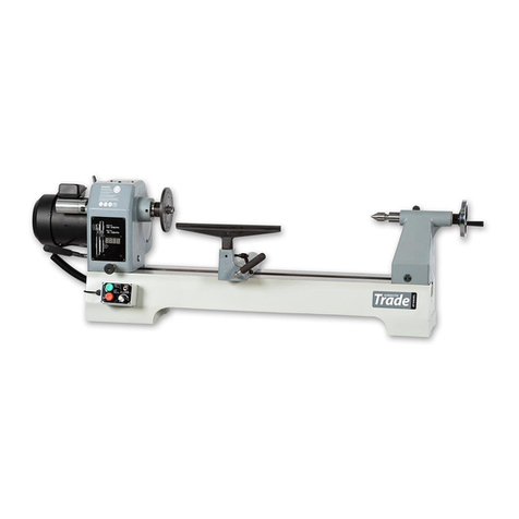
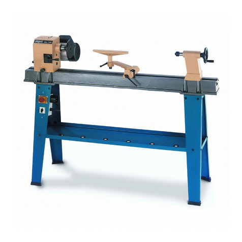
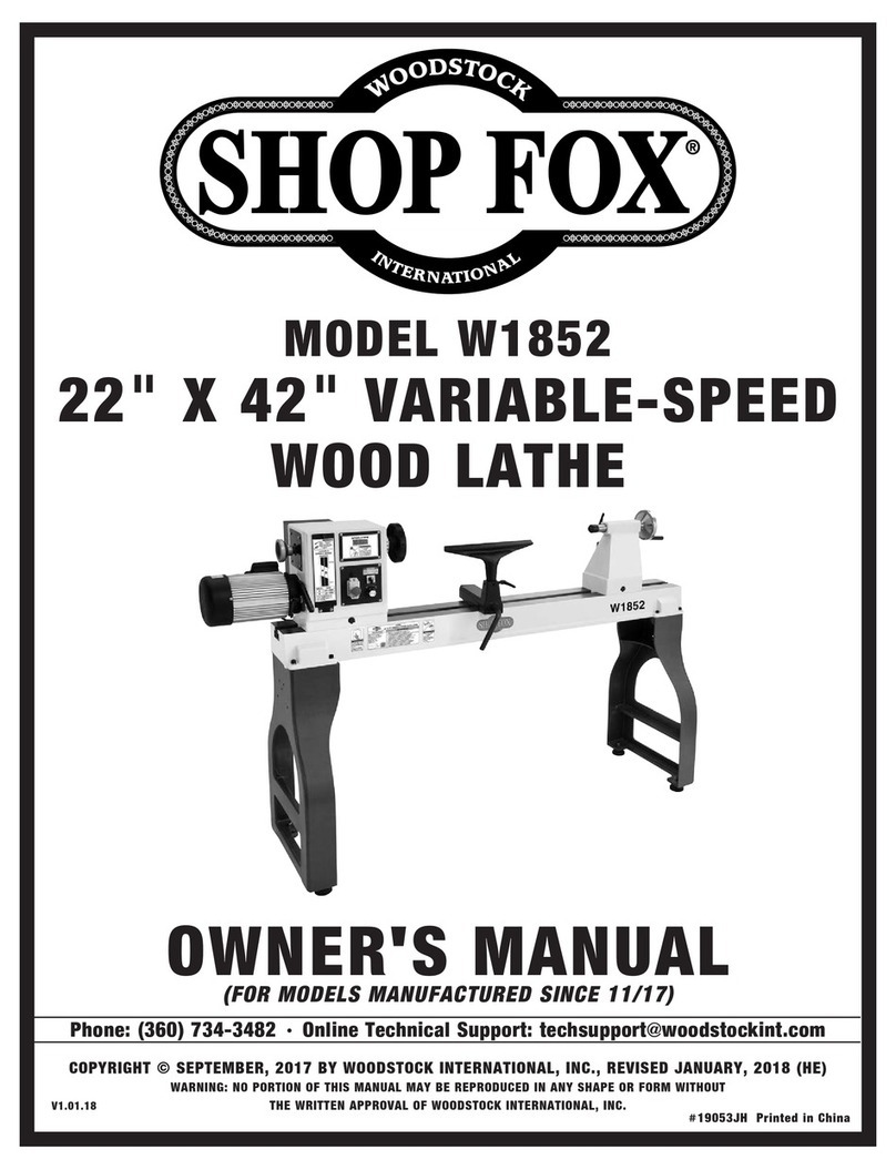
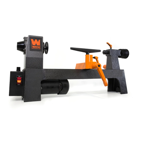
OTMT SC4 Instruction Manual

1
SC4BenchLathe
User sGuideandInstallationManual
Version date:02-09-11
PleaseRead ThisManualCarefully BeforeOperatingthisMachine.
Copyright by TraversToolCo., Inc., February2011
PDFcreated withpdfFactoryProtrialversion www.pdffactory.com

2
TableofContents
IMPORTANTSAFETYINSTRUCTIONS.............................................................................................4
LatheFeatures...................................................................................................................................5
Welcome............................................................................................................................................6
User Manual....................................................................................................................................6
CapabilitiesoftheLathe..................................................................................................................6
SettinguptheLathe..........................................................................................................................7
ElectricalRequirements...................................................................................................................7
Lifting theLathe...............................................................................................................................7
BenchMounting...............................................................................................................................8
MachineCleanup.............................................................................................................................8
OperatingControlsandFeatures.....................................................................................................9
Carriage Handwheel........................................................................................................................9
Cross-Feed Handwheel...................................................................................................................9
CompoundHandwheel....................................................................................................................9
Carriage Lock Screw......................................................................................................................10
Power Feed(Half-Nut)Lever.........................................................................................................10
X-YAutoFeedLever.....................................................................................................................10
Tailstock Handwheel......................................................................................................................11
Tailstock Quill Lock........................................................................................................................11
Tailstock Locking Handle...............................................................................................................11
Tailstock OffsetFeature.................................................................................................................11
ElectronicControls.........................................................................................................................12
ControlPanel.................................................................................................................................12
Setting theSpindleSpeed..............................................................................................................12
EmergencyStop Button.................................................................................................................12
Spindle DisengagementKnob........................................................................................................13
Tooling andAccessories................................................................................................................14
HighSpeed Steel Cutting Tools.....................................................................................................14
4-Jaw Independent Chuck.............................................................................................................14
Digital Caliper................................................................................................................................14
Center Drills...................................................................................................................................14
Tailstock ChuckandArbor.............................................................................................................15
DrillSets........................................................................................................................................16
EndMills........................................................................................................................................16
EyeProtection...............................................................................................................................16
CuttingFluid...................................................................................................................................17
InitialSafetyChecks........................................................................................................................18
RegularSafetyChecks EachTimeMachine is Used..................................................................18
Usingthe3-Jaw Chuck..................................................................................................................20
BasicLatheOperations..................................................................................................................22
StockPreparation..........................................................................................................................22
PDFcreated withpdfFactoryProtrialversion www.pdffactory.com

3
CuttingTool Selection....................................................................................................................22
Setting theTool Height..................................................................................................................23
QuickChangeTool Posts..............................................................................................................24
PositioningtheTool.......................................................................................................................24
Rotational SpeedSelection............................................................................................................25
Facing aWorkpiece.......................................................................................................................25
CleaningupaFacing Cut...............................................................................................................27
Facing withPowerFeed................................................................................................................27
Center DrillingaWorkpiece...........................................................................................................29
DrillingaWorkpiece.......................................................................................................................30
TurningaWorkpiece......................................................................................................................32
TurningwithPower Feed...............................................................................................................33
CuttingShort Tapers......................................................................................................................35
CuttingScrewThreads..................................................................................................................37
Setting UpaGear Train.................................................................................................................37
ThreadCuttingExercise................................................................................................................40
Maintenance....................................................................................................................................43
PeriodicLubrication.......................................................................................................................43
Bearing RaceLubrication...............................................................................................................43
BareMetalSurfaces......................................................................................................................43
Adjustingthe Gibs..........................................................................................................................43
Appendices......................................................................................................................................44
Appendix A Specifications...........................................................................................................44
Lathe..........................................................................................................................................44
MillingHeadAccessory..............................................................................................................44
Appendix B Parts Diagrams........................................................................................................45
AppendixC PartsList.................................................................................................................47
AppendixD CircuitDiagram........................................................................................................49
Appendix E PackingList.............................................................................................................50
PDFcreated withpdfFactoryProtrialversion www.pdffactory.com

4
IMPORTANTSAFETY INSTRUCTIONS
Commonsenseandcautionarefactorswhichcannotbebuiltintoanyproduct.Thesefactors
mustbe suppliedbythe operator.
PLEASEREMEMBER:
1.When usingelectrictools,machinesorequipment, basicsafetyprecautionsshould
alwaysbe followedtoreducethe riskoffire,electricshock, and personalinjury.
2.Keepworkarea clean. Cluttered areasinviteinjuries.
3.Considerworkarea conditions.Donotusemachinesorpowertoolsindamp,wetor
poorlylitlocations.Don notexposeequipmenttorain,keepworkareaswelllit.donot
usetoolsinthepresenceof flammablegasesorliquid.
4.Keepchildren away; allchildrenshouldbekept awayfromtheworkarea.
5.Guardagainstelectricshock.Preventbodycontactwithgroundedsurfacessuchas
pipes, radiators, rangesandrefrigeratorenclosures.
6.Stayalert. Neveroperateapowertoolif you aretired.
7.Donotoperatetheproduct ifundertheinfluenceofalcoholordrugs.Readwarninglabels
onprescriptionstodetermineif yourjudgmentorreflexesmight beimpaired.
8.Donotwearlooseclothingorjewelryastheycan becaughtinmovingparts.
9.Wearrestrictivehaircoveringtocontainlong hair.
10.Useeyeandearprotection.Alwayswear.
11.Keepproperfooting and balanceatalltimes.
12.Donotreachoveroracrossrunning machines.
Beforeoperations
1.BesurethepowerswitchisOFFwhen not inuseandbeforepluggingin.
2.Donotattempttouseinappropriateattachmentsinanattempttoexceedthetool’s
capacity.
3.Checkfordamaged partsbeforeusingthe machine.Anypartthatappearsdamaged
shouldbe carefullycheckedtodeterminethatitwilloperateproperlyand performits
intendedfunction.
4.Checkforalignmentandbindingofall movingparts,brokenpartsormountingfixtures
andanyotherconditionthatmayaffectproperoperation.Anypartthatisdamaged
shouldbe properlyrepairedorreplacedbyaqualifiedtechnician.
5.Donotusethemachineif anyswitchdoesnotturnoffproperly.
Operation
1.Neverforcethe machineorattachment todotheworkof alargerindustrialmachine.Itis
designedtodothejob betterandmoresafelyat therateforwhichitwasintended.
2.Alwaysunplugthe cordbytheplug.Neveryankthecordoutofthewall.
3.Alwaysturnoffthemachinebeforeunplugging.
PDFcreated withpdfFactoryProtrialversion www.pdffactory.com

5
Lathe Features
PDFcreated withpdfFactoryProtrialversion www.pdffactory.com

6
Welcome
Congratulationsonselecting theOTMTSC4
BenchLathe(SC4).You havechosena
precisionmachinetoolthatcan performawide
rangeof complexandpreciselatheoperations.
Withproper maintenanceand care,itwill
providemanyyearsofservice.Shouldyou
haveanyquestionsregardingtheoperationof
yourlathe,pleasecontact TraversTechnical
Support forassistance.
TechnicalSupport
(1-800-234-9985, press 4)
Fax: 718-661-5637
Email: tech@travers.com
UserManual
The purposeofthismanual istofamiliarizethe
lathe operator withthe installation andcontrols
ofthemachine and basic latheprocedures. To
becomeproficientin usingthe lathe,the
operator shouldseekin-depthtraining using
referencebooks,resourcesavailableonthe
Internet, training coursesatcommunity
technical schoolsor fromanoperator already
skilledinthe useofasimilarlathe.
Capabilities oftheLathe
Aprecisionmetal-working latheisone ofthe
mostusefulandproductivetoolsinthe
machine shop.Thelathe providesthe
capabilitytoproducecylindrical andtapered
shapeswithveryaccuratedimensionsin a
wide varietyofmaterialssuchassteel,brass,
aluminumandmanyplastics. Withappropriate
toolingitiseven possible tocreateround,
concaveandcubical shapesonthelathe.
TheSC4latheisequippedwithapowerful
1000-watt brushlessDCmotor withelectronic
speed control,providingstrong torqueatall
speeds,electronicbrakingand instant direction
reversalforoperationssuchastapping.The
motor iscompletelysealedfromdirt,dust,oil,
metal chipsandother shop contaminants and
ispermanentlylubricatedand maintenance-
free.
While theultimateprecisionofafinished
workpiecedependson manyfactors,suchas
the material,shapeofthe cutting tool,proper
adjustmentofthe lathe andskill ofthe lathe
operator,dimensionsofone-one-thousandthof
aninch(0.001”)or better arepossible.
Withtheprovidedsetofchange gears,power
feedratesmaybeadjustedand awiderange
ofbothmetricand SAE external and internal
threadscanaccuratelybecut.Theoptional
milling head accessory(Item#87-116-027)
addslightvertical milling andprecision drill
press capabilitiestothe SC4.
PDFcreated withpdfFactoryProtrialversion www.pdffactory.com

7
SettinguptheLathe
The SC4latheshouldbe locatedinawell-
lighted andwell-ventilatedareafreefrom
excessivehumidity or moisture thatcould
causerusting oftheprecisionmetal surfaces
or tooling.
ElectricalRequirements
TheSC4lathe configuredfor U.S.operation
usesstandard 120V AC60-cyclesingle-phase
powerand hasapeakcurrentdemandof12
amps.Whilea15-ampcircuitmaybesufficient
forpowering the lathe,a20-ampcircuitis
recommended.Thecircuitmustnotbe shared
withotherhigh-currentdevices,suchasan air
compressor,windowairconditioner or coffee
pot,thatmaybeoperating,orswitchon,while
thelatheisin use.Lowcurrentdevices,such
asaworklamp,maysharethe samecircuitas
thelathe.
Aplug-inpower failure emergencylight thatwill
automaticallyturnoninthe eventofapower
failure ortrippingofan overloadedcircuit
breakerisrecommendedforsafety. Inthe
eventthatpower tothelathe,or workspace
lighting,shouldbeinterruptedwhilethe latheis
inuse,theemergencylightwill enable the
operator tosafelyturnoffthepowerswitchto
thelatheand moveawayfromthelathe until
powerisrestored.Suitable lightsare available
atmosthardware and home-supply stores.
Care shouldbe takentoensureasafework
area withelectrical wiringandgrounding
approvedbylocal electrical codes. Thelathe
usesathree-prongelectrical plugtoprotect the
operator fromriskofshock or electrocution.
Thelathe must beplugged intoaproperly
grounded outlettoensuresafeoperation.Do
notattempttomodify theplugtofita2-prong
outletor extension cord byremovingthe
groundconductor or byusingan adaptor.
Doingsomayresultinshock or electrocution.
Ifitisnecessarytoplug thelatheintoan
extensioncord,theextension cord musthave
aproperly functioning 3-prongelectrical ground
plug and outlet,pluggedintoaproperly
grounded3-prong walloutlet.The extension
cordmusthaveatleast15 Ampsofcurrent-
carryingcapacity toavoidoverheatingthe cord,
whichcouldcauseariskoffire.Acordrated
for 20Ampsormoreisrecommended.Inno
caseshouldthe lengthoftheextension cord
exceed20feet.
Lifting theLathe
TheSC4lathe weighsapproximately275 lbs.
(125kg.)andmustbe mountedonastrong
tableor benchcapable ofsupporting 350 lbs.
or more.Ashopcranewithanylon liftingstrap
or othersuitablelifting apparatusshouldbe
usedtosafelylift themachineontothetable or
bench.
Shopcrane(Item # 96-004-166)
Using ashop cranetoliftthelathe
Properliftingtechniques(e.g.bendatthe
knees,notattheback)shouldbeused to
minimizeanyriskofpersonal injury. Consult
theInternetforinformationonproper lifting
techniques.
PDFcreated withpdfFactoryProtrialversion www.pdffactory.com

8
BenchMounting
For stabilityand safeoperationthelathemust
bebolted toasturdymachinestandor
workbenchcapable ofsafelysupporting at
least350lbs.Acarpentersormachinistslevel
should beusedtoverifythatthelathebedis
level.Largediametermetalfenderwashersor
shimsmaybe usedundermounting feetto
level thelathe.Sufficientclearancemustbe
providedontheleft sideofthelathe toallow
theaccess doortoswingopenandprovide
working room toadjust thegears
MachineCleanup
Thelatheis protectedfrom rust during shipping
byawaxy redgreasethatmustberemoved
beforeputting the machine touse.Thisisbest
doneusingdisposableshopragsand paint
brushestogether withasolventsuchas
keroseneorWD-40.Avoidsolventssuchas
paintthinnerthatmaydamagethepainted
surfacesofthelathe,andhighlyvolatile
solventssuchasacetone thatpresentafire
andinhalation hazard.
Goodventilationmustbe provided when
solventsareusedand caremust betakento
avoidopen flames,smoking materialsor
electrical sparksthat could ignitesolventfumes.
Care shouldbetakentocleantheshipping
greasefromallmoving parts,includingparts
thatmaybehiddenfromview,suchas
leadscrewsunder thecross-slide and
compound slide.
PDFcreated withpdfFactoryProtrialversion www.pdffactory.com

9
OperatingControlsandFeatures
CarriageHandwheel
Thecarriagehandwheel movesthecarriage
backandforthalongthe ways.Turningthe
handwheel clockwisemovesthe carriage
towardsthetailstock;turningitcounter-
clockwisemovesthe carriagetowardsthe
headstock.
CarriageHandwheel
Whenthe carriage ismoved bypowerfeed,
thecarriagehandwheel maybedisengagedby
pulling ittowardsthe operator.Thisprevents
thehandwheel fromrapidlyrotatingand
causing apotential hazard.Tore-engagethe
handwheel,pressitinwardswhileslowly
rotatingituntilthegearsengage.
CarriageHandwheelDisengaged
Cross-FeedHandwheel
Thecross-feed handwheel (alsoknownasthe
cross-slidehandwheelorcross-feed) advances
or retracts thecarriageacrosstheways.This
motion maycontrol thedepthofacutfor a
turningor boringoperation ormayadvancethe
cuttingtool across the faceofaworkpieceina
facingoperation.
Cross-FeedHandwheel
Compound Handwheel
Thecompoundhandwheel(alsoknownasthe
compoundfeed) advancesorretracts the
toolpostalongtheangleatwhichthe
compoundis setasindicatedbythe protractor.
Thecompoundhandwheeltypicallyisusedfor
makingshorttaperedcuts, limitedbytherange
ofmotion ofthecompound slide,andfor
threadcutting operations.
Boththe cross-slide andcompound
handwheelshavegraduatedcollarsthatcan
be usedtomeasurethemovementofthe
cuttingtool towardsorawayfromthe
workpiece.Bygraspingthegraduateddial
whileholdingthehandwheelsteady, the
graduateddial canbe settoazero readingto
facilitatemakingacuttoaspecific depth.
CalibratedHandwheelDial
PDFcreated withpdfFactoryProtrialversion www.pdffactory.com

10
CarriageLockScrew
For certainoperationssuchasfacing,inwhich
thetoolisadvanced across the faceofthe
workbythe cross-feed handwheel,itisgood
practicetolockthecarriagetothewaysto
preventthecarriage frommovingduringthe
cut.If thecarriageweretomoveduringa
facingcut,theresultwouldbeaslightly
concaveorconvexcone-shaperatherthana
perfectlyflatsurfaceon theend ofthe
workpiece.
Lockingthecarriage
Thecarriageislocked byturning the carriage
lock screwclockwiseusinga5mm hexwrench.
When the lockingscrewisused for thefirst
timeitmaybe inthelockedposition as
shippedfromthefactorytopreventthe
carriagefromshifting position duringshipment.
Alwayschecktomakesurethatthe locking
screwisunlockedbefore attemptingtomove
thecarriage withthecarriagehandwheelor
powerfeed.
PowerFeed(Half-Nut)Lever
ThePowerFeedLever,alsoknownasthe
Half-NutLever,islocatedontherightsideof
theapron atthe frontofthelathe,nexttothe
carriagehandwheel.Itisused todrivethe
carriage under power forturningandthreading
operations.
PowerFeed(Half-Nut)Lever
Whenturnedabout45degreestotheright, it
clampsapairof “half-nuts”around thethread
ofthelead screw.If the leadscrewisengaged
and rotating,the carriagewill bemovedalong
the waysunder power fromtheleadscrew.
Before engaging the Power Feed Lever,
ensure thatthe carriageisnotlockedtothe
ways by theCarriageLock Screw.
When thespindleisrotatingintheForward
direction,thecarriageismovedtowardsthe
headstock.Withthe spindlerotatinginthe
Reversedirection,thecarriage movesaway
fromthe headstock.Movingthelever backto
the vertical position disengagesthehalf-nuts
fromthe leadscrewandstopsthe motionofthe
carriage.
X-YAutoFeedLever
Locatedonthe rightside oftheapron,nextto
the PowerFeedLever,theX-Y AutoFeed
Lever controlsthemotionofthecarriagewhen
usedwiththeoptionalmilling head accessory,
butcanalsobe used for latheoperations.
When using theX-Y AutoFeed Lever,the
Power Feedlevermust bedisengaged.
PDFcreated withpdfFactoryProtrialversion www.pdffactory.com

11
X-Y AutoFeedLever
Inthelower position,theX-YAutoFeedlever
movesthecarriagealong theways, muchlike
thePower Feedlever,butataslowerspeed.
Thisfeature isuseful for makingfinefinishing
cutsusing powerfeed.
Inthe upper positionitfunctionsasapower
cross-feedcontrol and movesthecross slide
away fromthe operator towardstheback of the
lathe.When themotor isreversed,thepower
crossfeedmovesthecross slide towardsthe
operator.Inthecenter, “0”orneutral position,
thefeedis disengaged.
TailstockHandwheel
Rotatingthetailstockhandwheel movesthe
tailstockquill (alsoknownasthetailstockram)
inand outofthetailstock.Thisfeature isused
duringdrillingoperationsandwhen acenteris
used inthetailstocktosupport longstock.
TailstockQuill Lock
Whenthetailstockisusedinstationary
operations,as whensupportingtheendof long
stock,thequillmaybe lockedin placeusing
thetailstock quilllock.Aquarter turnofthe
handleissufficienttolock orunlock thequill.
TailstockLockingHandle
Thetailstock lockinghandle ontherear ofthe
tailstocklocksthe tailstockatanylocation
alongtheways.Thetailstockislockedby
pulling thelever towardstheoperator and
releasedbypushingthelever awayfromthe
operator.If necessary, the clampingaction
may beadjustedbyremovingthetailstockfrom
the endofthelathewaysandadjustingthe
lockingnut on theundersideofthetailstock.
Astopscrewlocatedbetweentheways atthe
rightend ofthelathepreventsthetailstock
fromfallingofftheendofthelathe.Thisscrew
mustberemovedbeforeslidingthe tailstock off
theendoftheways for adjustment.
Tailstock Offset Feature
Toturn longtaperson aworkpiecemounted
betweencenters,the tailstockmaybeoffset
horizontallyfromthe lathecenterline.Tooffset
the tailstock,loosenthetwosmallsetscrews
belowthe camleverontherightsideofthe
tailstock, thenloosenthe twosetscrews onthe
front and back sidesofthe tailstock.
TailstockOffsetIndicator
Thetwoscrewsonthefrontandbackofthe
tailstockworkinoppositiontoeachother to
offsetthetailstock;asonescrewistightened
the othermustbeloosened by acorresponding
amount.Theamountofoffsetmaybegauged
byobservingthe offsetindicator guideon the
rightendof thetailstock.
Aftercompleting thetaper operation,the
tailstockisrestoredtoitsnormalpositionatthe
horizontal centerline.Accuratealignmentusing
atest bar anddialindicatoris recommended.
PDFcreated withpdfFactoryProtrialversion www.pdffactory.com

12
ElectronicControls
Themain power switchfor the latheisthe red
rockerswitchlocatedonthe controlpanel.A
greenpilotlampilluminates whenthe poweris
on.Afuseholderabovethepilotlampcontains
areplaceable20Ampfusetoprotectthelathe
fromelectrical overloads.
ControlPanel
ControlPanel
Asoft-touchpanel ofbuttonscontrolsthelathe
spindlespeedanddirection:
é-IncreasespindleRPM speed
ê-decreasespindle RPM speed
Start start thespindle motor
Psetspindle toforwardrotational
direction
Qsetspindle toreverserotational
direction
Stop stopthe spindle motor
Setting theSpindleSpeed
Tostartthe spindlerotation,press the Start
button.Thecurrentspindle rotationalspeed
and direction (FORor REV)are displayed on
thedigital display.
Spindle-speedtachometer
When the lathe ispowered onorthe
EmergencyStop buttonisreset, the display
willmomentarilydisplay8888,thenwill display
0000.
Toincreasethe speedofspindlerotation,
depressand holddownthe ébutton.To
decreasespindlespeed,depressand hold
downthe êbutton.Smallincrementalchanges
tothe spindlespeedmaybemadeby
momentarilypressingthebuttons.Tostopthe
spindlerotation,pressthe Stop button.
Thefirsttimethatthe Start buttonispressed
after turning onthe power tothe lathe,ofafter
resetting the Emergency Stop button,the
spindlewillbeginturningatitsslowestspeed,
about100RPM.
Whenthe operatingspeedisadjustedtoa
higher RPM,thenewspeed issaved when the
Stop buttonispressed.When Start ispressed
again,the lathe will resumeoperating atthe
savedspeed.Thesavedspeediscleared
whenthelathe ispoweredoff orthe
EmergencyStop button ispressed.
EmergencyStopButton
Locatedbelowthe Start button,the red
EmergencyStop buttonisused toquickly
stop the spindleinthe eventofanemergency,
PDFcreated withpdfFactoryProtrialversion www.pdffactory.com

13
suchasaworkpieceworking loosefromthe
chuck.
EmergencyStop button
Pressing the EmergencyStop buttonfirmly
withtheheel ofthe hand will bring thespindle
toastopandkeepthe lathe fromrestarting
untilthe EmergencyStop button isresetby
rotatingthe knurledrimofthe button in a
clockwisedirection.
Pressing the Start button,or anyothercontrol
on thepanel,willhavenoeffectuntil the
Emergency Stop buttonisreset.Whenthe
Emergency Stop buttonisreset, the spindle
speed willalsoberesettothe minimum speed
ofabout100RPM.
SpindleDisengagementKnob
Thelargesilverknobtotherightofthe
Emergency Stop buttonengagesand
disengagesthe spindlefromthe motordrive
whilestillallowing theleadscrewtoturnand
movethecarriageunderpowerfromthegear
train.
SpindleDisengagementKnob
When performingmilling operationsusingthe
milling headaccessory(Item #87-116-027)the
spindleshouldbedisengaged for safetysothat
therotating chuckdoesnot poseahazard.
Withthe lathe stopped,turn theknob tothe
rightabout ¼turntodisengagethe spindle.To
re-engage it, rotatethe knobtothe leftwhile
alsoturningthechuckbyhand toallowthe
gearsinsidetheheadtomesh.The knob
shouldnotbemovedwhilethemotoris
running.
PDFcreated withpdfFactoryProtrialversion www.pdffactory.com

14
ToolingandAccessories
Operationofthelathe requirescertainbasic
necessitiessuchascuttingtools.Optional
accessoriessuchasa4-jawchuckand milling
headextendthecapabilitiesofthe latheto
performadvancedtypesofwork.Safetygear,
suchassafety glassesandeyeshieldshelp to
protect thelatheoperator.
Thissectiondescribessomeuseful
accessoriesandtoolingfor theSC4lathe.
HighSpeedSteelCuttingTools
For the homemachinistandlightindustrial
userofthe lathe,High SpeedSteel (HSS)
cutting toolsareused for most cutting
operations. Along withfinishedversions,these
toolscanbepurchasedasblanksandground
tothe desired cutting shape using abench
grinder.
SetofHSS cutting bits
Item# 22-501-102
Aside fromlowcost,themainbenefitofHSS
toolsisthatspecialized toolshapescan be
groundasneededforoperationssuchas
chamfering, material cut-off andboring.
4-JawIndependentChuck
A4-jawchuck can holdstockwithasquareor
rectangular cross-sectioninaddition toround
andoctagonal stock.Unlikethestandard3-jaw
chuck,inwhichallofthejawsmovetogether,
onthe4-jawchuckthejawsadjust
independently,enabling themtoclamp
irregularly-shapedstock.
4-JawChuck
Item# 87-116-026
Adjustingthe jaws individuallymakesit
possible tocenter aroundworkpiece,ora
referencepointon anirregularworkpiece,with
greatprecision.Thisfeature isuseful whena
workpiecehasfeatureson oppositeendsthat
mustbemachinedonexactlythe sameaxis.
Offsettingtheworkpiecealsomakesitpossible
todrill off-centerholesandtoturncam lobes.
Digital Caliper
Digital calipersare convenientmeasuring
toolsfor manylatheoperations. Theymeasure
outsideandinsidediametersaswellashole
depthstoaresolution of0.0005”.Theyswitch
instantlybetween metricandinchunits,soyou
workin either format.
DigitalCaliper
Item#57-016-060
CenterDrills
Centerdrills,alsoknownasadrill&
countersink,are shortand stiffandtherefore
donotflex.
PDFcreated withpdfFactoryProtrialversion www.pdffactory.com

15
Standard-lengthdrillsmayflexandwandera
small amountwhentheyfirst starttopenetrate
thesurfaceofthework. Theflexingmaycause
thestartingpointtobe off-center andtherefore
thedrilledholemaybeoff-centerandnot
perfectlyparallel totheaxisofthe workpiece.
Therefore,itrecommended alwaystousea
centerdrilltostartadrilledhole
CenterDrill
Center drillsare availablein manysizesand
made ofvariousmaterials,muchlikedrill bits.
For workon theSC4,asetof5HSScenter
drills, #1through#5 insize,will meetmost of
theneeds theoperatoris likelytoencounter.
SetoffiveCenterDrills
Item # 01-095-000
TailstockChuckandArbor
For mostdrillingoperations,the drill bitisheld
inaJacobs-typechuckmountedinthe
tailstockby meansof a#2 MorseTaperarbor.
Jacobs-stylechuck
Item# 63-100-004
Sincethechuckandthearbor arepurchased
separately,care must betakenthatthefront
taperofthearborthatmateswiththechuckis
thepropersizeforthechuck.
Chucks foruseon alatheusuallyhavea
femaleJacobsTaper,soanarbor isneeded
witha#2MorseTaperononeend anda
JacobsTaper matchingthe chucktaperonthe
otherend.
Arbor for tailstock chuck
Item# 63-004-821
Arbors, suchasthe oneinthephotograph,
oftenhaveaflattang attheend oftheMorse
Taper,usedtodrivethe arbor insometypesof
machinery.For usein the SC4tailstock,the
tangneedstobecutoffusing ahacksaw,
metal-cutting bandsaw orabrasivecutoff wheel.
PartoftheMorseTaper mayalsoneed tobe
cutoff in orderforthearbortofitproperly in the
tailstock bore.
Thechuckgenerallyispermanentlymounted
tothearbor.Todo this,first wipe theJT endof
the arborandthecorrespondingJT taper in the
end ofthe chuckwithacleanshoprag to
removeanyoil,grease,chipsorgrit.Itis
importantthatbothmatingsurfacesbe free
fromanycontaminationtoensureatight,
securefit.Insertthe JTtaper endlooselyinto
the chucktaper,thenrap theoppositeendof
thearborfirmlyon aboard todrivethetapered
PDFcreated withpdfFactoryProtrialversion www.pdffactory.com

16
endsharplyintothechuck.The arborshould
nowbetightlycoupledtothechuck.
When mounting the arbor in the tailstock taper,
again,bothtapers shouldbe freefromanyoil,
greaseorgrittoensureatightcoupling.Hold
thechuckinone hand,thensnapitrapidlyinto
thetailstock tapertoensure thatthetapers
lock securely together.
The tailstockchuckarbor isremovedfromthe
tailstockbyrotatingthetailstockhandwheel
counterclockwiseuntil thearbor isforced out.
Whencuttingofftheexcess endofthearbor,
caremustbetaken toensurethatitisnotcut
tooshort, or itwillnotbelongenoughtobe
forcedout ofthetailstockforremoval.
DrillSets
Drill setsin inch,metricand number and letter
sizeswill provideagreatrangeofcapabilities
when using thelatheasaprecisiondrillpress.
Inch-sizeDrill Sets
EndMills
Endmillsarethe mostcommonlyusedcutting
toolsfor millingoperationswhenusing the
optionalmillingheadaccessory(Item#87-
116-027).
Endmillsareavailable inawiderange ofsizes,
configurationsandmaterialsspecializedfor
differenttypesofwork.For general use,aset
of2- and 4-flute,high-speed-steel (HSS) is
convenienttostartwith,asitwill handlemany
basicoperations.
Setof2-and4-fluteendmills
(Item# 09-335-905)
EyeProtection
Lathesproducehotandsharpmetal chips that
canflyoutfromthecuttingarea athigh speed
toadistanceof24inchesor more.Always
wearappropriateindustrial-qualitysafety
glassesor faceshieldswhenoperatingthe
lathe.Safetyshieldsattachedtothemachine
or heldbyamagneticbasemayalsobe used
together witheyeprotection for additional
safety.
Safetyglasses
Item# 96-085-300
Faceshield
Item# 97-000-794
PDFcreated withpdfFactoryProtrialversion www.pdffactory.com

17
Safetyshield
Item # 99-003-525
Cutting Fluid
For manylatheoperations,cuttingfluidisused
toreducefrictionand improvechipclearance.
Proper useofcuttingoil willextend toollife,
reducestress onthelatheandimprovethe
qualityofthecut surface.Modern cuttingfluids
are speciallyformulatedfor specificmetalsand
operations. For most lathework,ageneral-
purposecutting fluidsuchasTap-Magicor
Tapmaticis appropriate.
TapMagicCutting Oil
Item # 81-002-914
TapmaticCuttingFluid
Item# 81-007-050
When machiningaluminum,aspecially
formulatedcuttingfluidsuchasTap-Magic
Aluminumwillgivesuperior results.Ithelps
preventchipsfromwelding tothecuttingedges
ofthetool acommonproblemwhen
machining aluminum.
TapMagicAluminum
Item# 81-002-928
PDFcreated withpdfFactoryProtrialversion www.pdffactory.com

18
InitialSafetyChecks
Before thelatheisusedfor anymachining
operations, itshouldbecheckedforproper
operation.
•Usethehandwheelstomovethecarriage,
cross-slideandcompoundthroughtheirfull
rangeofmotion.
•Turn the chuckbyhandthrough afewfull
turns.Ensurethatthegearsinthegear
trainontheleftsideofthelathe areturning
smoothly. Verify thateverythingismoving
freelywithoutbinding or excessive
resistance.
•Ifthechuck isinstalled inthespindle,
ensure that all oftheretaining nutsaretight
andthatthechuck keyhasbeenremoved.
•Turn onthe redpower switch.Thedigital
tachometer shoulddisplay0000andthe
sound ofthe coolingfan shouldbe heard.
•Ensurethatthecuttingtoolisclear ofthe
chuck,thenlower the chucksafetyshield.
Thelathewill not startwiththesafety shield
intheraisedposition.
•Pressthegreen START buttontostartthe
spindlerotation.
•Usethe éand êbuttonstogradually
increasethespindlespeed fromslowto
high speed and back toslowspeedagain
toverify thatthe speedcontrolsare
functioningproperlyandthatthespindle
turnsfreely.
Ifanyunusual noisesor otherunexpected
events occur,contact TraversTechnical
Support forassistance.
TechnicalSupport
(1-800-234-9985, press 4)
Fax: 718-661-5637
Email: tech@travers.com
RegularSafety Checks EachTime
MachineisUsed
Before beginning anycuttingoperation:
•Alwayswear industrial-qualitysafety
glassesoruseasafety faceshieldwhen
operating thelathe.
•Makesurethatthechuckkeyhasbeen
removedfromthechuck.
•Clear awayanystrandsofmaterial that
maybeleft fromprior operationsfromthe
area ofthechuck.
•Loosematerial could becomeentangledin
the chuck or theworkpieceand posea
hazard.
•Lowerthechucksafetyshieldover the
chuck. Themotor willnotstartwiththe
guard intheraisedposition.
•Be surethattheworkissecurelyheldin
thechuckjaws and notmounted ata
skewed angle.Grasptheendofthe
workpieceandattempttomoveit make
surethatitisnot loose.
•Verify thatthecuttingtool andanyother
objectsareclearofthechuckandthe
workpiecebeforestartingthelathe.
•Clear theworkareaofanyobjects that
couldcauseyoutriporslip;alsoanytools
or other objectsonornearthelathethat
are notrequiredfor thecurrentoperation.
•Avoidloosesleevesorlooselyfittingshirts
thatcouldbecomeentangledin rotating
parts. Removeor secure necklacesand
otherjewelry.
•Tiebacklonghairtoavoidgettingit
entangledin the rotating chuckand
workpiece.
•Userecommended cutting fluidstoreduce
theforcerequired bythecutting tool.This
willhelp keepthetool cooler andincrease
itslife, andwillmakeit less likelythatchips
willweld tothetool orworkpiececausing
rough surfacefinishes.
PDFcreated withpdfFactoryProtrialversion www.pdffactory.com

19
•Neverreachover or acrossthe area ofthe
rotatingchuckor cutting tool.
•Neverattempttoremovestrandsof
materialwhilethechuckisrotating.Stop
thelathe,thenuseplierstoremoveany
excessmaterialthatcouldposeahazard
or obstruct theview ofthe work.
•Before removingthe workpiecefromthe
chuck,movethecuttingtoolawayfromthe
workpiece.Thesharptipofthe cutting tool
couldcutyou.
•Be careful whenremovingworkthathas
justbeenmachined. Boththeworkand the
tool used tocutitmaybe veryhotfromthe
frictional forcesofcutting.
PDFcreated withpdfFactoryProtrialversion www.pdffactory.com

20
Using the3-JawChuck
A5-inch3-jaw chuckisincludedwiththelathe.
Thechuckattachestothe spindlebythree
studsthreadedintothebackofthechuck
whichpass throughcorresponding holesin the
spindleplateandarelockedin placebynuts.
Alwaysensurestuds areproperly threaded into
thebackofthechuckbefore mountingthe
chuckonthespindle.Before startingthe lathe,
verify thatthenutsholding thechuckon the
spindlearesecurely tightened.
3-JawChuck
Thejawsofthe chuck areopenedor closedby
inserting the squareendofthe chuckkeyinto
anyoneofthethree keyslotsandrotatingthe
keyclockwisetotightenthejawsor counter-
clockwisetoloosenthejaws.Aspring isfixed
tothe end ofthekeytopreventthe keyfrom
beingleft inthechuck,whichwouldposea
safetyhazard.
Chuck key withsafetyspring
Asafetyshield ismountedabovethechuck to
ensure thatthe chuck keyisremoved fromthe
chuckbefore startingthe lathe.When the
safetyshield isinthe raisedposition,an
electricalinterlockswitchprevents the lathe
from starting.
Chuck SafetyShield
Thestandardjaws mountedinthe chuck when
itisshippedfromthefactorycan gripa
cylindrical workpiece.Thejawscan alsogrip
shorttubularstockbyexpandingthemoutward
togripthe insidediameter ofthe tubing.Since
thegrippingsurfaceisnotverylarge,this
procedureshouldbe restrictedtorigid-wall
tubingnolongerthan 4”inlength.
Asecondsetofjaws shipped withthechuck
cangrip the outsidediameter oflarger
diameterstock thancan begrippedbythe
standardjaws.Thesearecalledexternaljaws.
Removethe standard jaws byrotating the
chuck keycounter-clockwiseuntilthejaws
drop outoftheir slots inthechuck.Placea
shopragonthe waysbelowthechuckto
preventthe jawsfromdroppingonanddenting
theways.
External chuckjaws
Wheninstallingthe external jaws, or re-
installingthe standardjaws,the jawsare
individuallynumbered1,2and 3andmustbe
installedin thatsequence.Thenumbers
PDFcreated withpdfFactoryProtrialversion www.pdffactory.com
Table of contents

