ADJUSTMENTS & OPERATION
Feed and Thread Selection
To set the desired feed rate and thread selection, look at the charts in
Fig’s.3 & 6 and determine the feed rate desired in relation to the thread to
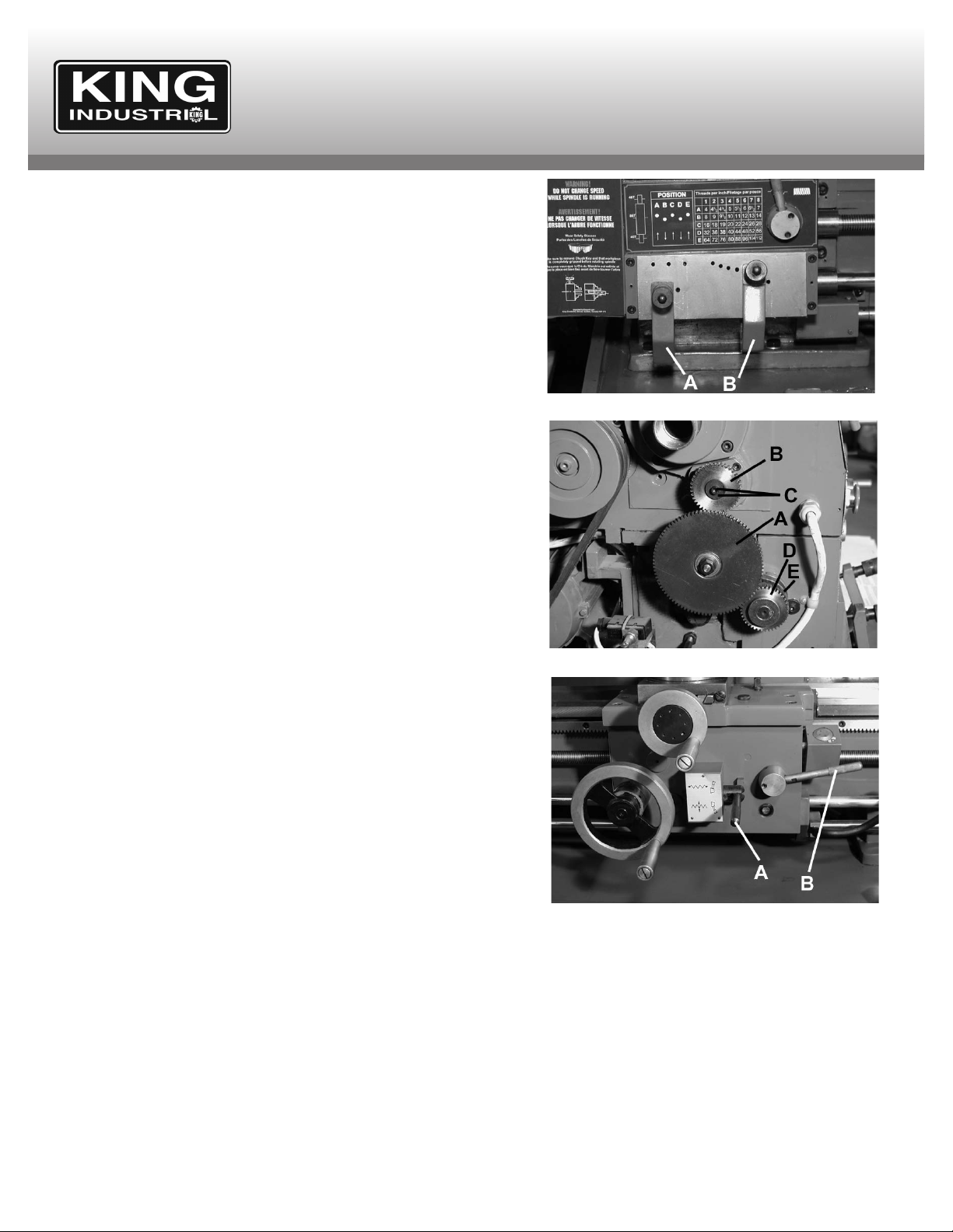
be cut. Once you have determined the job at hand, place the shifter levers
(A & B) Fig.15 in the appropriate positions.
If you desire Metric Threads, the mm change gears must be installed as
shown in chart Fig.5 and as described below.
Metric change gears
To obtain metric threads the proper metric change gears must be installed
inside the left side cover. Remove the 2 lock nuts which hold the left side
cover to the headstock and then remove the side cover. The large middle
gear (A) Fig.16 is the only gear which does not get interchanged. The
bottom gear (D) gets replaced with the 60T gear. The top gear (B) can be
replaced by the 26T, 27T, 35T, 45T & 50T, the top gear determines the
threads per mm.
Before changing gears, determine the threads per mm desired and look at
which gear configuration is needed. See “Metric Change Gear” chart Fig.5
as reference. To replace the top gear (B), remove cap screw and washer
(C) which hold it in place. Replace with appropriate gear and secure with
cap screw and washer. To replace the bottom gear (D), remove gear set
screw (E). Replace with 60T gear and secure it to the shaft using the same
set screw (E) removed previously. Make sure the shaft key is in place
between the gear and the shaft securing gear with set screw. Once the
change gears are in place, place the side cover and lock it using the same
lock nuts remove previously.
Automatic Power Feed- Longitudinal or Cross Feed
The power feed lever (A) Fig.17 is used to engage either the longitudinal
or cross feed. This lever has a safety interlock to prevent accidental
engagement of the half nuts when the lathe is in feed mode. There are 3
positions; the upper position engages the power longitudinal feed, the
lower position engages the power cross feed and the center position is the
disengaged position.
Make sure the correct gear configuration is set as shown in “Feed Rate”
chart Fig.3. Place the feed/thread selector to ANY position and make sure
the thread cutting engagement lever (B) is disengaged before operating.
Thread Cutting Operation
In order to obtain the desired thread, all change gears must be installed in
accordance to the thread charts. Failure to do so will give incorrect
threads.
Move the thread cutting engagement lever (B) Fig.17 downwards, this will
make it engage with the leadscrew for longitudinal travel of the carriage.
Make sure the power feed lever (A) is disengaged (in neutral position)
before operating the thread cutting engagement lever (B), note: a safety
interlock prevents accidental engagement of the half nuts when the lathe
is in feed mode.
FIGURE 15
FIGURE 16
FIGURE 17
Thread Cutting Dial Operation
The thread cutting dial is used to engage the half nuts with the
leadscrew in the same thread that has been previously cut.
Please note: Use any line of the dial for even pitches of threads,
but for odd pitches of threads you must use the same starting
line.
Example: When cutting a shaft with 10 T.P.I., engage the half
nuts at any number on the thread dial, when creating an odd
pitch, if you start the cut using 1 or a 3, continue to use the 1 or
the 3 until the thread is finished. See Fig.7.