CTI USB-Mini Series User manual
USB-485-MINI/OP
USB-422-MINI/OP
USB-485-MINI/R
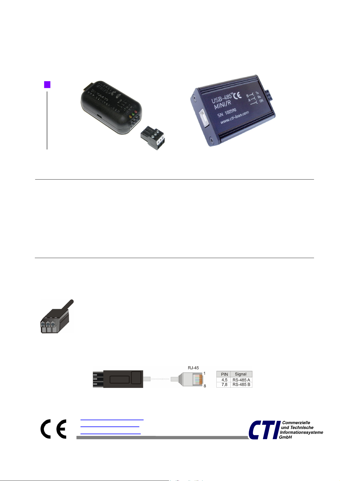
- Konverter
- steckbare Schraubklemme
- USB-Kabel
- CD mit USB-Treiber
Lieferumfang
Shipment
- converter
- pluggable locking ring
- USB-cord
- CD with USB-driver
Optionales Zubehör (nicht im Lieferumfang enthalten)
Optional Accessories (not contained in the shipment)
Steckergehäuse mit Zugentlastung für RS-485-
Schraubklemme
a case with pulling relief for the RS-485 locking ring
Anschlusskabel zur Verbindung mit RJ-45 Buchsen
a connection cord with RJ-45 plugs
office@cti
-
lean.com
www.cti-lean.com made in Germany
www.cti-shop.com
USB-Mini
Handbuch Konverterfamilie
Manual Converter family

USB-Mini Handbuch Konverterfamilie
Seite/Page 2
Anschluss an den USB-Port Connection to the USB-interface
Das Gerät wird mit dem
beiliegenden USB-
Verbindungskabel an einen USB-
Port Ihres PC angeschlossen.
Nach dem Anstecken leuchtet die
gelbe LED. Bei erstmaliger
Nutzung fordert Sie Ihr PC zum
Einlegen der USB-Treiber-CD auf.
Folgen Sie den Anweisungen auf
dem Bildschirm. Bei Bedarf finden
Sie auf der CD
Installationsbeschreibungen.
Nutzen Sie diese bitte auch bei
Fragen zur Deinstallation.
The device is connected with the
enclosed USB-connection cord to a
USB port of your PC. After the
connection is made, the yellow power
led lights up. At first use, the PC
asks you to insert the USB-Driver-
CD. Follow the instructions on the
screen. If necessary you can find
detailed installation instructions on
CD
Check that also about uninstallation.
Anschluss an den RS-
485-Bus
Connection to the RS-485-Bus
A und B-Leitung des RS-485-Bus
an der Schraubklemme
anklemmen und diese in den
Schnittstellenkonverter stecken.
Connect A and B-wires of the RS-
485-Bus to the locking ring and
insert it into the interface converter.
Belegung der Schraubklemme:
PIN
Signal
X Ground
A RS-485-Bus A
B RS-485-Bus B
USB-Mini Handbuch Konverterfamilie
Seite/Page 3
Konfiguration/Configuration
Jumper Einstellungen/
jumper settings
Blauer Jumper (Echo ein/aus) Blue jumper (Echo on/off)
Ist der Jumper gesteckt, wird ein
Echo erzeugt. Jedes gesendete
Zeichen, wird dabei automatisch
als Echo wieder empfangen. Einige
Protokolle prüfen damit, ob die
Daten korrekt gesendet wurden.
Voreingestellt: „ohne Echo“.
An Echo is created upon plugging
the jumper in. Any bit sent will
automatically be received as an
Echo. Several protocols check in
this way the correctness of data
transmission.
Default: „Echo off“.
Rote Jumper (Zuschaltbare
Abschlusswiderstände)
Red jumper (Optional resistors
for bus termination)
Bei einem RS-485-Bus erfolgt im
Allgemeinen eine Terminierung an
beiden Busenden. Wenn das Gerät
am Ende eines RS-485-Bus
eingesetzt wird, sollten die 3 roten
Jumper gesetzt sein.
Bei gesteckten Jumpern sind die
Abschlusswiderstände
zugeschaltet.
Es sollten entweder alle 3 Jumper
gesteckt oder alle 3 offen sein.
Werte der Widerstände:
2 x 390Ohm 1 x 220Ohm
Voreingestellt: „mit
Abschlusswiderständen“.
In general, both ends of a RS-485
bus have to be terminated. If the
device itself terminates a RS485
bus all three red jumpers have to
be plugged in.
Plugging in the jumpers connects
the bus with the resistors for bus
termination. All three jumpers
should be jointly plugged either in
or out.
Resistors: 2 x 390Ohm 1 x 220Ohm
Default: „Resistors connected“.
Rote/
red
Jumper :
Abschlusswiderstand/
Termination resistors
Blauer/blue Jumper:
Echo ein/aus
Echo on/off

USB-Mini Handbuch Konverterfamilie
Seite/Page 4
Technische Daten Technical data
Gemeinsame Eigenschaften Common characteristics
RS-485 2-Draht bis 32 Bus-
Teilnehmer
RS-485 2-wire up to 32 Bus-
participants
RS-485 maximale Datenrate: 3
Mbit/s (stückgeprüft)
RS-485 max. data rate: 3Mbit/s
RS-485 maximale Leitungslänge
1200 m (bei 9600 MBit/s)
RS-485 max. cable length 1200m
(at 9600 bit/s)
RS-485 Anschluss als
Schraubklemme
RS-485-connection as locking ring
Stromversorgung einfach durch
USB
Easy USB Power supplied
Konfigurierbar: Echo,
Endwiderstände
Configurable: Echo, termination
resistors
Status-LED Gelb:Power,
Grün/Rot:Rx/Tx
Status-LED yellow: Power,
green/red: Rx/Tx
USB-Treiber für alle Micosoft
Betriebssysteme ab XP
Linux ab Kernel 2.4.18
USB-driver for all Microsoft systems
since XP
Linux since Kernel 2.4.18
Spezielle Eigenschaften Special characteristics
Konverter
Converter
* optoentkoppelt
* optodecoupled
Stromaufnahme
power supply
Gehäuse
case
USB-Mini/OP 3000 V 95 mA Plastic 24x31x56
USB-Mini/R 2500 V 95 mA Alu 24x41x56
* schützt angeschlossene Geräte vor Überspannungen, (z.B. bei Blitzschlag)
* protects attached devices against overvoltages, (i.e. lightning)

Öffnen des Gehäuses beim USB-Mini
Opening of the casing for the USB-Mini
Hebeln Sie, wie in der
Abbildung zu sehen,
das Gerät mit einem
kleinen
Schraubendreher an
beiden Einkerbungen
vorsichtig auf. Danach
nehmen Sie den Deckel
ab.
Carefully lever up the
device at both grooves
using a small screw
driver. Remove the top
cover carefully.
Schließen des Gehäuses
Closing the housing
Wie die Abbildung zeigt,
setzen Sie den
Gehäusedeckel zuerst
an den Leuchtdioden
auf.
Drücken Sie danach das
Gehäuse vorsichtig
zusammen.
Start fastening the top
cover on the edge closer
to the LEDs. Then fit the
top cover onto the
bottom cover with slight
power.
Öffnen des Gehäuses beim USB-Mini/R
Opening of the casing for the USB-Mini/R
Lösen Sie auf jeder
der Stirnseiten die
jeweils untere
Schraube. Es
genügt je Seite nur
eine Schraube zu
lösen. Anschließend
lässt sich die obere
Halbschale des
Gehäuses abheben,
so dass die
Leiterplatte mit den
Jumpern frei liegt.
Loose the lower
screw on each
front. It is enough
to loose only one
screw on
each side.
Afterwards you can
open the half shell
of the body, so that
the
printed circuit
board with the
jumper lays open

USB-Mini Handbuch Konverterfamilie
Seite/Page 6
Konfiguration /Configuration USB-422-MINI/OP
Jumper Einstellungen/
jumper settings
Rote Jumper (Zuschaltbare
Abschlusswiderstände)
Red jumper (Optional resistors
for bus termination)
Bei einem RS-422-Bus erfolgt im
Allgemeinen die Terminierung wie
beim RS-485-Bus.
In general, both ends of a RS-422
bus have to be terminated similar
to the RS-485 bus.
Anschluss an den RS-
422-Bus
Connection to the RS-422-Bus
A, B, Z, Y-Leitung des RS-422-
Bus an der Schraubklemme
anklemmen und diese in den
Schnittstellenkonverter stecken.
Connect A, B, Z, Y-wires of the RS-
422-Bus to the locking ring and
insert it into the interface conver
ter.
Belegung der Schraubklemme:
PIN
Signal
A RS-422-Bus A
B RS-422-Bus B
Z RS-422-Bus Z
Y RS-422-Bus Y
Spezielle Eigenschaften Special characteristics
RS-422 maximale Datenrate: 1,5
Mbit/s (stückgeprüft)
RS-422 max. data rate: 1,5Mbit/s
RS-422 Anschluss als
Schraubklemme
RS-422 -connection as locking ring
Status-LED Gelb:Power,
Grün/Rot:Rx/Tx
Status-LED yellow: Power,
green/red: Rx/Tx
Rote/
red
Jum
per :
Abschlusswiderstand/
Termination resistors
This manual suits for next models
3
Popular Media Converter manuals by other brands


H&B
H&B TX-100 Installation and instruction manual

Bolin Technology
Bolin Technology D Series user manual

IFM Electronic
IFM Electronic Efector 400 RN30 Series Device manual

GRASS VALLEY
GRASS VALLEY KUDOSPRO ULC2000 user manual

Linear Technology
Linear Technology DC1523A Demo Manual

Lika
Lika ROTAPULS I28 Series quick start guide

Weidmuller
Weidmuller IE-MC-VL Series Hardware installation guide

Optical Systems Design
Optical Systems Design OSD2139 Series Operator's manual

Tema Telecomunicazioni
Tema Telecomunicazioni AD615/S product manual

KTI Networks
KTI Networks KGC-352 Series installation guide

Gira
Gira 0588 Series operating instructions

Lika
Lika SFA-5000-FD user guide