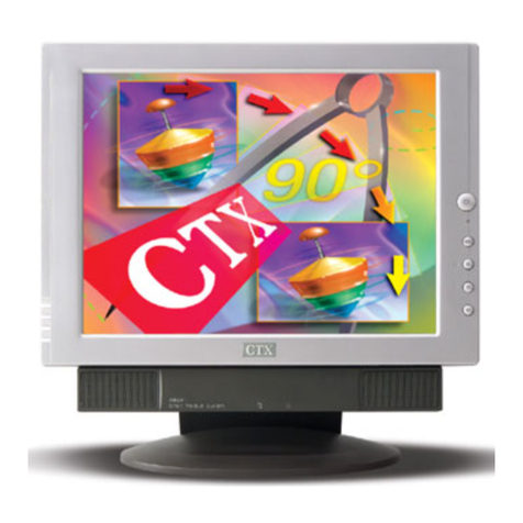
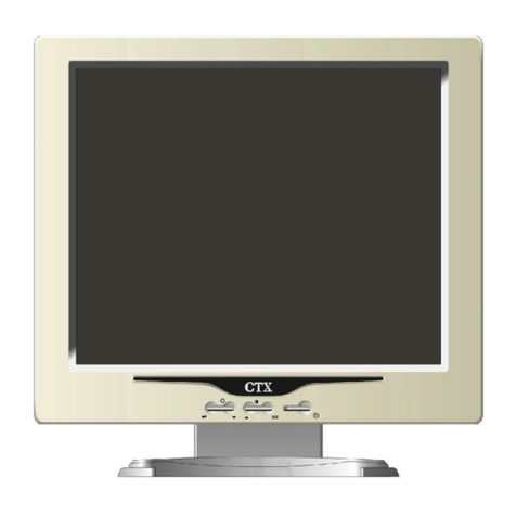
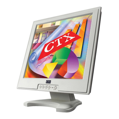
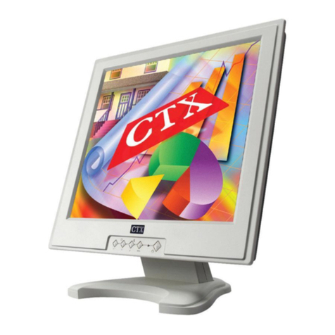
CTX 1565D User manual


CONTENTS
1.0
IMPORTANT
NOTICE
&
INTRODUCTION
000.0...
csc
ceceeseecseressneeseesncsecseeeessseeeseneeseatensees
1
2.0
GENERAL
MAINTENANCE
PROCEDURE
...............:cccsscceescceseensessersuceeseeeseeecssessesseeesses
2
3.0
FUNCTION
BLOCK
DIAGRAM
BLOCK
0...
cceeeccececscesecececeeseenseccessesscneesceeeecceeaseeeseteess
3
4.0
TIMING
MODE
(CTX
Presetting
Timing)
..............---eccsccseccccecessseevscssnssseaeeeeeeeeeseeesseeeeenens
4
5;
DADJUST
IMENT
csivessccevasteslaceics
Seade
cesta
sail
aiztsd
ep
seuritsogenisesssoeeseducuiSencasee
seeeceeatenenenteaeetentenees
6
6:0
TROUBLESHOOTING
\issssessiscccs
sc
ebedeesezneansdenticds
eieeeesddcseccdieccsteuscaseavesnossossasatedeanatecaaeaes
8
6.1
MAIN
TROUBLESHOOTING
ROUTINE
..........
cece
cece
ee
eecsceeeessereeeeceseeeeeeeseeseeeeenenes
8
6.2
POWER
SAVING
CIRCUIT
TROUBLESHOOTING
ROUTINE
..........:::::cecceeeeeereees
9
6.3
POWER
SUPPLY
CIRCUIT
TROUBLESHOOTING
ROUTINE.........:cssscsssesseeerenes
11
6.4
VIDEO
CIRCUIT
TROUBLESHOOTING
ROUTINE..........cscsssssceseeceereseesnersceesatsenes
13
6.5
DEFLECTION
CIRCUIT
TROUBLESHOOTING
ROUTINE.
...........::cseeessreeesereeenes
15
6.5.1
Horizontal
Deflection
Circuit
.............
ec
eceessenneneeecereaseeeeeeneseeeaeanaenereennaees
15
NO:
ROSEN
ccse5555
ssetsdaceets
avec
Oem
en
sae
te
ess
an
ees;
eee
eae
15
H-ASYNCHIONOUS.........eesecceeeeesceeceeeseeeenseescennaeeeesanseecseeessesesconecetensoreeerensenens
16
LITO
ANALY.
2
co
scch
eco
cias
ek
Fe
sacs
Fea
tan
si
vases
cca
becd
ogee
Sexscnceseacd
cuevasseatventestucetesvacdeeseedus
ase
17
Out
Of
Phase
.............scesssccelecccseseccsssterecsnssscescsnrsnsnegsrsaccesanaeesoea
nn
esscnossesenoeee
18
Width
Abnormal
...............ecccceceeseecesssseessscceesssncesessaaseeseerseeneessenaeseaverseeenenses
18
6.5.2
Vertical
Deflection
Circuit
..........
ce
ececeeeeseensnrseesersentenseeeessesseneceseeeerarenenes
19
NO
Vertical
SCAN
........
eee
cceececceseeeesserseeeeoessssscaceneseeesssseeceeeesecsesesnanseesensenes
19
Side
pir
GiStOtION
«2.0.0.2...
ee
eee
teeeeeceetensceceeeeeressesnseseeeneasenssaaneeseeeeceseneres
20
V-ASYNCHIONOUS...........seccccceeeessseesecceresesnesceensensccnecesecessseeeessnsnseesesesesenecentaens
21
Vertical
position
.....:.........eessssscssceesseeeseceeeeeeesseececesenessaanessesaceesonerrsresereesseres
21
Vertical
SIZ
2.cccc.ssciccdcccdogeaiectec
ck
cebe
csc
ndl
Shad
aaa
vbagedadao
bees
ssiesevtteastes
sea
en
eis
22
7.0
1C
CONFIGURATION
.................ccceceeceteccececececnereesearessccneeesasensussesesansaneanaereauseaseeeereseeeees
28
8.0
LAYOUT
FOR
MAIN
COMPONENTS
AND
ADJUSTED
..........ceccceececseseeeeeeeeeteneeneneeeneets
29
9.0
CIRCUIT
DIAGRAM.
ss
cscese
cudvastacenasscsvetoccdaclaicetitelanodwsadecedauateeseunstysucecoseadeegevieds
cacceeseoee
29
40.0
RECOMMENDED
SPARE
PARTS
LIST
...........ceccesecseceeeessnsneneereeesteesesncenseeesneseeensneeees
30
11.0
CRT
CONTRAST
LIST
uu...
ee
eeeeeceeeceeeseceensececeesssneecaeesenesaneesesercrsesrssecensseseneeeseneeerens
31

Copyright
©1995
by
Chuntex
Electronic
Co.,
Ltd.
The
CTX
TROUBLESHOOTING
GUIDE
is
published
by
Chuntex
Electronic
Co.,
Ltd.
All
rights
reserved.
No
part
of
this
manual
may
be
used,
copied,
reproduced,
or
transmitted
in
any
form
or
by
any
means
for
any
purpose
without
the
express
written
permission
of
the
publisher.
.
The
publisher
has
been
trying
its
best
to
make
this
publication
perfect,
and
in
this
manner
takes
no
responsi.
tity
for
the
use
of
any
of
the
materials
or
methods
described
in
this
manual,
or
for
the
products
thereof.
Neither
will
the
publisher
be
responsible
for
any
damages
caused
by
misuse
or
misquotation.
Information
in
this
manual
is
subject
to
change
by
the
publisher
without
any
notice
in
advance.
CTX
is
a
registered
trademark
of
Chuntex
Electronic
Co.,
Ltd.

1565D
1.0
IMPORTANT
NOTICE
&
INTRODUCTION
IMPORTANT
NOTICE
Please
read
before
attempting
service
1.
While
the
monitor
is
in
operation,
do
not
attempt
to
connect
or
disconnect
any
wires.
.
Make
sure
the
power
cord
is
disconnected
before
replacing
any
parts
in
the
monitor.
.
When
the
power
is
on,
do
not
attempt
to
short
any
portion
of
the
circuit.
This
shorting
may
cause
damage
to
the
transistors
in
the
monitor.
.
When
servicing
the
H.V.
area,
be
certain
that
the
C.R.T
anode
is
safely
discharged
before
removing
the
anode
cap.
.
Caution
must
exercised
when
servicing
this
monitor.
INTRODUCTION
Enhanced
repair
capabilities
This
troubleshooting
guide
is
edited
for
model
1565D
when
service
is
necessary.
there
are
four
primary
parts
included
in
this
troubleshooting
guide
which
offer
the
-easiest
way
to
locate
problem
points
and
repair
the
machine
to
the
best
possible
condition.
1.
The
Adjustment
section
offers
the
adjustable
method,
steps
and
all
data
of
the
factory's
initial
settings
which
can
make
the
machine
get
the
best
performance
at
that
time.
By
the
way,
before
adjusting,
the
machine
must
be
warmed
up
for
at
least
10
minutes
and
the
CRT
face
must
be
in
an
east
ward
direction.
.
The
Troubleshooting
section
has
four
main
parts
including:
power
supply,
power
saving,
CRT,
deflection
&
video
circuit.
Each
offers
fast
repair
routine
and
the
IC,
transistor
voltage
records
against
all
specified
signal
modes.
These
voltage
readings
are
measured
wth
a
HP
34401A
multimeter
with
input
impedance
10MQ
(0.1V~
1000V
range)
and
waveforms
shown
on
circuit
schematics
are
measured
by
a
Tektronix
TDS
520
digital
oscilloscope,
the
monitor
receives
VGA-480
full
white
square
pattern.
CTX
1.0
IMPORTANT
NOTICE
&
INTRODUCTION
.
The
CRT
contrast
list
offers
repairmen
/
technicians
the
contrast
data
when
CRT
replacement
is
necessary
from
a
different
type
of
CRT.
.
The
Spare
parts
list
offers
the
CTX
part
“number
(P/N)
which
is
used
frequently
by
repairmen
/
technicians.
For
details
please
refer
to
the
service
guide
or
service
manual.
If
there
is
any
engineering
change
regarding
this
model,
CTX
will
issue
the
updated
information
by
a
non-periodical
Technical
Bulletin.

2.0
GENERAL
MAINTENANCE
PROCEDURE
2.0
GENERAL
MAINTENANCE
PROCEDURE
START
CHECK
AND
RECORD
THE
.
FAILURE
MODE
OF
CUSTOMER
VISUAL
CHECK
THE
APPEARANCE
OF
CABINET/
CRT
CHECK
PICTURE
PERFORMANCE
NG
OK
REPLACEMENT
|
BURN
IN
24
HOURS
NG
RE-CHECK
PICTURE
PERFORMANCE
RECORD
1565D
REPLACEMENT
CTX
©

1565D
3.0
FUNCTION
BLOCK
DIAGRAM
BLOCK
3.0
FUNCTION
BLOCK
DIAGRAM
BLOCK
AC
UP
PIN
KEYSTONE
BAD
GAD
CTX
>
486V
>
+36V
POWER
>
425
SUPPLY
Db
+12V
>
+6V
POWER
SAVING
H
SYNC
.
MICRO
PROCESSOR
&
VSYNC
.
PINCUSHION
CORRECTION
Q503,504
Q512
V-SIZE
V-CENTER
EEPROM
IC501,IC502
HORIZONTAL
&
VERTICAL
PROCESSOR
1C201
(LA7851)
CS
CONTROL
Q704,Q705
Q706,C708
C710,C712
0c
TO
Dc
1€401,Q401
R
L401,D407
J
aS
VERTICAL
HORIZONTAL
HOR.O/P
HIGH
VOLTAGE
HOR-YORK
p
DRIVER
Q701,0702
P|
DEFECTION
H.V
O/P
{C801
Q702,T701
FBT(T702)
>
VERT.
YORK
H.V
REGULATOR
Q711,712
Q713,714
€705,Q708
VIDEO
PRE-AMP
1C601
CRT
(M51387)

H
TOTAL
4.0
TIMING
MODE
(CTX
Presetting
Timing)
1565D
4.0
TIMING
MODE
(CTX
Presetting
Timing
+)
a
[roams
[awe
[same
|
sane
|
ome
|
ome
|
ome
[Tn
[me
[me
[ew
|
eome
|
mune
|
me
ee
[foe
|e
|
»
|» |»
|
MODE
acute]
vam
|
oso
|
im
|
om
|
vm
|
vam
|
fewcennea
|
we
[we
|
w
| |
|
=
[wr
[Poe
[rn
[rom
[roe
[re
mn
[roe]
mt
[rm
|
mi
[rm
ma
FRAME
BORDER-H
|
FRAME
ae
a
BORDER-V
conn
|
elo
el
[eel
|
Biel
|
ee
fe
a
we
|
3.
128
420
36
H
SYNC
WIDTH
96
3.81
us}
96
3.81
us
3.81
us
3.2
us
240us!|
1
2.092
us
HSYNC
POLARITY
a7
+
+
Es
cs
el
ie
fc
Ma
a
A
ee
vemowora
|
2
jooeme|
2
[raceme
4
[arosm)
+
larcom|
©
[oaasme|
@
[ataam
|
-
|
+
|
+
f{-
-
|
eae
ee
SERRATION
?
COMP
SYNC
POLARITY
4
CTX

1565D
4.0
TIMING
MODE
(CTX
Presetting
Timing)
*
V1024-70
=
[Te
|
~
|
«|
[ee
[ee fem
|
[seconnse
|
we
fe
PIXEL
|
msfus
|
PIXEL.
PIXEL
-
FRAME
BORDER-H
FRAME
BORDER-V
a
renee
i
es
ee
H
SYNC
POLARITY
7
+
+
a
a
8
Ni
I
:
I
8
I
:
ms/us
a
ale
¢
V
TOTAL
veneer
a
V
SYNC
POLARITY
+
+
+
COMP
SYNC
POLARITY
CTX
5

5.0
ADJUSTMENT
5.0
ADJUSTMENT
5.1
1565D
ADJUSTMENT
Brightness
reduce
voltage
adjustment:
VR101,VR102
/-
VGA-480
1.
Use
VGA-480
timing
for
input
signal.
2.
Attach
the
multimeter
(with
a
DC
voltage
range
of
200V)
adjust
VR101
to
get
85.5V
£0.5V
at
TP1.
3.
Adjust
VR102
to
get
12V+0.05V
at
TP2.
Hi-volitage
adjustment:
VR702
/
VGA-480
a.
Turn
the
power
switch
off
before
attaching
multimeter
with
a
high
voltage
probe
by
a
factor
1000:1
between
CRT
anode
and
GND.
b.
Adjust
VR702
to
make
sure
the
measurement
readings
are
25.0V
+
0.2V
(ie
CRT
anode
voltage
is
25.0KV+0.2KV).
Horizontal
hold
adjustment:
VR201,VR202
a.
Connect
TP4
to
GND
and
adjust
VR202
to
get
picture
stand
or
scroll
toward
left
or
right
slowy
when
input
is
8514A
timing
signal.
b.
Change
input
timing
to
VESA1024
and
adjust
VR201
to
get
picture
stand.
.
H-PHASE
adjustment:
EXT
SW
/
ALL
MODE
Adjust
EXTERNAL
H-PHASE
SW
to
shift
.
picture
to
the
center
of
screen,
every
mode.
V-line
adjustment:VR801
/
VESA1024
First
adjust
V-CENTER
EXTERNAL
VR
to
make
picture
to
the
V-center
of
the
screen,
and
then
adjust
VR801
to
correct
the
V-linearity
of
crossh-hatch
pattem.
|
|
|
|
|
|
y
1565D
H-WIDTH
adjustment:
VR401
/
VI1024
a.
Tum
EXTERNAL
H-WIDTH
VR
to
min.
position.
b.
Adjust
VR401
to
get
the
picture's
width
is
260+5mm.
V-SIZE
adjustment:
EXT
SW
/
ALL
MODE
Adjust
EXT
V-SIZE
SW
to
get
vertical
size
of
each
mode
is
202+5mm.
PARALLELOGRAM
adustment:
VR204
/
ALL
MODE
Adjust
VR204
to
get
a
picture
that
right
edge
parallel
with
left
edge
of
each
mode;
which
the
spec.
is
+2mm.
’
FOCUS
adjustment:
FOCUS
VR
/
VGA-480
Adjust
FOCUS
VR
on
the
FBT
to
attain
a
balanced
focus
for
all
zones
on
the
screen.
White
balance
adjustment:
a.
Pre
adj.
&
brightness
settings
(Before
adjusting,
CRT
must
be
degaussed.)
(1)
Please
set
the
VR601,
602,
603,
604,
605,
606
on
mechanical
center,
and
_
the
Brightness
VR
to
the
click
point,
the
Contrast
VR
to
Max..
(2)
Operating
on
VGA-480
mosaic
pattern
and
adjust
the
SCREEN
VR
to
set
the
raster
luminance
between
1
~
2FL,
then
adjust
VR604,605,606
(BIAS
VR)
to
make
the
rasters
C.I.E.
coordinates
value
as
x=0.281
+
0.01,
y=0.311
+=
0.01
were
measured
by
color
analyzer.
(3)
Change
timing
to
VGA-400
color
bar
pattem,
correct
SCREEN
VR
whitch
on
the
FBT
to
make
raster
brightness
disapper
and
the
"1"
row
of
color
bar
pattem
(as
below
figure)
visible
obscurely.
2
—visible
1
—visible
obscurely
CTX

1565D
b.
White
balance
fine
regulation:
(1)
Receive
VGA-480
timing,
full
white
square
pattem.
(2)
Adjust
Brightness
VR.
to
MIN.,
Contrast
VR.
to
MAX..
(3)
Adjust
VR601,602,603
to
make
picture
C.1.E.
coordinates
value
as
x=0.281
+
0.01,
y=0.311
+£0.01,
were
measured
by
color
Analyzer.
(4)
Change
the
BRIT.
VR
to
the
click
point
and
adjust
the
CONT.
VR
to
make
the
luminance
of
picture
between
1
~
2FL,
then
adjust
VRE04,
605,
606
(BIAS
VR)
to
get
X=0.281
+
0.005,
Y=0.311
+
0.005,
were
measured
by
color
Analyzer.
(5)
If
the
white
balance
is
not
met,
repeat
step
(2)
~(4).
Please
set
Brightness
VR
to
click
point
and
Contrast
VR
to
Max.,
and
check
item
(3)
of
Per
adj
&
brightness
settings,
then
receive
VGA-480
mosaic
pattem
and
check
the
luminance
of
Mosaic
pattern
is
between
50~
60FL.
if
above
check
item
isn't
meet,
please
modify
VR601
~
VR605
and
retum
to
white
balance
fine
regulation
section.
ADJUSTMENT
FOR
CONVERGENCE
(1)
Use
a
magenta
crosshatch
on
the
display.
(2)
Adjust
the
focus
for
the
best
overall
focus
on
the
screen.
(3)Aiso
adjust
the
brightness
to
the
desired
condition.
(4)
Vertical
red
and
blue
lines
are
converged
by
varying
the
angie
between
the
two
tabs
of
the
4
pole
magnets
on
the
PCM
assembly.
(See
diagram
below)
(5)
Horizontal
red
and
blue
lines
are
converged
by
moving
the
two
tabs
at
the
same
time
keeping
the
angle
between
them
constant.
(6)
Use
a
white
crosshatch
pattem
on
the
display.
(7)
Vertical
green
and
magenta
lines
are
converged
by
varying
the
angle
between
the
two
tabs
of
the
6-pole
magnets.
CTX
5.0
ADJUSTMENT
(8)
Horizontal
green
and
magenta
lines
are
converged
by
moving
the
two
tabs
at
the
same
time.
keeping
the
angle
between
them
constant.
DEFLECTION
YOKE
Xe
6-POLE
CONVERGENCE
MAGNETS
4POU
E
CONVERGENCE
MAGNETS
PURITY
MAGNETS
PCM:PURITY
CONVERGENCE
MAGNET
Note:
Please
don't
adjust
the
purity
magnets
when
service
occurs.

6.0
TROUBLESHOOTING
6.0
TROUBLESHOOTING
1565D
6.1
MAIN
TROUBLESHOOTING
ROUTINE
START
CHECK
POWER
INDICATOR
LED
LED
COLOR
7
DOES
IMAGE
APPEAR
CHECK
COLOR
PERFORMANCE
CHECK
GEOMETRIC
PERFORMANCE
NG
AMBER
ING
POWER
SUPPLY
CKT.
TROUBLESHOOTING
ROUTINE
POWER
SAVING
CKT.
TROUBLESHOOTING
ROUTINE
POWER
SUPPLY
CKT.
TROUBLESHOOTING
ROUTINE
&
ADJUSTMENT
CHECK
85.5V,36V,25v,
12V,5V,6.2V
DOES
RASTER
APPEAR
?
DEFLECTION
CKT.
(ADJUST
SCREEN
VR
ON
TROUBLESHOOTING
FBT)
ROUTINE
&
ADJUSTMNET
VIDEO
CKT.
TROUBLESHOOTING
ROUTINE
DEFLECTION
CKT.
TROUBLESHOOTING
ROUTINE
CTX

1565D
6.0
TROUBLESHOOTING
6.2
POWER
SAVING
CIRCUIT
TROUBLESHOOTING
ROUTINE
START
IS
THE
POWER
SAVING
FUNCTION
NORMAL
?
IS
THE
INPUT
SIGNAL
NORMAL
?
CHECK
PIN
34,35,33
VOLTAGE
OF
IC501
CHECK
BASE
VOTAGE
OF
Q108,
Q111
CHECK
BASE
VOLTAGE
OF
Q106,
Q110
CHECK
THE
SIGNAL
CABLE
CHECK
IC501
AND
ITS.
PERIPHERAL
PARTS
CHECK
THE
Q108,Q111
AND
THEIR
PERIPHERAL
PARTS
CHECK
THE
Q106,
Q110
AND
THEIR
PERIPHERAL
PARTS
CTX

6.0
TROUBLESHOOTING
1565D
VOLTAGE
MEASURED
RECORD
TEST
CONDITIONS:
TIMING
—
:
VGA-480
PATTERN:
CROSS
HATCH
Unit:
Voit
Pera,
(aa
a
a
a
ee
ee
ee
STATUS
fuorunc
|
eno
fame
|
ome
|
mee
|
are
|
moo
[em
|
an
|
eer
Tree
ase
[ae
fusreno|
eno
|
ts7
|
om
|
aox0
|
200
|
2020
|
Por
[ew
|
ter
|
ow
|
arse
|
200
|
mae
|
see
|
wee
|
28
Q110
(2SB772)
CTX

1565D
6.0
TROUBLESHOOTING
6.3
POWER
SUPPLY
CIRCUIT
TROUBLESHOOTING
ROUTINE
START
CHECK
AC
COMPONENTS
CHEC
VOLTS
O
NG
5
stash
ae
.
NTC101,L103,C103,C102,C101,
L102,SW101,
F101
OK
01
CHECK
GATE
VOLTAGE
OF
CHECK
VOLTAGE
OF
C101
CHECK
@101,Q103,D1
Q104
D102,D104,D105
CHECK
Q104,D107,R120
R121,R123,R126
CHECK
THE
AC
OUTPUT
AT
|
NG
2ND
WINDING
OF
T101
CHECK
Q104,T101
CHECK
D108
~112,L104,L106,
L401,C119~125,ZD106
CTX
11

6.0
TROUBLESHOOTING
1565D
VOLTAGE
MEASURED
RECORD
TEST
CONDITIONS:
TIMING
:
VGA-480
|
PATTERN:
CROSS
HATCH
.
Unit:
Volt
12
CTX:

1565D
6.0
TROUBLESHOOTING
6.4
VIDEO
CIRCUIT
TROUBLESHOOTING
ROUTINE
START
CHECK
COLLECTOR
OK
CHECK
VOLTAGE
OF
C616~C618,R643~R645,
Q604,Q605,Q606
CRT
SOCKET
&
CRT
NG
CHECK
BASE
VOLTAGE
OF
Q601,Q602,Q603
NG
CHECK
PIN
21,25,29
~R6I6
VOLTAGE
OF
IC601
CHECK
REI
iet
NG
CHECK
PIN
15
CLAMPING
OK
VOLTAGE
OF
IC601
CHECK
P602,R648,IC601
NG
OK
CHECK
P601
AND
SIGNAL
CABLE
OR
NO
SIGNAL
INPUT
CHECK
SIGNAL
INPUT
AT
PIN
3,7,14
OF
iC601
CHECK
C634,C627,L604,IC601
CHECK
IC601,P602
*
The
Troubleshooting
Routine
is
match
P/N
11S33-019A
CRT
board.
CTX
13

6.0
TROUBLESHOOTING
_
1565D
The
following
voltage
records
was
measured
with
full
white
square
pattern.
Transistor
&
Integration
circuit
Unit:
Volt
Q601
(PH2369)
Q602
(PH2369)
Q603
(PH2369)
veaseo]
aoe
|
oar
|
aor
|
om
|
ane
|
Q604
=
Q605
ad
Q606
ase
ea-ao|
soe
|
we
[oe
|
oa
|
we
|
ea
|
oor
IC601
(M51387)
et
eae
Ce
ee
veaaeo
|
no
|
120
|
270
|
sox
|
nc
|
zo
|
27
|
496
|
1C601
(M51387)
14
CTX

1565D
6.5
DEFLECTION
CIRCUIT
TROUBLESHOOTING
ROUTINE
6.5.1
Horizontal
Deflection
Circuit
CHECK
Q701,D702,FBT
CHECK
Q701
,Q702,T701,
Q206,Q207,R703,R701,
C731
CHECK
1C201
OR
IT'S
PERIPHERAL
SUCH
AS
R230,R231,C204,C206
C207,C219,C221
OK
No
Raster
START
6.0
TROUBLESHOOTING
FOR
DC
TO
DC
CONTROL
LOOP
CHECK
PIN
2
VOLTAGEF
OF
FBT(DISCONNECT
COLLECTOR
OF
Q401
WHEN
MEASURED
CHECK
CATHOD
VOLTAGE
OF
D407
OK
IS
THE
OUTPUT
VOLTAGE
OF
D109
CHECK
BASE
|
36VDC
VOLTAGE
OF
Q701
NG
|
POWER
SUPPLY
TROUBLESHOOTING
ROUTING
CHECK
PIN
12
VOLTAGE
OF
IC201
CHECK
PIN
1
H-SYNC.
INPUT
OF
[C201
NG
CHECK
Q511,Q505
R564,C201
CHECK
PIN
38
OF
IC501
CHECK
ICSO1
OR
ITS
PERIPHERAL
PARTS
CHECK
PIN
40
OF
1C501
CHECK
P503,P602,P601
AND
SIGNAL
CABLE
CHECK
D407
&
RELATED
TRACE
TO
FBT
|
CHECK
I1C401,Q401
&
THEIR
PERIPHRAL
|
COMPONENTS
CTX
15

6.0
TROUBLESHOOTING
,
1565D
H-Asynchronous
START
SHORT
TP4
TO
GROUND
,
THEN
ADJUST
8514A
(VR202);
V1024(VR201)
OF
H-HOLD
OK
CHECK
PIN
1
OF
1C201
SIGNAL
CHECK
1C501
,P503,
SIGNAL
CABLE
P601
CHECK
H-FIV
VOLTAGE
AT
PIN
24
OF
IC501
CHECK
AFC
VOLTAGE
|
OK
AT
PIN
4,7
OF
1C201
CHECK
1C201
AND
ITS
PERIPERAL
PARTS
CHECK
1C201,D501,
Q515,Q203
CHECK
IC501
AND
ITS
PERIPHERAL
COMPONENTS
CHECK
R212,R213
C204
16
CTX

1565D
6.0
TROUBLESHOOTING
Linearity
START
(USE
CROSS-HATCH
PATTERN)
(LINEAR
COIL)
YES
DOES
PICTURE
LEFT
SQUARE
CHECK
L701,0703
MORE
BIG
THAN
RIGHT
NO
Bee
DOR
ONTAL
VOLTAGE
OF
IC501
YES
CHECK
GATE
VOLTAGE
OF
CHECK
Q508,Q509,
CHECK
IC501
AND
Q704,Q705,Q706
ARE
"L'"L","L"
WITH
HORIZONTAL
ie
Q510
AND
THEIR
IT'S
PERIPHERAL
FREQ.
64K
PERIPHERAL
PARTS
COMPONENTS
CHECK
Q704,Q705,Q706
&
ITS
PERIPHERAL
COMPONENT:
SUCH
AS
C708,C710,C712
REMARK:
x
"L"
means
the
voltage
between
gate
and
source
is<0.7V
which
can't
tum
on
the
MOSFET.
+
*&
"H"
means
the
voltage
between
gate
and
source
is=0.7V
which
can
turn
on
the
MOSFET.
CTX
.
17
Table of contents
Other CTX Monitor manuals

