Cuisinart CPT-200 User manual
1
• Not for permanent
installation.
• For outdoor use only
• Use caution with all electric
appliances, tools, extension
cords and lights on and
around table.
• Surface can become
hot in direct sun or high
temperatures.
• Maximum top weight load of
50 LBS
• Maximum shelf weight load
of 30 LBS
• Use only on level surfaces.
• Do not allow children to
climb the product.
WARNING
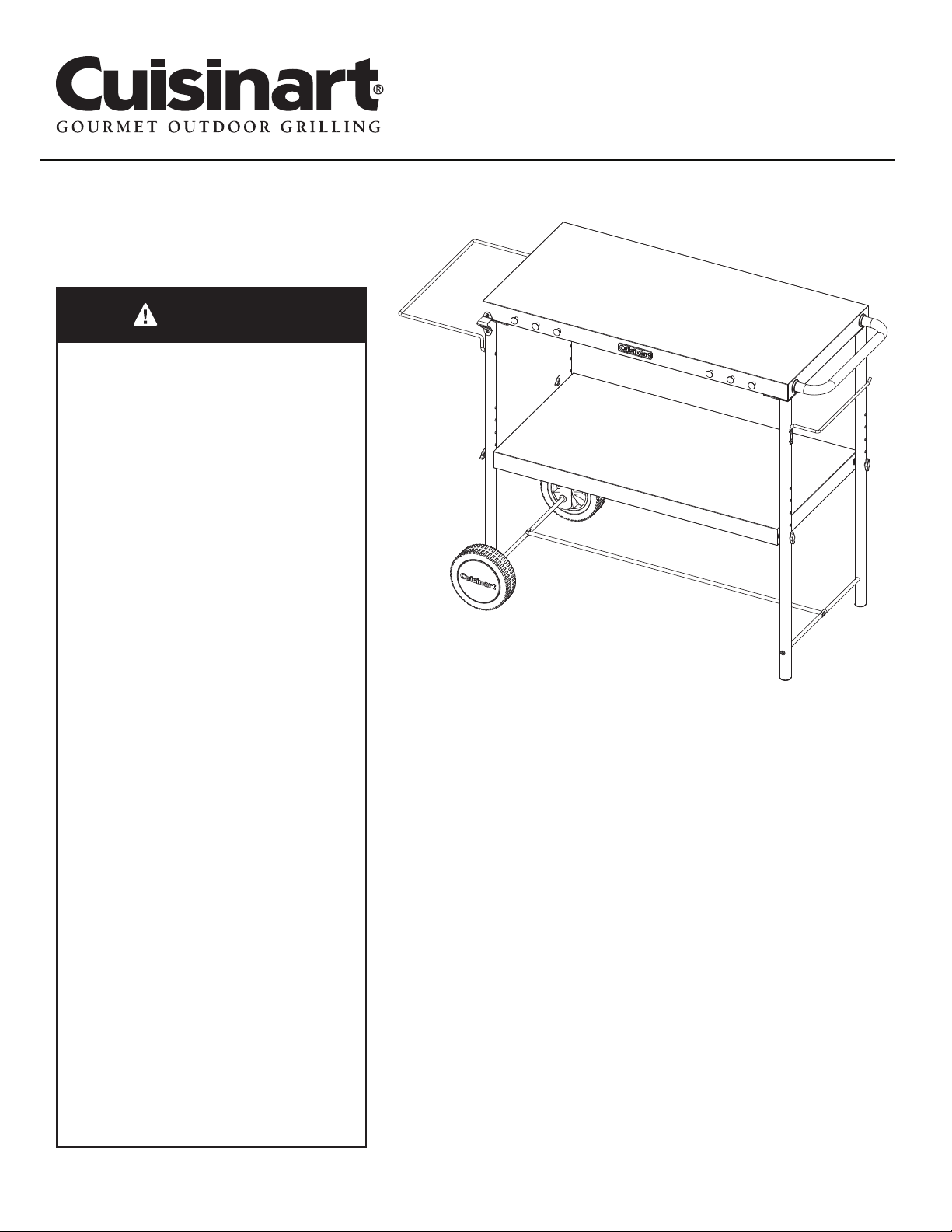
Model NO: CPT-200
Outdoor Prep Cart
DO NOT RETURN YOUR PREP CART TO THE STORE
Before visiting your local retailer, call our customer
service department at 1-866-994-6390 from 9:00 am
to 5:00 pm Eastern Time, Monday through Friday.
Customer Service Hotline
1-866-994-6390
CALIFORNIA PROPOSITION 65
WARNING:
• WARNING: This product may
expose you to chemicals
including Nickel and
Chromium which are known
to the State of California
to cause cancer. Stainless-
Steel products present
no health hazard in their
natural state during use,
storage, and transportation,
but may present a hazard
when in dust form. For more
information, go to www.
P65Warnings.ca.gov

Table of Contents
Table of Contents 2
Package Contents List 3
Assembly Instructions 4
Care and Maintenance 12
Exploded View 12
Parts List 13
Warranty & Replacement Parts Back Cover
Questions? Back Cover
2

3
WHAT’S IN THE BOX
COMPONENTS
--------------------------------------------------------------------------------------
HARDWARE
--------------------------------------------------------------------------------------
1
Left rear
leg
Right front
leg
Right rear
leg
Support
beam (B)
Support
beam (A)
Storage
shelf
Hand
screws
Wheel axel
Left front
leg
1pc
1pc
1pc
1pc
1pc
1pc
2
3
4
5
6
1pc7
4pc8
1pc9
Truss head screw
5/32 - 32x25/64
Tool hook screw
3.5x12
Washer
Tool hook
washer
Wheel nut
Truss head screw
1/4 - 20x1/2 18pc
2pc
A
B
6pcC
Handle
assembly
Counter top
assembly
Tool hooks
Bottle
opener
Trash bag
holder
Paper towel
holder
Wheels
Wheel cap
2pc
1pc
6pc
1pc
1pc
10
11
12
13
14
1pc15
1pc16
2pc17
PART DESCRIPTION QTY
PART DESCRIPTION QTY
6pc
6pc
D
E
2pcF
PART DESCRIPTION QTY
PART DESCRIPTION QTY
4
ASSEMBLY INSTRUCTIONS
Before beginning assembly, installation or operation of product, make sure all parts are present. Compare parts
with package contents list and exploded view (p.12). If any part is missing or damaged, do not attempt to assem-
ble, install or operate the product. Contact customer service for replacement parts.
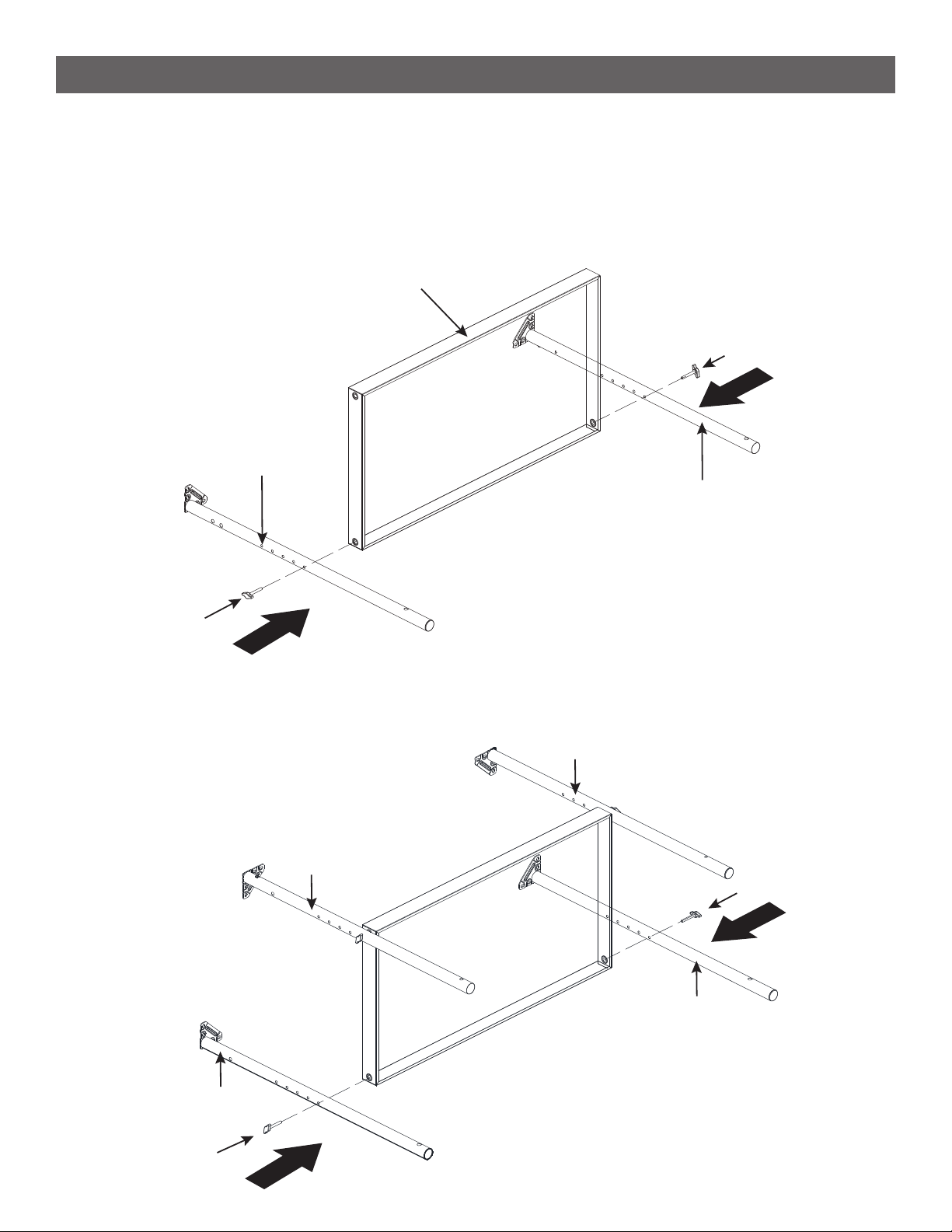
STEP 2
--------------------------------------------------------------------------------------
• Connect the left rear leg (2) and the right rear leg (4) to the storage shelf (7) using 2 hand screws (8). Do not
fully tighten hand screws.
STEP 1
--------------------------------------------------------------------------------------
• Connect the right front leg (3) and the left front leg (1) to the storage shelf (7) using 2 hand screws (8). Do
not fully tighten hand screws. 7
3
1
8
8
3
4
2
1
8
8
5
ASSEMBLY INSTRUCTIONS
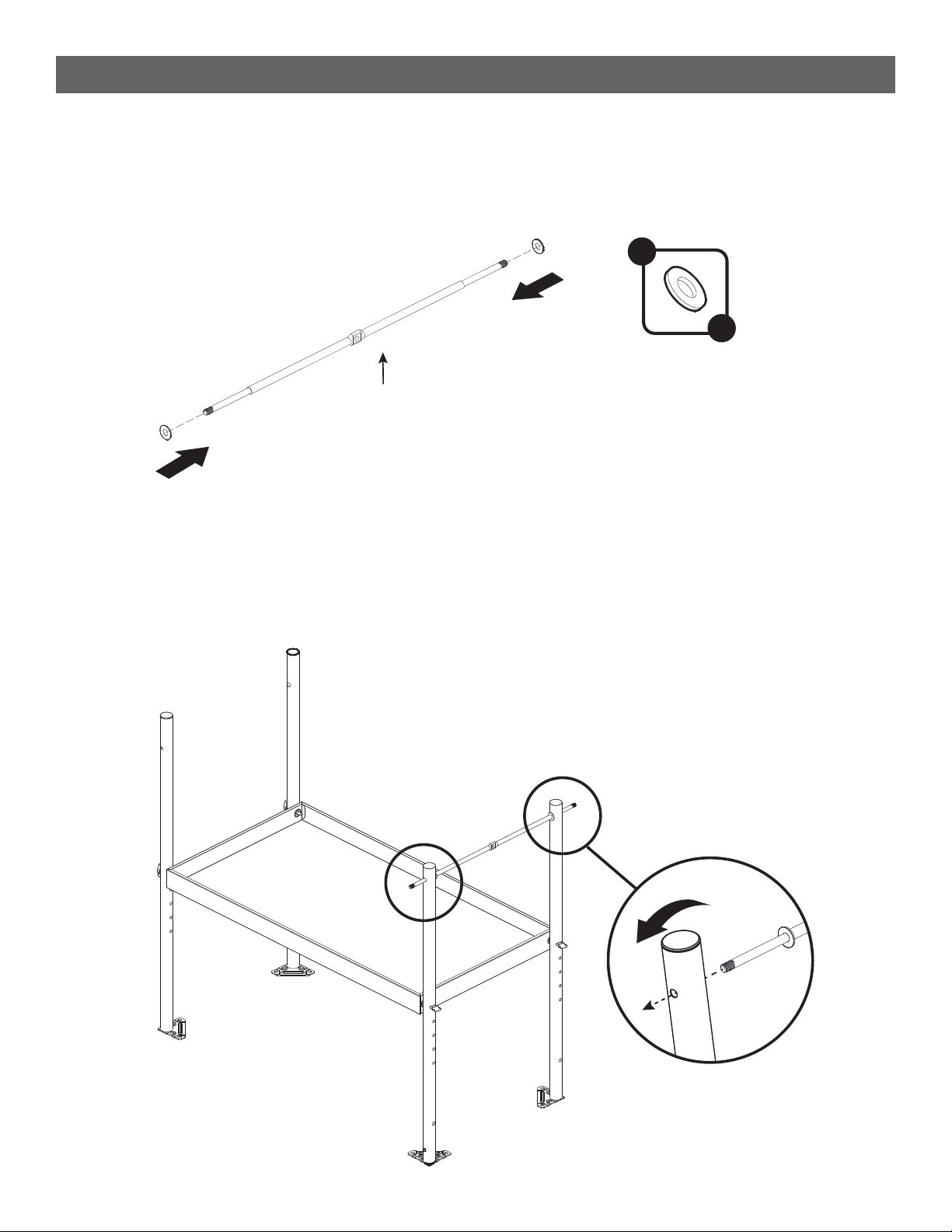
STEP 3
--------------------------------------------------------------------------------------
• Add 1 Dwasher to either end of the wheel axle
(5).
STEP 4
--------------------------------------------------------------------------------------
•Flip the frame over as shown below.
•Insert the wheel axle (5) in to the bottom holes of the left legs. Tilt the legs as necessary to t the axle
between.
5
D
x 2
6
ASSEMBLY INSTRUCTIONS
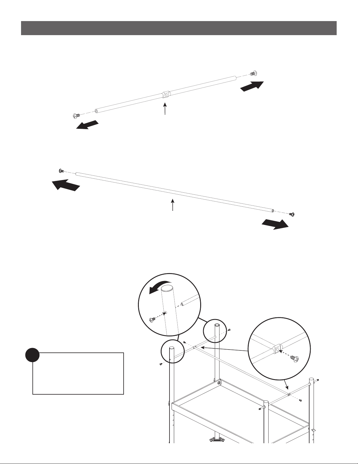
STEP 5
--------------------------------------------------------------------------------------
•Remove 1 screw from either end of the frame support beam B (6).
STEP 6
--------------------------------------------------------------------------------------
•Remove 1 screw from either end of the frame support beam A (9).
6
9
STEP 7
--------------------------------------------------------------------------------------
•Insert the frame support beam B in to the bottom holes of the right legs and replace the screws.
•Then position the frame support beam A between the frame support beam B and the wheel axle and
replace the screws.
Note: Do not tighten
screws in this step fully
until frame support beam A
is in place.
!

F
x 2
10
10
D
x 4
7
ASSEMBLY INSTRUCTIONS
STEP 8
--------------------------------------------------------------------------------------
•Add one D washer to either end of the wheel axle then place the wheels (10) on. Add an additional D
washer to the outside of each wheel and secure using 1 F nut on either side. Tighten with a wrench.
STEP 9
--------------------------------------------------------------------------------------
•Add the wheel caps (17) to the wheels by lining up the pegs on the wheel caps with the holes on the
wheels. Press in rmly to attach.
17
17

8
ASSEMBLY INSTRUCTIONS
STEP 10
--------------------------------------------------------------------------------------
• Remove 1 screw from either end of the handle assembly (11).
STEP 11
--------------------------------------------------------------------------------------
• Attach the handle assembly to the right side of the counter top assembly (12) using the screws that were
previously removed.
11
12

A
x16
9
ASSEMBLY INSTRUCTIONS
STEP 12
--------------------------------------------------------------------------------------
• Attach the tool hooks (13) using 6 C screws and 6 E washers as shown below.
STEP 13
--------------------------------------------------------------------------------------
• Lift the frame on to the counter top assembly and line up the holes on the legs with the holes on the
counter top assembly as shown below. Use 4 A screws on each leg to secure.
C
x 6
E
x 6
Note: Make sure left front
leg is in the correct position
during this step.
!

10
ASSEMBLY INSTRUCTIONS
OPERATING THE GRILL
STEP 14
--------------------------------------------------------------------------------------
• Attach the bottle opener (14) to the left front leg using 2 B screws.
STEP 15
--------------------------------------------------------------------------------------
• Remove 2 screws from the trash bag holder (15)
B
x 2
14
15
Table of contents


