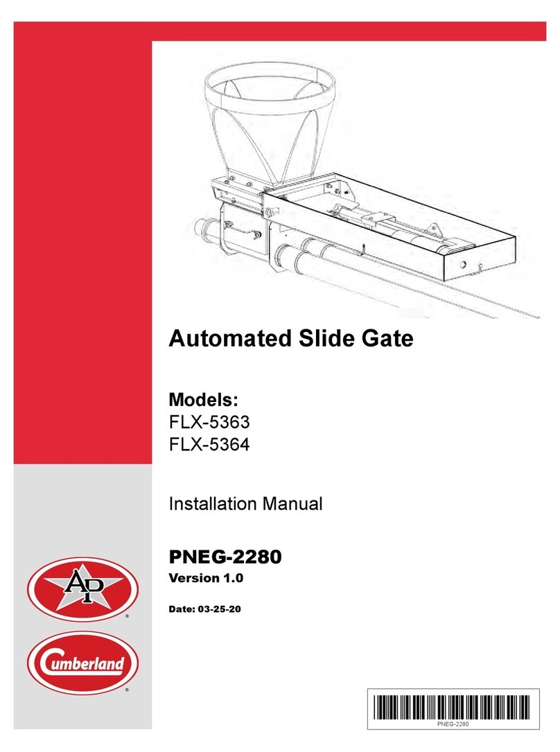
Cumberland FLX-5363 User manual

Automated Slide Gate
Models:
FLX-5363
FLX-5364
Operation Manual
PNEG-2320
Version 1.0
Date: 10-27-20
PNEG-2320

All information, illustrations, photos, and specifications in this manual are based on the latest
information available at the time of publication. The right is reserved to make changes at any
time without notice.
2PNEG-2320 Automated Slide Gate Operation

Contents
Chapter 1 Safety Precautions ....................................................................................................................5
Safety Guidelines........................................................................................................................5
Cautionary Symbol Definitions......................................................................................................6
Safety Cautions...........................................................................................................................7
Safety Sign-off Sheet.................................................................................................................10
Chapter 2 General Specifications and Operation..................................................................................... 11
General Overview ..................................................................................................................... 11
Specifications ........................................................................................................................... 11
User Interface ...........................................................................................................................12
Chapter 3 Configuring Settings for each Slide Gate ................................................................................13
Adjustable Parameters ..............................................................................................................13
Disabling an Actuator Slide ........................................................................................................14
Enabling an Actuator Slide.........................................................................................................14
Setting the Manual Operation.....................................................................................................15
Setting the Auto Operation .........................................................................................................15
Setting the Open Position ..........................................................................................................16
Calibration ................................................................................................................................16
Setting the Sensitivity ................................................................................................................17
Setting the Node ID ...................................................................................................................17
Clearing an Alarm .....................................................................................................................18
Chapter 4 General Movement/Operation..................................................................................................19
Chapter 5 Manual Mode Operation ..........................................................................................................21
Chapter 6 Slide Gate Operation using the Site Controller (FLX-5419) ......................................................23
Chapter 7 Troubleshooting......................................................................................................................25
Clearing an Obstruction .............................................................................................................25
Alarms......................................................................................................................................26
Limited Warranty - Protein Products .......................................................................................27
PNEG-2320 Automated Slide Gate Operation 3

NOTES
4PNEG-2320 Automated Slide Gate Operation

1Safety Precautions
Topics Covered in this Chapter
▪ Safety Guidelines
▪ Cautionary Symbol Definitions
▪ Safety Cautions
▪ Safety Sign-off Sheet
Safety Guidelines
Safety guidelines are general-to-specific safety rules that must be followed at all times. This manual is
written to help you understand safe operating procedures and problems that can be encountered by the
operator and other personnel when using this equipment. Read and save these instructions.
As owner or operator, you are responsible for understanding the requirements, hazards, and precautions
that exist and to inform others as required. Unqualified persons must stay out of the work area at all
times.
Alterations must not be made to the equipment. Alterations can produce dangerous situations resulting in
SERIOUS INJURY or DEATH.
This equipment must be installed in accordance with the current installation codes and applicable regula-
tions, which must be carefully followed in all cases. Authorities having jurisdiction must be consulted
before installations are made.
When necessary, you must consider the installation location relative to electrical, fuel and water utilities.
Personnel operating or working around equipment must read this manual. This manual must be delivered
with equipment to its owner. Failure to read this manual and its safety instructions is a misuse of the
equipment.
ST-0001–4
PNEG-2320 Automated Slide Gate Operation 5

Chapter 1: Safety Precautions
Cautionary Symbol Definitions
Cautionary symbols appear in this manual and on product decals. The symbols alert the user of potential
safety hazards, prohibited activities and mandatory actions. To help you recognize this information, we
use the symbols that are defined below.
Table 1-1 Description of the different cautionary symbols
Symbol Description
This symbol indicates an imminently hazardous situation which, if
not avoided, will result in serious injury or death.
This symbol indicates a potentially hazardous situation which, if not
avoided, can result in serious injury or death.
This symbol indicates a potentially hazardous situation which, if not
avoided, can result in minor or moderate injury.
This symbol is used to address practices not related to personal
injury.
This symbol indicates a general hazard.
This symbol indicates a prohibited activity.
This symbol indicates a mandatory action.
ST-0005–2
6PNEG-2320 Automated Slide Gate Operation

Chapter 1: Safety Precautions
Safety Cautions
Use Personal Protective Equipment
• Use appropriate personal protective equipment:
Eye
Protection
Respiratory
Protection
Foot
Protection
Hearing
Protection
Head
Protection
Fall
Protection
Hand
Protection
• Wear clothing appropriate to the job.
• Remove all jewelry.
• Tie long hair up and back.
ST-0004–1
Follow Safety Instructions
• Carefully read all safety messages in this manual and safety
signs on your machine. Keep signs in good condition.
Replace missing or damaged safety signs. Be sure new
equipment components and repair parts include the current
safety signs. Replacement safety signs are available from
the manufacturer.
• Learn how to operate the machine and how to use controls
properly. Do not let anyone operate without instruction.
• If you do not understand any part of this manual or need
assistance, contact your dealer.
ST-0002–1
PNEG-2320 Automated Slide Gate Operation 7

Chapter 1: Safety Precautions
Maintain Equipment and Work Area
• Understand service procedures before doing work. Keep
area clean and dry.
• Never service equipment while it is operating. Keep hands,
feet, and clothing away from moving parts.
• Keep your equipment in proper working condition. Replace
worn or broken parts immediately.
ST-0003–1
Lifting Hazard
• Single person lift can cause injury.
• Use a mechanical lifting device to lift or move the equipment
during installation.
ST-0021–2
Install and Operate Electrical Equipment Properly
• Electrical controls must be installed by a qualified electrician
and must meet the standards set by applicable local codes
(National Electrical Code for the US, Canadian Electric
Code, or EN60204 along with applicable European Direc-
tives for Europe).
• Lock-out power source before making adjustments, cleaning,
or maintaining equipment.
• Make sure all equipment is properly grounded.
ST-0027–4
Sharp Edge Hazard
• This product has sharp edges, which can cause serious
injury.
• To avoid injury, handle sharp edges with caution and always
use proper protective clothing and equipment.
ST-0036–2
8PNEG-2320 Automated Slide Gate Operation

Chapter 1: Safety Precautions
Rotating Auger Hazard
• Keep clear of rotating augers and
moving parts.
• Do not remove or modify guards or
covers.
• Lock-out power source before making
adjustments, cleaning, or maintaining
equipment.
• Failure to follow these precautions will
result in serious injury or death.
ST-0037–1
Stay Clear of Slide Gate
• Keep hands away from slide gate opening. Slide gates can
crush and dismember. Motor can start at any time.
• Lock-out power source before making adjustments, cleaning,
or maintaining equipment.
ST-0049–1
PNEG-2320 Automated Slide Gate Operation 9

Chapter 1: Safety Precautions
Safety Sign-off Sheet
Below is a sign-off sheet that can be used to verify that all personnel have read and understood the safety
instructions. This sign-off sheet is provided for your convenience and personal record keeping.
Date Employee Name Supervisor Name
ST-0007
10 PNEG-2320 Automated Slide Gate Operation

2General Specifications and
Operation
Topics Covered in this Chapter
▪ General Overview
▪ Specifications
▪ User Interface
General Overview
1. At start-up the unit will move the slide gate to the home position (the fully closed position) to
establish a known position.
2. The display will read “Slide 1:nn.n%” or “Slide 2:nn.n%”, depending on which slides are enabled.
If no slides are enabled, it will read “No slides”.
3. Each local slide gate controller (FLX-5416) can be configured with a maximum of two slide gates.
Each slide gate can be enabled or disabled. The controller is generally mounted to a bin leg. Each
controller can be given a node ID number to identify the bin where it is located.
4. Each slide gate site controller (FLX-5419) can control up to eight local slide gate controllers
(FLX-5416) with up to sixteen slide gates. The site controller (FLX-5419) allows you to remotely
operate the slide gates and set some parameters. It does not let you operate the slide gates in
manual mode.
5. The length of travel of the slide gate is a fixed length for all installations. The closed position is
determined by a physical limit switch. The limit switch is always sending a signal to the controller
indicating whether the switch is active or not active. At the start-up, the controller will attempt to
close the slide until the limit switch is tripped, thus setting the home/closed position. The full open
position will be a fixed length from the closed position.
Specifications
1. The local slide gate controller (FLX-5416) runs on 120V AC and each actuator has a FLA of 2.5
Amps. Each local controller (FLX-5416) has a maximum draw of 5 Amps.
2. The slide gate site controller (FLX-5419) runs on 24V DC and has a draw of 50 mA.
PNEG-2320 Automated Slide Gate Operation 11

Chapter 2: General Specifications and Operation
User Interface
Figure 2-1 User interface
Table 2-1 Controller display and button details
Ref
#
Display/
Buttons Description
1Display Displays current status information and parameter settings.
2Menu Use to advance through the configuration screens.
3Up Arrow Use to increase the value of a parameter and open the slide gate in manual override mode.
4Down Arrow Use to decrease the value of a parameter and close the slide gate in manual override mode.
5Enter Use to accept parameter settings.
12 PNEG-2320 Automated Slide Gate Operation

3Configuring Settings for each
Slide Gate
Topics Covered in this Chapter
▪ Adjustable Parameters
▪ Disabling an Actuator Slide
▪ Enabling an Actuator Slide
▪ Setting the Manual Operation
▪ Setting the Auto Operation
▪ Setting the Open Position
▪ Calibration
▪ Setting the Sensitivity
▪ Setting the Node ID
▪ Clearing an Alarm
Adjustable Parameters
You can set the following parameters for each actuated slide gate:
•Enable – Enables the slide gate to operate in auto or manual mode.
•Disable – Disables the gate from operating.
•Auto –Auto mode will allow the slide gate to automatically operate to the positions set.
•Manual –Manual mode allows the user to use the up and down arrows to open and close the slide
gate, usually used when troubleshooting or clearing a blockage. Control can only be operated
manually while at the controller. Controlling the slide gate remotely via main controller is not allowed
for safety.
•Open position – The user can set the position of the slide gate using a percentage of 0.0% to
100.0% for auto operation. 0.0% is a closed position and 100.0% is a full open position. This
position will be retained upon start-up.
•Sensitivity – This sets the sensitivity for the no movement alarm when the motor is active. The
value will be 1-9, with each index equivalent to 0.25 ms (1: 0.25; 2: 0.50. etc.)
•Node ID – The node ID is the identification of the unit and can range from 1 to 50.
Tip
If you have two slide gates and want to skip to slide gate 2 settings, press the menu button twice.
PNEG-2320 Automated Slide Gate Operation 13

Chapter 3: Configuring Settings for each Slide Gate
Disabling an Actuator Slide
1. Press both up (3) and down (4) arrows at the same time to view the configuration menus.
2. Press the menu (2) button until Slide 1: Enable is displayed.
NOTE: Slide 2: Enable can also be displayed if you are setting parameter for a second slide gate.
3. Press the up (3) or down (4) arrow to change setting to Disable.
4. Press the enter (5) button to accept the change.
Figure 3-1 Disabling the actuator slide
2 Menu button 4 Down arrow button
3Up arrow button 5 Enter button
Enabling an Actuator Slide
1. Press both up (3) and down (4) arrows at the same time to view the configuration menus.
2. Press the menu (2) button until Slide 1: Disable is displayed.
NOTE: Slide 2: Disable can also be displayed if you are setting parameter for a second slide gate.
3. Press the up (3) or down (4) arrow to change setting to Enable.
4. Press the enter (5) button to accept the change.
Figure 3-2 Enabling the actuator slide
2Menu button 4 Down arrow button
3Up arrow button 5 Enter button
14 PNEG-2320 Automated Slide Gate Operation

Chapter 3: Configuring Settings for each Slide Gate
Setting the Manual Operation
1. Press both up (3) and down (4) arrows at the same time to view the configuration menus.
2. Press the menu (2) button until Slide 1: Auto is displayed.
NOTE: Slide 2: Auto can also be displayed if you are setting parameter for a second slide gate.
3. Press the up (3) or down (4) arrow to change setting to Manual.
4. Press the enter (5) button to accept the change.
Figure 3-3 Setting the manual operation
2Menu button 4 Down arrow button
3Up arrow button 5 Enter button
Setting the Auto Operation
1. Press both up (3) and down (4) arrows at the same time to view the configuration menus.
2. Press the menu (2) button until Slide 1: Manual is displayed.
NOTE: Slide 2: Manual can also be displayed if you are setting parameter for a second slide gate.
3. Press the up (3) or down (4) arrow to change setting to Auto.
4. Press the enter (5) button to accept the change.
5. Set the open position.
NOTE: The open position is a percentage of the full open position and available only in auto mode.
Figure 3-4 Setting the auto operation
2 Menu button 4 Down arrow button
3Up arrow button 5 Enter button
PNEG-2320 Automated Slide Gate Operation 15

Chapter 3: Configuring Settings for each Slide Gate
Setting the Open Position
1. After selecting auto mode, the Open Pos 1: 100% will display.
NOTE: The default open position percentage is 100%.
2. Press the up (3) or down (4) arrows to change percentage setting.
3. Press the enter (5) button to accept the change.
Figure 3-5 Setting the open position
2 Menu button 4 Down arrow button
3Up arrow button 5 Enter button
Calibration
1. During a calibration, the controller will slide the gate open until it no longer moves (no sensor signals
indicating movement).
2. The controller will then close the gate and count the number of positions until it reaches the closed
position (no sensor signals).
3. It will then report to the user the length of travel of the slide gate.
a. Initiate Calibration
i. A calibration can be started by either of the following methods:
• Switch control from Manual Mode to Auto Mode.
• Explicitly start a calibration from the calibration menu.
ii. Both methods can only be initiated from the local control board so that the user can observe
and confirm the operation.
b. Calibration Length
i. When the calibration has completed, the distance traveled in inches will be displayed.
ii. The user must press confirm the distance by pressing a button.
16 PNEG-2320 Automated Slide Gate Operation

Chapter 3: Configuring Settings for each Slide Gate
Setting the Sensitivity
1. Press both up (3) and down (4) arrows at the same time to view the configuration menus.
2. Press the menu (2) button until Sensitivity: 1 is displayed.
3. Press the up (3) and down (4) arrows to change the sensitivity.
4. Press the enter (5) button to accept the change.
Figure 3-6 Setting the sensitivity
2 Menu button 4 Down arrow button
3Up arrow button 5 Enter button
Setting the Node ID
1. Press both up (3) and down (4) arrows at the same time to view the configuration menus.
2. Press the menu (2) button until Node ID: 1 is displayed.
3. Press the up (3) and down (4) arrows to change the node ID.
NOTE: Node ID can be set from 1- 50.
4. Press the enter (5) button to accept the change.
Figure 3-7 Setting the node ID
2Menu button 4 Down arrow button
3Up arrow button 5 Enter button
PNEG-2320 Automated Slide Gate Operation 17

4General Movement/Operation
1. The control will display if the actuator is in the closed or open position.
2. To change the actuator slide position:
a. Press the menu (2) button until the actuator slide you want to change is displayed, (slide 1 or
slide 2).
b. Press the up (3) or down (4) button to select the open or closed position.
c. Press enter (5).
Figure 4-1 Control displaying the slide position
2Menu button 4 Down arrow button
3Up arrow button 5 Enter button
PNEG-2320 Automated Slide Gate Operation 19

NOTES
20 PNEG-2320 Automated Slide Gate Operation
Other manuals for FLX-5363
1
This manual suits for next models
1
Table of contents
Other Cumberland Garage Door Opener manuals
Popular Garage Door Opener manuals by other brands

Wisniowski
Wisniowski MakroPro 100 Operating and installation instructions

Chamberlain
Chamberlain 8550W owner's manual

Abloy
Abloy DA461 Installation and commissioning manual

SWS
SWS SeceuroGlide ELITE OPERATING & MAINTENANCE GUIDE

GDS
GDS ThermaRoll 55 installation instructions

Chamberlain
Chamberlain ELITE Series user guide