Cuno NLS0500 User manual

INSTALLATION
AND OPERATING
INSTRUCTIONS
IN109G (05-004)
NS/NLS SERIES RESIDENTIAL
WATER SOFTENER
TWO TANK MODELS:
NS0750 NS0751
NS1000 NS1001
NS1500 NS1501
NS2000 NS2001
NS2500 NS2501
NSM0750 NSM0751
NSM1000 NSM1001
NSM1500 NSM1501
NSM2000 NSM2001
NSM2500 NSM2501
SPACE-MAKER MODELS:
NLS0500 NLS0501
NLS0750 NLS0751
NLS1000 NLS1001
NLSM0750 NLSM0751
NLSM1000 NLSM1001
Manufactured by:
Cuno Water Treatment
A Division of CUNO Incorporated
12628 U.S. 33 North, Churubusco, IN 46723

Congratulations! We believe your purchase of this water
softenerwillprovetobeaverywisechoice. Whenproperly
installed, your new softener will provide many years of
trouble-free service. Before starting the installation we
suggest you read this manual all the way through for an
overview,andthenfollowtheinstallationstepsintheproper
sequence. IMPROPER INSTALLATION could void the
warranty.
INSPECTING AND HANDLING YOUR WATER SOFT-
ENER:
Inspect the equipment for shipping damage. If damaged,
notify the transportation company and request a damage
inspection.
Handle the equipment with care. Damage can result if
dropped or if the brine tank is set on sharp, uneven projec-
tions on the floor. When handling, do not turn the water
softener unit upside down.
MAKE SURE YOUR WATER HAS BEEN THOROUGHLY
TESTED:
An analysis of your water should be made prior to the
selectionofyourwaterconditioningequipment. Yourdealer
will generally perform this service for you, and may send a
sample to the factory for analysis and recommendations.
Enter your analysis below for a permanent record.
Copyright 2005 by Cuno Water Treatment. All rights reserved. Not to be reprinted in any form without written permission.
TABLE OF CONTENTS
SECTION DESCRIPTION
1 BEFORE INSTALLATION
2 INSTALLATION
3 REGENERATION INSTRUCTIONS
(Timer Setting Instructions)
4 SERVICE INSTRUCTIONS
5 SPECIFICATIONS & OPERATING DATA
6 PARTS
7 MAINTENANCE
SECTION 1: BEFORE INSTALLATION
NOTE: Hydrogensulfide(H2S)mustbetestedforatthewell
site. Foraccuracy,thesamplemustbedrawnwiththepump
RUNNING, and the test be completed within ONE minute
after the sample is drawn.
NOTE: Softenersaredesignedtoremovehardnessbutcan
handle reasonable amounts of soluble iron if consideration
is given to content when selecting model and regeneration
settings. To treat sulfur (hydrogen sulfide), bacterial iron,
precipitated iron or very high levels of soluble iron requires
special equipment in addition to a water softener. For best
results, a Chem-Free™ Iron Removal System is recom-
mended for use on waters containing more than 2 ppm of
iron.
ANALYSIS OF YOUR WATER
Hardness ______ gpg
Iron (Fe) ______ ppm
Manganese (Mn) ______ ppm
pH ______
Tannins (Humic Acid) ______ ppm
Hydrogen sulfide (H2S) ______ ppm
Other_______________________ ______
1-1

CHECK YOUR WATER PRESSURE AND PUMPING
RATE:
Two water system conditions must be checked carefully to
avoid unsatisfactory operation or equipment damage:
1) MINIMUMwaterpressurerequiredatthefiltertankinlet
is 20 psi. IF PRESSURE IS OVER 100 PSI, A PRES-
SURE REDUCING VALVE MUST BE INSTALLED IN
THE WATER SUPPLY LINE AHEAD OF THE WATER
SOFTENER.
NOTE:
If you have a municipal or a community water
supply and daytime water pressure is 85 psi or more,
nighttime pressure may exceed 100 psi. Call your local
water department or plant operator to obtain pressure
readings. If you have a private well, the gauge on the
pressure tank will indicate the high and low system
pressure. Record your water pressure data below:
WATER PRESSURE
Low _______ psi High _______ psi
IMPORTANT: Damage to system can occur (including
possible mineral tank structural failure resulting in a water
leak)ifsystemissubjectedtoavacuum.Theinstallershould
takeappropriatemeasuresifthereisthepossibilityavacuum
mayoccur.Thiswouldincludetheinstallationofanappropri-
ate device in the supply line to the system, i.e., a vacuum
breaker or backflow prevention device. Vacuum damage
voids the factory warranty.
2) The pumping rate of your well pump must be sufficient
for satisfactory operation and BACKWASHING of the
WATER SOFTENER. (see SPECIFICATIONS AND
OPERATING DATA , Section 5)
LOCATE WATER CONDITIONING EQUIPMENT COR-
RECTLY:
Selectthelocationofyourwatersoftenerwithcare. Various
conditions which contribute to proper location are as fol-
lows:
1) Locate as close as possible to water supply source.
2) Locate as close as possible to a floor or laundry tub
drain.
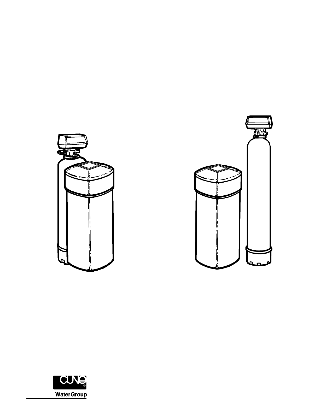
3) Locateincorrectrelationshiptootherwaterconditioning
equipment (Figure 1).
4) Locate the softener in the supply line BEFORE the
water heater. Temperatures above 100°F (38°C) will
damage the softener and void the factory warranty.
5) DoNOTinstallthe softener inalocationwhere freezing
temperatures occur. Freezing may cause permanent
damage and will also void the factory warranty.
6) Allowsufficientspacearoundtheunitforeasyservicing.
7) Provide a non-switched 110/120V, 60Hz power source
for the control.
FACTS TO REMEMBER WHILE PLANNING YOUR IN-
STALLATION:
(1) All installation procedures MUST conform to local and
state plumbing codes.
(2) Iflawnsprinkling,aswimmingpool,orgeothermalheat-
ing/coolingorwaterforotherdevices/activitiesaretobe
treated by the water softener, a larger model MUST be
selectedtoaccommodatethehigherflow rate and soft-
ening demand of these items. The pumping rate of the
wellpumpmustbesufficienttoaccomodatetheseitems
plusthebackwashingrequirementsofthewatersoftener.
Consult your dealer for alternative instructions if the
pumping rate is insufficient.
(3) RememberthatthewatersoftenerINLETisattachedto
thepipethatsupplieswater(i.e.,runstothepump),and
the OUTLET is the line that runs toward the water
heater.
(4) Before commencing the installation it is advisable to
study the existing piping system and to determine the
size, number and type of fittings required.
NOTE: Iftheplumbingsystemisusedasthegroundleg
oftheelectricalsupply,continuityshouldbemaintained
by installing ground straps around any nonconductive
plastic piping used in installation.
(5) Itisalsoadvisabletosweepthefloortoeliminateobjects
that could pierce the brine tank.
(6) SODIUM INFORMATION: Water softeners using so-
diumchlorideforregenerationaddsodiumtothewater.
Persons who are on sodium restricted diets should
consider the added as part of their overall sodium
intake.
1-2

SECTION 2: INSTALLATION
2-1
Step1. Ifnotfactorypre-installed,attachBYPASSVALVE
or YOKE ASSEMBLY using ADAPTER COU-
PLINGS, CLIPS and SCREWS to CONTROL
VALVE (Figure 2). On meter initiated models,
attach METER between BYPASS VALVE and
CONTROL VALVE (Figure 2).
Step 2. On Series 2501 ONLY attach salt grid leg exten-
sions (provided) to bottom of salt grid legs by
snapping nipple on end of extension into hole in
the bottom of the grid leg. NOTE: Extension legs
should be installed whenever salt dosage on any
model softener is 15 lbs. or more. Verify all
packing materials have been removed from the
brine tank. On all units, push salt grid down into
brine tank until grid legs rest on bottom of brine
tank.
Figure 1. INSTALLATION SCHEMATIC
Step3. Shutoffallwateratmainsupplyvalve. Onaprivate
well system, turn off power to pump and drain
pressure tank. Make certain pressure is relieved
fromcompletesystembyopeningnearestfaucetto
drain system. SHUT OFF FUEL SUPPLY TO
WATER HEATER.
Step 4. Cut main supply line as required to fit plumbing to
INLET and OUTLET of unit.
Step5. Attachplumbing. DONOT applyheattoany fitting
connected to BYPASS or CONTROL VALVE as
damage may result to internal parts or connecting
adapters. MAKE CERTAIN WATER FLOW EN-
TERS THROUGH INLET AND DISCHARGES
THROUGH OUTLET.
Figure 2. SOFTENER AND BRINE TANK ASSEMBLY, TOP VIEW

2-2
Step 6. Attach DRAIN LINE to DRAIN LINE FITTING. To
prevent back pressure from reducing flow rate
below minimum required for backwash, DRAIN
LINE MUST be sized according to run length and
relativeheight. Becarefulnottobendflexibledrain
tubingsharplyenoughtocause "kinking" (if kinking
occursDRAINLINEMUSTBEREPLACED). Typi-
calexamplesofproperDRAINLINEdiametersare:
(1) 1/2 in. ID up to 15 ft. when discharge is lower
than INLET.
(2) 5/8 in. ID up to 15 ft. when discharge is slightly
higher than INLET.
(3) 3/4 in. ID when drain is 25 ft. away and/or drain
is installed overhead.
Figure 3. TYPICAL DRAIN
Step 7. Position DRAIN LINE over drain and secure firmly.
To prevent backsiphoning of waste water, provide
an air gap of at least 2 in. or 2 pipe diameters
betweenendofdrainhoseanddrain(Figure3). DO
NOTraiseDRAINLINEmorethan10ft.abovefloor.
Step 8. Connect one end of the 3/8 in. poly line to BRINE
VALVE located on the right side of CONTROL
VALVE. Connect other end to ELBOW inside of
BRINE WELL. Brass insert sleeves and plastic
ferrules must be used where necessary. (Figure 2
and CONTROL VALVE PARTS Drawing, Section
6).
Step 9. InstallOVERFLOWLINEtobrinetankOVERFLOW
FITTING(Figure2). Dischargeoflinemustbelower
thanOVERFLOWFITTING. DONOTINTERCON-
NECT OVERFLOW LINE WITH VALVE DRAIN
LINE.
Step 10. Make certain BYPASS VALVE INLET and OUT-
LETKNOBSAREIN"BYPASS"position. Afterall
plumbingconnectionshavebeencompleted,open
mainwatershut-offvalve or restorepowertowell
pump. Checkforleaksandcorrectasnecessary.
Figure 4. BYPASS VALVE
Step 11. Manually stage control to BACKWASH POSI-
TION by turning "MANUAL REGENERATION
KNOB", clockwise to "BACKWASH" position, re-
fer to HOW TO SET TIME CLOCK REGENERA-
TION CONTROL (Section 3).
Step 12. Partially open INLET valve in plumbing or on
BYPASS VALVE (Figure 4). This will allow the
unittofillslowlyfromthebottomup,eliminatingair
entrapment. Allow unit to fill slowly, failure to do
so could result in loss of resin to the drain. Once
asteadystreamofwater,noair,isflowingtodrain,
the INLET VALVE can be fully opened. The
OUTLET valve can also be opened and the BY-
PASS (if applicable) can be closed. Manually
advance control to SERVICE POSITION. Plug
into anon-switched110/120V,60Hzpowersource.
Step 13. On time clock initiated models, set REGENERA-
TIONFREQUENCY. RefertoREGENERATION
FREQUENCYSCHEDULES(Section3)todeter-
mine correct frequency, then refer to HOW TO
SETTIMECLOCKREGENERATIONCONTROL
(Section 3) for instructions on setting frequency.
Formeterinitiatedmodels,refertoHOWTOSET
METER REGENERATION CONTROL.
NOTE: Regenerationsettingsforbothtimeclock
and meter initiated models are factory preset for
the most efficient salt use and minimum water
consumptionusedforregeneration(aslittleas50
gallons), and conform to the INDUSTRY SALT
EFFICIENCY STANDARDS (required by some
states). REGENERATION FREQUENCY
SCHEDULES are designed for use with factory
regenerationsettings(listedinSPECIFICATIONS
AND OPERATING DATA, Section 5).

The control valve design permits adjustment of
the salt dosage. This adjustment may be neces-
sary when unusual operating conditions exist,
such as high concentrations of iron or hardness
and/orhighflowratesordailywaterconsumption.
Thisadjustmentiseasilyperformedbyloosening
the screw holding the white cam (on backside of
timer) and adjusting the pointer to the desired
pounds of salt.
NOTE: Forsaltdosagesgreaterthan15lbs,grid
legextensionsmustbeattachedtobottomofgrid
legs. For salt dosages less than 15 lbs. DO NOT
use extension legs.
Step 14. SetTIMEOFDAY(refertoappropriateHOW TO
SET TIME CLOCK/METER REGENERATION
CONTROL,Section3). Whenshiftingtodaylight
saving time (and back), you may wish to adjust
TIME OF DAY accordingly.
NOTE: TIMEOFREGENERATIONispre-setfor
2:00a.m.becauseatthistimewaterconsumption
isgenerallyminimal (abuilt-inhardwater bypass
does, however, permit water to be drawn during
regeneration). Shouldyourlifestylerequireregu-
lar use of water during the 2:00 to 3:00 a.m.
regeneration period, or if other water treatment
equipment is also set for 2:00 a.m. regeneration,
theTIMEOFREGENERATIONwill needchang-
ing. To change, adjust time of day on 24-HOUR
GEAR ahead or behind actual time of day. For
example,if1:00a.m.regenerationisdesiredand
actual time of day is 10:00 a.m., advance 24-
HOUR GEAR one hour to 11:00 a.m.; or, should
3:00a.m.regenerationbedesired,setgearback
one hour to 9:00 a.m.
Step 15. Before loading salt, using a pail or garden hose,
add approximately 3 gals. water to brine tank (6
gals.forunitswithextendedgridlegs). Thenadd
initial salt fill to brine tank, and one cup full of
unscented laundry bleach to brine well.
Step 16. Put softener through complete regeneration to
sanitizethesystembeforeuse(RefertoHOWTO
SET TIME CLOCK (or METER) REGENERA-
TION CONTROL for instructions on manual re-
generation). RESTORE FUEL SUPPLY OR
POWER TO WATER HEATER.
Installationisnowcomplete,andyourwater softenerisnow
ready for service!
SPECIAL SERVICE INSTRUCTIONS:
Undernormalcircumstancesremovalofvalveshouldnever
berequired. However,ifitmust beremoved,itcanbedone
by disassembling the quick release clamp, by removing
latch. Pressure should be relieved before attempting any
disassembly. Upon reassembly, all o-rings should be
lubricated with silicone grease. Reassemble clamp as
shown in Figure 5. MAKE SURE ARROWS ON LATCH
SIDE OF CLAMP ARE ALIGNED.
Figure 5. CLAMP ASSEMBLY
2-3

SECTION 3: REGENERATION INSTRUCTIONS
INSTRUCTIONS FOR USING REGENERATION FRE-
QUENCY SCHEDULES:
(Time Clock Initiated Models Only)
(1) DetermineADJUSTEDHARDNESSbyaddingthree(3)
times the iron content in parts per million (ppm) to the
hardness in grains per gallon (gpg). The resulting
number is ADJUSTED HARDNESS.
EXAMPLE: Hardness is 14 gpg and iron is 2 ppm.
ADJUSTED HARDNESS is 20 gpg (14 plus 3 times 2).
(2) Select REGENERATION FREQUENCY SCHEDULE
correspondingtoyourmodel. Locateboxintersectedby
NUMBER IN FAMILY and ADJUSTED HARDNESS (if
3-1
ADJUSTED HARDNESS is between two numbers in
schedule, use higher number). Number in box repre-
sents FREQUENCY or NUMBER OF times per 12
DAYStimershouldbesettoregenerate. RefertoHOW
TO SET TIME CLOCK REGENERATION CONTROL
to set correct frequency.
EXAMPLE: You have Model NS1000, 4 in family and 20
gpg adjusted hardness. Refer to REGENERATION FRE-
QUENCY SCHEDULE for Model Series 1000 and locate
boxintersectedby4infamilyand20gpgadjustedhardness.
The figure "3" in box indicates a REGENERATION fre-
quency of THREE TIMES PER 12 DAYS (if a "1", "2", "4",
etc. were in box, frequencies of once, twice and four times
per twelve days, respectively, would be indicated.)
REGENERATION FREQUENCY SCHEDULES
(TIMES PER 12 DAYS)
MODEL(S) 500 & 501 MODEL(S) 750 & 751
MODEL(S) 1000 & 1001
Persons
In
Family
1
2
3
4
5
6
HARDNESS - GPG
5
1
1
1
1
2
2
10
1
1
2
3
3
4
15
1
2
3
4
4
6
20
1
3
4
6
6
12
25
2
3
4
6
12
12
30
2
4
6
12
12
12
35
2
4
6
12
12
Persons
In
Family
1
2
3
4
5
6
7
8
HARDNESS - GPG
5
1
1
1
1
1
2
2
2
10
1
1
2
2
2
3
3
4
15
1
2
2
3
3
4
6
6
20
1
2
3
4
6
6
6
12
25
1
2
3
6
6
12
12
12
30
2
3
4
6
12
12
12
12
35
2
3
6
6
12
12
12
12
40
2
4
6
12
12
12
12
45
2
4
6
12
12
12
50
2
6
12
12
12
Persons
In
Family
1
2
3
4
5
6
7
8
HARDNESS - GPG
5
1
1
1
1
1
2
2
2
10
1
1
2
2
2
3
3
3
15
1
2
2
3
3
4
4
6
20
1
2
3
3
4
6
6
6
25
1
2
3
4
6
6
6
12
30
2
3
4
6
6
12
12
12
35
2
3
4
6
12
12
12
12
40
2
3
6
6
12
12
12
12
45
2
4
6
12
12
12
12
50
2
4
6
12
12
12
55
2
4
6
12
12
12
60
2
6
12
12
12

REGENERATION FREQUENCY SCHEDULES (Cont'd)
(TIMES PER 12 DAYS)
3-2
MODEL(S): 1500 & 1501
MODEL(S): 2000 & 2001
MODEL(S): 2500 & 2501
Persons
In
Family
1
2
3
4
5
6
7
8
9
10
HARDNESS - GPG
5
1
1
1
1
1
1
1
1
1
1
10
1
1
1
1
1
1
1
2
2
2
15
1
1
1
1
1
2
2
2
2
2
20
1
1
1
2
2
2
2
3
3
3
25
1
1
1
2
2
2
3
3
3
4
30
1
1
2
2
2
3
3
4
4
4
35
1
1
2
2
3
3
4
4
6
6
40
1
2
2
3
3
4
4
6
6
6
45
1
2
2
3
3
4
6
6
6
6
50
1
2
2
3
4
4
6
6
6
12
55
1
2
3
3
4
6
6
6
12
12
60
1
2
3
4
4
6
6
12
12
12
65
1
2
3
4
6
6
6
12
12
12
70
1
2
3
4
6
6
12
12
12
12
75
1
2
3
4
6
6
12
12
12
12
80
2
3
4
6
6
12
12
12
12
12
85
2
3
4
6
6
12
12
12
12
12
90
2
3
4
6
6
12
12
12
12
12
95
2
3
4
6
12
12
12
12
12
100
2
3
4
6
12
12
12
12
12
HARDNESS - GPG
Persons
In
Family
1
2
3
4
5
6
7
8
9
10
5
1
1
1
1
1
1
1
1
1
1
10
1
1
1
1
1
2
2
2
2
2
15
1
1
1
2
2
2
2
3
3
3
20
1
1
2
2
2
3
3
3
4
4
25
1
1
2
2
3
3
4
4
4
6
30
1
2
2
3
3
4
4
6
6
6
35
1
2
2
3
4
4
6
6
6
12
40
1
2
3
3
4
6
6
6
12
12
45
1
2
3
4
4
6
6
12
12
12
50
1
2
3
4
6
6
12
12
12
12
55
1
2
3
4
6
6
12
12
12
12
60
2
3
4
6
6
12
12
12
12
12
65
2
3
4
6
6
12
12
12
12
12
70
2
3
4
6
12
12
12
12
12
75
2
3
4
6
12
12
12
12
12
80
2
3
6
6
12
12
12
12
85
2
3
6
6
12
12
12
12
90
2
4
6
12
12
12
12
Persons
In
Family
1
2
3
4
5
6
7
8
9
10
HARDNESS - GPG
5
1
1
1
1
1
1
1
1
1
2
10
1
1
1
1
2
2
2
2
3
3
15
1
1
1
2
2
3
3
3
4
4
20
1
1
2
2
3
3
4
4
6
6
25
1
2
2
3
3
4
4
6
6
6
30
1
2
3
3
4
6
6
6
12
12
35
1
2
3
4
4
6
6
12
12
12
40
1
2
3
4
6
6
12
12
12
12
45
1
3
4
6
6
12
12
12
12
12
50
2
3
4
6
6
12
12
12
12
12
55
2
3
4
6
12
12
12
12
12
60
2
3
6
6
12
12
12
12
65
2
3
6
6
12
12
12
12
70
2
4
6
12
12
12
12
75
2
4
6
12
12
12
12

HOW TO SET TIME CLOCK REGENERATION CONTROL
HOW TO SET DAYS ON WHICH WATER SOFTENER IS
TO REGENERATE:
Rotate the skipper wheel until the number "1" is at the red
pointer. Setthedaysthatregenerationistooccurbysliding
tabs on the skipper wheel outward to expose trip fingers.
Eachtabisoneday. Fingeratredpointeristonight. Moving
clockwise from the red pointer, extend or retract fingers to
obtain the desired regeneration schedule.
HOW TO SET THE TIME OF DAY:
(1) Press and hold the red button in to disengage the drive
gear.
(2) Turn the large gear until the actual time of day is
opposite the time of day pointer.
(3) Release the red button to again engage the drive gear.
(4) Time of regeneration is preset for 2:00 a.m.
3-3
HOW TO MANUALLY REGENERATE YOUR WATER
SOFTENER AT ANY TIME.
Turn the manual regeneration knob clockwise.
A slight, clockwise movement of the manual regeneration
knob engages the program wheel and starts the regenera-
tion program.
The black center knob will make one revolution in the
followingapproximatelythreehoursandstopintheposition
shown in the drawing (SERVICE POSITION).
Even though it takes three hours for this center knob to
completeonerevolution,theregenerationcycleofyourunit
might be set only one-third of this time.
In any event, conditioned water may be drawn after rinse
water stops flowing from the water softener drain line.

HOW TO SET METER REGENERATION CONTROL
(3) Release the red button to again engage the drive gear.
HOW TO MANUALLY REGENERATE YOUR WATER
SOFTENER AT ANY TIME:
A slight, clockwise movement of the manual regeneration
knob engages the program wheel and starts the regenera-
tion process.
The black center knob will make one revolution in the
followingapproximatelythree hoursandstop intheposition
shown in the drawing.
Even though it takes three hours for this center knob to
completeonerevolution,the regeneration cycleofyourunit
might be set for only one-third of this time.
In any event, conditioned water may be drawn after rinse
water stops flowing from the water conditioner drain line.
NOTE:
The backside of the timer is set the same as the
standard time clock regenerated models.
* Adjusted hardness equals hardness in grains per gallon
(gpg) plust 3 times the iron in parts per million (ppm).
3-4
TYPICAL RESIDENTIAL APPLICATION:
To program, just set the time, set the hardness and it
automaticallymonitorssystemneeds and regeneratesonly
when necessary. To set time of day, press red time set
button and turn 24-hour gear until present time of day is
opposite "time of day arrow." Set program wheel by lifting
the"people"dialandrotating itsothatthenumber ofpeople
in the household is aligned with the grains per gallon water
hardness(adjustedhardness*)scale. Releasethedialand
check for firm engagement at setting. (This method will
provide reserve capacity of one day's supply based on 75
gallons per person.)
OPTIONAL PROGRAMMING PROCEDURE:
Calculate the gallon capacity of the system, subtract the
necessary one day's reserve requirement and set the gal-
lons available opposite the small white dot on the program
wheel gear. Note: drawing shows 850 gallon setting. The
capacity (gallons) arrow denotes remaining gallons exclu-
sive of fixed reserve.
HOW TO SET THE TIME OF DAY:
(1) Press and hold the red button in to disengage the drive
gear.
(2) Turn the large gear until the actual time of day is
opposite the time of day pointer.

SECTION 4: SERVICE INSTRUCTIONS
4-1
PROBLEM CAUSE SOLUTION
1. Hard water,
(unit NOT us-
ing salt; liquid
level in brine
tank NOT too
high).
2. Hard water,
(unitusingsalt;
liquid level in
brinetankNOT
too high).
3. Liquid level in
brinetankTOO
high.
4. System regen-
eratesatwrong
time-of-day.
5. Water continu-
ously flows to
drain.
6. Water tastes
salty.
7. Whitespots on
glassware and
dark surfaces.
8. Low water
pressure (low
flow rate).
9. "Rotten egg"
smell(fromhot
water ONLY).
10. "Rotten egg"
smell (from
both hot and
cold water).
11. Loss of resin
through drain
line.
A. Electrical service to unit inter-
rupted.
B. Timer not working.
C. Timer improperly set.
D. Safety brine valve not opening.
E. Salt "bridged" in brine tank.
A. Bypass open.
B. Timer improperly set.
C. No salt in brine tank.
D. Excessive water usage.
E. Unit installed backwards.
F. Unit undersized.
A. Brine valve not closing.
B. Salt setting too high.
C. Injector screen plugged.
D. Drain line frozen, plugged or re-
stricted.
E. Salt "mushed" or sand from salt
plugging bottom of brine tank.
F. Incorrect brine line flow control
(BLFC).
A. Power outage occurred.
A. Foreignmaterialincontrolvalve.
B. Internal control leak.
C. Controlvalvejammedinbrineor
backwash position.
A. Salt setting too high.
B. Cyclone (distributor) tube too
short.
A. Sodium residual resulting from
water having very high hard-
ness or total dissolved solids
(TDS).
A. Ironbuild-upinlinetowatercon-
ditioner.
B. Iron build-up in water condi-
tioner.
C. Well pumping sand.
D. Pump losing capacity.
A. Magnesium rod in water heater.
A. Hydrogensulfide("sulfur")inwa-
ter supply.
B. Bacterial iron in water supply.
C. Algae in water supply.
A. Air in water system.
B. Incorrect Drain Line Flow Con-
trol (DLFC).
A. Assure permanent electrical service (check fuse, plug,
pull chain or switch.)
B. Replace timer motor.
C. Increase frequency of regeneration and/or salt setting.
D. Replace safety brine valve.
E. Breakup salt.
A. Close bypass (replace if necessary).
B. Increase frequency of regeneration, or reset timer if
needed.
C. Add salt; maintain above water level.
D. Increase frequency of regeneration and/or salt setting
(See HOW TO SET TIMER).
E. Reinstall unit.
F. Replace with larger unit.
A. Replace brine valve.
B. Reset timer.
C. Clean injector and screen.
D. Free drain.
E. Clean out brine tank (See Instructions).
F. Replace with correct flow control (See Specifications).
A. Reset timer.
A. Remove piston assembly and inspect bore; remove
foreign material and check control in various regenera-
tion positions.
B. Replace seals and/or piston assembly.
C. Replace piston, seals and spacers.
A. Reset program cycle.
B. Replace.
A. Installation of additional water treatment equipment
such as reverse osmosis or demineralization.
A. Clean line to water conditioner.
B. Cleancontrol andadd Iron-X™Mineral Cleanerto resin
bed; increase frequency of regeneration.
C. Install sand trap.
D. Contact pump repair service.
A. Replace with aluminum rod or remove.
A. Install Sulfur Removal System.
B. Install Chem-Free™ Iron Removal System.
C. Pour approximately 1/2 cup laundry bleach into brine
well just before regeneration as frequently as neces-
sary.
A. Assure that well system has proper air eliminator con-
trol; check for dry well condition.
B. Replace with correct DLFC.

SECTION 5: SPECIFICATIONS AND OPERATING DATA
TIMER INITIATED MODELS:
NOTES:
(1) Actual capacity may vary substantially depending on
water analysis and operating conditions. Softening
capacities for systems containing 0.5 and 0.75 cubic
feet are based on SOFTENING PERFORMANCE,
systemscontaining1.0cubicfeetandlargerarebased
on Radium 226/228, Barium and Softening.
(2) For satisfactory performance indicated flow rates and
durationshouldnotbeexceeded. Flowratesspecified
are adequate for normal residential applications. Do
not use Service Flow Rate when sizing commercial
applicationsoriftreatedwateristosupplyageothermal
heatpump,swimmingpool,etc.(contactdealerbefore
selectingequipment).
5-1
Maximum operating temperature 100°F (38°C); Electrical requirements 110V/60Hz (220V/50Hz); Operating pressure 20-
125psi. Alltypeswatersoftenersaltmaybeused(SeeMAINTENANCE). Specificationssubjecttochangewithoutnotice.
(3) For system to operate properly, pumping rate of well
pump MUST be sufficient to backwash unit at rate
specified.
(4) Model numbers ending with "1" are 1 in.; those ending
with "0" are 3/4 in. Example: NS1001 becomes
NS1000.
ITEM
System Style:
Nominal Media Volume, cu. ft.
Salt dosage, lbs.:
Factory Setting
Maximum Setting
Nominal Softening Capacity,
grains: (1)
At factory salt setting
At maximum salt setting
Operating Flow Rates, gpm: (2)
Continuous (no duration limit)
Service (10 minutes or less)
Pressure Loss @ Operating Flow
Rates, psi:
Continuous
Service
Regeneration Flow Rates, gpm:
Backwash (3)
Brine/Rinse
Rapid Rinse
Brine Refill
Inlet/Outlet Pipe Size, in.
Mineral Tank Dia. x Height, in.
Overall Depth & Height w/Control
Valve, in.
Brine Tank, W x D x H, in.
Approx. Salt Storage, lbs.
Approx. Shipping Weight, lbs.
NS0751
0.75
6.0
12.0
21,450
22,500
3.0
6.0
6.0
10.0
1.2
0.26
1.2
0.5
3/4 or 1
7x44
15x51
15x15x34
160
75
NS1001
1.0
6.0
15.0
18,600
30,000
4.0
7.0
6.0
15.0
1.5
0.33
1.5
0.5
3/4 or 1
8x44
15x51
15x15x34
160
89
NS1501
1.5
9.0
24.0
27,900
45,000
6.0
8.0
8.0
15.0
2.4
0.33
2.4
0.5
3/4 or 1
10x44
15x51
15x15x34
160
116
NS2501
2.5
15.0
24.0
46,500
60,000
9.0
10.0
11.0
15.0
3.5
0.64
3.5
0.5
3/4 or 1
12x54
15x61
15x15x34
160
187
NLS0501
0.5
6.0
8.0
14,300
15,000
2.0
4.0
5.0
8.0
1.2
0.26
1.2
0.5
3/4 or 1
7x35
15x42
15x15x34
160
59
NLS0751
0.75
6.0
12.0
21,450
22,500
3.0
6.0
6.0
10.0
1.5
0.33
1.5
0.5
3/4 or 1
8x35
15x42
15x15x34
160
74
NLS1001
1.0
6.0
15.0
18,600
30,000
4.0
7.0
6.0
15.0
2.0
0.33
2.0
0.5
3/4 or 1
10x35
15x42
15x15x34
160
85
NS2001
2.0
12.0
24.0
37,200
54,000
7.0
8.5
9.0
15.0
2.4
0.33
2.4
0.5
3/4 or 1
10x54
15x61
15x15x34
160
141
SPACEMAKERTWO TANK

METER INITIATED MODELS:
NOTES:
(1) Dial settings based on this capacity. Consult dealer
before changing salt dosage.
(2) Actual capacity may vary substantially depending on
water analysis and operating conditions. Softening
capacities for systems containing 0.5 and 0.75 cubic
feet are based on SOFTENING PERFORMANCE,
systemscontaining1.0cubicfeetandlarger arebased
on Radium 226/228, Barium and Softening.
(3) For satisfactory performance indicated flow rates and
durationshouldnot be exceeded. Flowratesspecified
are adequate for normal residential applications. Do
not use Service Flow Rate when sizing commercial
applicationsoriftreatedwateristosupplyageothermal
heatpump,swimmingpool, etc. (contactdealerbefore
selectingequipment).
5-2
Maximumoperatingtemperature100°F(38°C);Electricalrequirements110V/60Hz(220V/50Hz);Operatingpressure20-
125psi. Alltypeswatersoftenersaltmaybeused(SeeMAINTENANCE). Specificationssubjecttochangewithoutnotice.
ITEM
System Style:
Nominal Media Volume, cu. ft.
Salt dosage, lbs.:
Factory Setting (1)
Maximum Setting
Nominal Softening Capacity,
grains:(2)
At factory salt setting
At maximum salt setting
Operating Flow Rates, gpm: (3)
Continuous (no duration limit)
Service (10 minutes or less)
Pressure Loss @ Operating Flow
Rates, psi:
Continuous
Service
Regeneration Flow Rates, gpm:
Backwash (4)
Brine/Rinse
Rapid Rinse
Brine Refill
Inlet/Outlet Pipe Size, in. (5)
Mineral Tank Diameter x Height, in.
Overall Depth & Height w/Control
Valve, in.
Brine Tank, W x D x H, in.
Approx. Salt Storage, lbs.
Approx. Shipping Weight, lbs.
NSM0751
0.75
6.0
12.0
21,450
22,500
3.0
6.0
6.0
10.0
1.2
0.26
1.2
0.5
3/4 or 1
7 x 44
17 x 51
15x15x34
160
76
NSM1001
1.0
6.0
15.0
18,600
30,000
4.0
7.0
6.0
15.0
1.5
0.33
1.5
0.5
3/4 or 1
8 x 44
17 x 51
15x15x34
160
90
NSM1501
1.5
9.0
24.0
27,900
45,000
6.0
8.0
8.0
15.0
2.4
0.33
2.4
0.5
3/4 or 1
10 x 44
17 x 51
15x15x34
160
117
NSM2501
2.5
15.0
24.0
46,500
60,000
9.0
10.0
11.0
15.0
3.5
0.64
3.5
0.5
3/4 or 1
12 x 54
17 x 61
15x15x34
160
188
NLSM0751
0.75
6.0
12.0
21,450
22,500
3.0
6.0
6.0
10.0
1.5
0.33
1.5
0.5
3/4 or 1
8 x 35
17x 42
15x15x34
160
75
NLSM1001
1.0
6.0
15.0
18,600
30,000
4.0
7.0
6.0
15.0
2.0
0.33
2.0
0.5
3/4 or 1
10 x 35
17 x 42
15x15x34
160
86
NSM2001
2.0
12.0
24.0
37,200
54,000
7.0
8.5
9.0
15.0
2.4
0.33
2.4
0.5
3/4 or 1
10 x 54
17 x 61
15x15x34
160
142
SPACEMAKERTWO TANK
(4) For system to operate properly, pumping rate of well
pump MUST be sufficient to backwash unit at rate
specified.
(5) Model numbers ending with "1" are 1 in. those ending
with "0" are 3/4 in. Example: NSM1001 becomes
NSM1000.

6-1
SECTION 6: PARTS
COMPONENT PARTS LIST
TWO TANK MODELS (NS & NSM SERIES)
NOTE: When ordering components, always specify model number.
REF
NO.
1
2
3
4
5
6
7
8
9
10
11
12
13
14
15
16
17
18
19
DESCRIPTION
Control Valve, Time Clock Initiation, with
Cover, less Bypass (NS Series)
Control Valve, Meter Initiation, with
Cover, less Bypass (NSM Series)
Adapter Assy., Flg-Thrd (Incl. Ref. 3)
O-Ring
Clamp Assy. (Incl. Ref. 5)
Latch, Clamp
Media Tank w/Base (Incl. Ref. 9)
Media
Cyclone Assy.
Tank Base
Brine Line Tubing
Brine Tank, Complete
Brine Tank, Complete w/Extension Kit
Overflow Fitting
Brine Tank Shell w/Cover
Brine Well w/Cap
Grid Plate
Grid Plate w/Extension Kit
Safety Brine Valve, Complete
Safety Brine Valve
Float Assembly
Air Check Assembly
NS0751
NSM0751
N100120-5R
N12J120-5R
FA45TX
ORG-234
FC45XX
FC45C
MTP0744FB
H-075P
C04N-44
T06-7P
13000X
BT1534X
--
BT16
BT1534L
BT15BW
BT15GP
--
BT15SBVA
60014
60068X
60002
NS1001
NSM1001
N100150-5W
N12J150-5W
FA45TX
ORG-234
FC45XX
FC45C
MTP0844FB
H-10P
C04N-44
T06-8P
13000X
BT1534X
--
BT16
BT1534L
BT15BW
BT15GP
--
BT15SBVA
60014
60068X
60002
NS1501
NSM1501
N100240-5W
N12N240-5W
FA45TX
ORG-234
FC45XX
FC45C
MTP1044FB
H-10P
& H-050P
C04N-44
T06-10P
13000X
BT1534X
--
BT16
BT1534L
BT15BW
BT15GP
--
BT15SBVA
60014
60068X
60002
NS2001
NSM2001
N100240-5W
N12R240-5W
FA45TX
ORG-234
FC45XX
FC45C
MTP1054FB
H-10P(x2)
C04N-54
T06-10P
13000X
--
BT1534X-EXT
BT16
BT1534L
BT15BW
--
BT15GP-EXT
BT15SBVA
60014
60068X
60002
NS2501
NSM2501
N100350-5W
N12U350-5W
FA45TX
ORG-234
FC45XX
FC45C
MTP1254FB
H-10P(x2)
& H-050P
C04N-54
T06A-12P
13000X
--
BT1534X-EXT
BT16
BT1534L
BT15BW
--
BT15GP-EXT
BT15SBVA
60014
60068X
60002

6-2
NOTE: When ordering components, always specify model number.
REF
NO.
1
2
3
4
5
6
7
8
9
10
11
12
13
14
15
16
17
18
19
DESCRIPTION
Control Valve, Time Clock Initiation, with Cover,
less Bypass (NLS Series)
Control Valve, Meter Initiation, with Cover, less
Bypass (NLSM Series)
Adapter Assy., Flange-Thread (Incl. Ref. 3)
O-Ring
Clamp Assy. (Incl. Ref. 5)
Latch, Clamp
Media Tank w/Base (Incl. Ref. 9)
Media
Cyclone Assy.
Tank Base
Brine Line Tubing
Brine Tank, Complete
Brine Tank Shell w/Cover
Brine Well w/Cap
Overflow Fitting
Grid Plate
Safety Brine Valve, Complete
Safety Brine Valve
Float Assembly
Air Check Assembly
NLS0501
N100120-5R
N/A
FA45TX
ORG-234
FC45XX
FC45C
MTP0735FB
H-050P
C04N-35
T06-7P
13000X
BT1534X
BT1534L
BT15BW
BT16
BT15GP
BT15SBVA
60014
60068X
60002
NLS0751
NLSM0751
N100150-5W
N12J150-5W
FA45TX
ORG-234
FC45XX
FC45C
MTP0835FB
H-075P
C04N-35
T06-8P
13000X
BT1534X
BT1534L
BT15BW
BT16
BT15GP
BT15SBVA
60014
60068X
60002
NLS1001
NLSM1001
N100240-5W
N12J240-5W
FA45TX
ORG-234
FC45XX
FC45C
MTP1035FB
H-10P
C04N-35
T06-10P
13000X
BT1534X
BT1534L
BT15BW
BT16
BT15GP
BT15SBVA
60014
60068X
60002
COMPONENT PARTS LIST
SPACE-MAKER MODELS (NLS & NLSM SERIES)

CONTROL VALVE
- 12 DAY TIMER
6-3

A
B
C
D
E
F
G
H
J
K
L
1
26
27
29
36
37
50
51
61
62
63
65
66
67
68
69
70
71
72
73
78
79
80
81
82
83
84
85
88
DESCRIPTIONPART NO.REF.
60353-13
14381X
13010X
13168-36X
14449-00X
60102-00
60125
60084-50X
60022-50
10090X
60049/18706X
60049/18706-02X
22601X
18743
11384
13170
13547
11842
13304
12281
13497
12638
13301
10914
10227
10913
13303
13166
13315
12085
12086
12088
12090
13173
12338
12767
10332
10330
10329
13305
13709
13255
13314
18706
18706-02
ONLY THOSE PARTS CIRCLED IN DRAWING AND/OR LISTED BELOW ARE STOCK ITEMS
ALL OTHERS ARE SPECIAL ORDER, NON-RETURNABLE
PARTS LIST - 12 DAY TIMER
Power Head Assy., Complete, L/Cover, NS/NLS Series (Incl. Ref. Items 2-37)
Skipper Wheel Assy. (Incl. Ref. Items 4-10)
24-Hour Gear Assy. (Incl. Ref. Items 11-17)
Brine Cam Assy. 6-36 lb. Salt (Incl. Ref. Items 10, 30 through 35)
Control Valve Body Assy. (Incl. Ref. Items 38-81)
Piston Kit (Incl. Ref. Items 42-46)
Seal Kit (Incl. Ref. Items 47 & 48)
Brine Valve Assy., 0.50 GPM (Incl. Ref. Items 52-81)
Brine Line Flow Control Assy., 0.50 GPM, (Incl. Ref. Items 74-77)
Adapter Coupling Assy. (Incl. 2 ea. Ref. Items 83-85 & 4 ea. Item 82)
1" Bypass Valve Assy.
3/4" Bypass Valve Assy. (Optional)
Valve Cover, Specify Model
Motor, 120v/60 Hz
Motor Mtg. & Ground Screw
Main Gear
Strain Relief
Power Cord, 110V 60Hz
Distributor Tube O-Ring
Tank O-Ring
Air Disperser
Drain O-Ring
Injector O-Ring
Injector Throat - Specify Size
Injector Screen
Injector Nozzle - Specify Size
Injector Cover O-Ring
Injector Cover
Injector Mounting Screw
Drain Line Flow Control Button:
1.2 GPM (0501 & 0751 Two Tank)
1.5 GPM (0751 Space-Maker, 1001 Two Tank)
2.4 GPM (1001 Space-Maker, 1501 & 2001 Two Tank)
3.5 GPM (2501 Two Tank)
Drain Line Flow Control Retainer
Drain Line Fitting
Brine Line Screen
Brine Line Tube Insert
Brine Line Ferrule
Brine Line Fitting Nut
Adapter Coupling O-Ring
Adapter Coupling
Adapter Clip
Adapter Coupling Screw
Adapter Yoke, 1" NPT
Adapter Yoke, 3/4" NPT
6-4

CONTROL VALVE
- METER INITIATED
6-5

ONLY THOSE PARTS CIRCLED IN DRAWING AND/OR LISTED BELOW ARE STOCK ITEMS
ALL OTHERS ARE SPECIAL ORDER, NON-RETURNABLE
PARTS LIST - METER TIMER
6-6
A
B
C
D
E
F
G
H
J
K
L
1
23
24
27
38
39
40
53
54
65
66
67
68
69
70
71
72
73
74
75
76
81
82
83
84
90
91
92
93
102
DESCRIPTIONPART NO.REF.
60354-13
14039X
13010X
13168-36X
14449-00X
60102-00
60125
60084-50X
60022-50
60086
60049/18706X
60049/18706-02X
22601X
18743
11384
13170
14043
13547
11842
13304
12281
13497
12638
13301
10914
10227
10913
13303
13166
13315
12085
12086
12088
12090
13173
13308
12767
10332
10330
10329
13314
13255
13821
13305
18706
18706-02
Power Head Assy., Complete, L/Cover, NSM/NLSM Series (Incl. Ref. Items 2-40)
Program Wheel Assy. (Incl. Ref. Items 4-7, Specify "K" Label or Model)
24-Hour Gear Assy. (Incl. Ref. Items 8-14)
Brine Cam Assy. 6-36 lb. Salt (Incl. Ref. Items 26, 28-33)
Control Valve Body Assy. (Incl. Ref. Items 41-84)
Piston Kit (Incl. Ref. Items 45-49)
Seal Kit (Incl. Ref. Items 50 & 51)
Brine Valve Assy., 0.50 GPM (Incl. Ref. Items 55-84)
Brine Line Flow Control Assy., 0.50 GPM, (Incl. Ref. Items 77-80)
Meter Assy. (Incl. Ref. Items 85-93)
1" Bypass Valve Assy.
3/4" Bypass Valve Assy. (Optional)
Valve Cover, Specify Model
Motor, 120v/60 Hz
Motor Mtg. & Ground Screw
Main Gear
Flexible Cable
Strain Relief
Power Cord, 110V/60Hz
Distributor Tube O-Ring
Tank O-Ring
Air Disperser
Drain O-Ring
Injector O-Ring
Injector Throat - Specify Size
Injector Screen
Injector Nozzle - Specify Size
Injector Cover O-Ring
Injector Cover
Injector Mounting Screw
Drain Line Flow Control Button:
1.2 GPM (0751 Two Tank)
1.5 GPM (0751 Space-Maker, 1001 Two Tank)
2.4 GPM (1001 Space-Maker, 1501 & 2001 Two Tank)
3.5 GPM (2501 Two Tank)
Drain Line Flow Control Retainer
Drain Line Fitting
Brine Line Screen
Brine Line Tube Insert
Brine Line Ferrule
Brine Line Fitting Nut
Adapter Coupling screw
Adapter Clip
Meter Body
Meter Body O-ring
Adapter Yoke, 1" NPT

REPLENISHMENT OF SALT SUPPLY:
The salt storage capacity of the brine tank is approximately
160lbs. Duringeachregeneration aspecificamountof salt
is consumed, thus requiring its periodic replenishment (the
frequency is dependent on the regeneration schedule).
Always replenish salt before the supply is exhausted to
assure a continuous supply of softened water.
TYPE OF SALT TO USE:
Any type of water softener salt may be used. There are
advantagesanddisadvantagestoeverytypeofsalt. Please
askyourlocaldealerforhisadvice. Yourunitisdesignedto
compensate for the disadvantages.
BRINE TANK CLEAN-OUT:
To prevent service problems the brine tank should be
emptied and flushed out with a garden hose when dirt and
other insolubles accumulate. The clean-out frequency de-
pends on the type salt used and regeneration frequency.
The clean-out should be done when the salt level is low.
Steps to follow:
(1) Disconnect brine line at either end.
(2) Turn brine tank upside down and discard old
salt.
(3) Rinse out with a garden hose.
(4) Reconnect brine line.
(5) Addabout3gals.ofwater(6gals.forunits with
extended grid legs) to brine tank before adding
newsalt. Performapproximatelyonceayearif
rock salt is used; with other types of salt, ap-
proximately once every other year.
SECTION 7: MAINTENANCE
7-1
PREVENTING IRON-FOULING OF MINERAL BED:
Ifironispresentinthewatersupply,thesoftenermineralbed
will eventually become iron-fouled, resulting in reduced
softening capacity and rust-stained fixtures. Mixing one to
twoouncesofIRON-X™ MineralCleanerwithevery 80lbs.
ofsaltaddedtobrinetankwillminimizetheseproblemsfrom
occurring. IRON-X™ is available from your dealer.
PERIODICALLY CHECK TIME OF DAY SETTING:
Power outages will cause TIME OF DAY timer setting to
become incorrect. To reset, refer to appropriate HOW TO
SET TIME CLOCK (or METER) REGENERATION CON-
TROL, Section 3.
MALFUNCTION OF UNIT:
Your water softener, under normal conditions, should pro-
vide years of trouble-free service; however, since it is a
mechanical device, it can malfunction. (Refer to Section 4,
SERVICE INSTRUCTIONS, if necessary).
CHANGE OF OPERATING CONDITIONS:
Should your family size, your water usage habits, or your
water quality change, the regeneration program settings
may have to be adjusted. Consult your dealer if any of the
above occur.
This manual suits for next models
29
Other Cuno Water Dispenser manuals
Popular Water Dispenser manuals by other brands

Vertiv
Vertiv Liebert CW440 Installer/user guide

Murdock
Murdock A611108F-G Installation & maintenance instructions

Kenmore
Kenmore 625.388270 owner's manual

Elkay
Elkay EZH2O EZSTLG8WS 1B Series Installation & use manual

Bunn
Bunn Easy Clear ED-12-HB specification

Halsey Taylor
Halsey Taylor HVR8BL*1D owner's manual