BENDER MOUNTING PROCEDURE
1. Determine the correct size support pins for the bender you are using:
Bender Model # Support Pin Size
Greenlee®880 –3/4”diameter pins
Greenlee®777 –1”diameter pins
Greenlee®884, 885 –1 1/2”diameter pins
Ensley®E –125 –1 1/2”diameter pins
NOTE: The support pins for the 884 and 885 Benders have 2 retaining ring
grooves. Place the retaining ring in the outer groove when using the
885 Bender and place the retaining ring in the inner groove when using
the 884 Bender. See figure below.
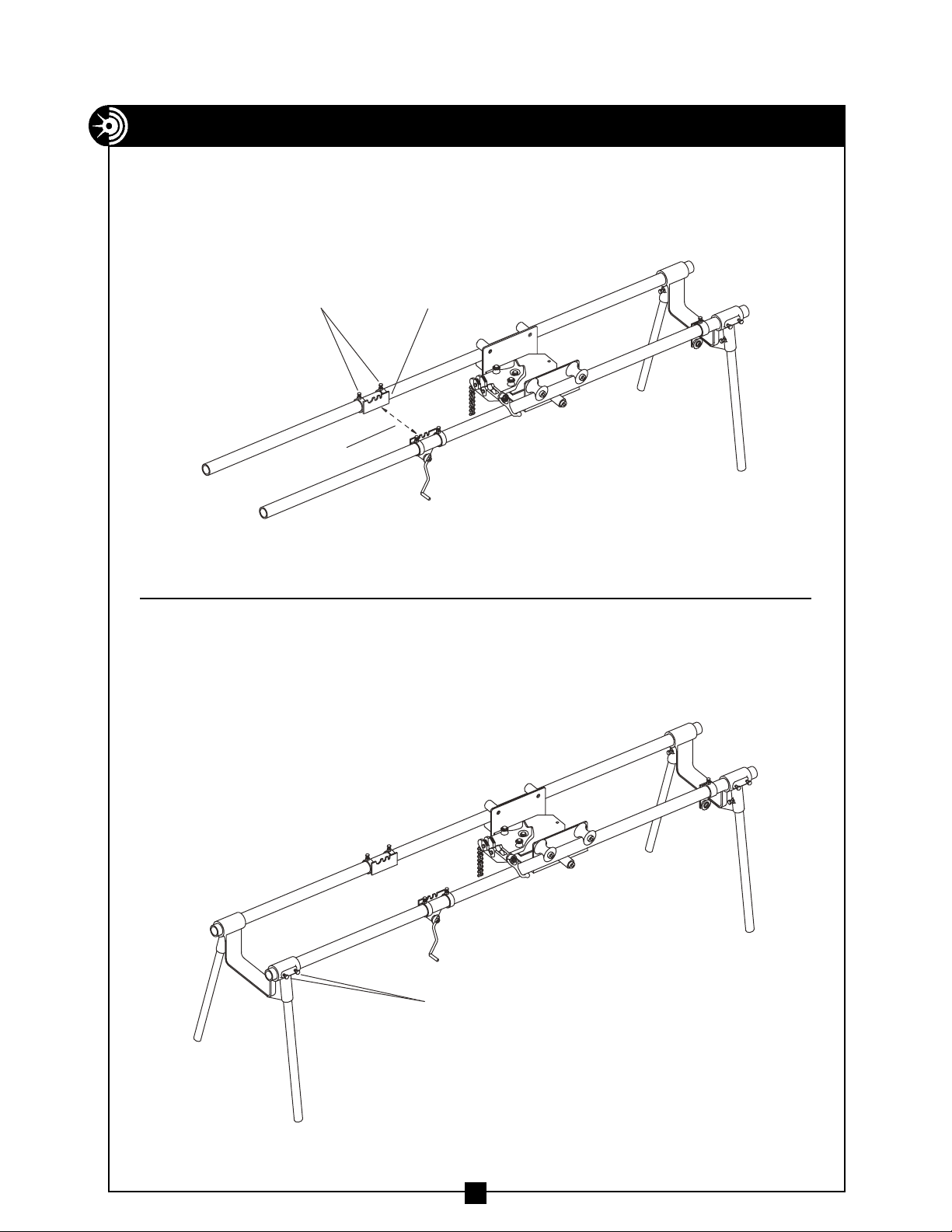
2. Place support pins into the bender frame holes that match the size
conduit to be bent. ( Note: Be sure the ram scale is on the hand crank
unit side of the bending table. )
3. Lift bender and set on table as shown with one (front) support pin about
1”from leg support. See figure 7. Next, move the hand crank unit and
the rest plate so that the rear support pin sits in the matching slot of
the hand crank unit and the rest plate. The wide groove on each side of
the support pin should ”sit“in the rest plate and the hand crank unit.
See figure 7. Tighten all bolts on the hand crank unit and the rest plate.
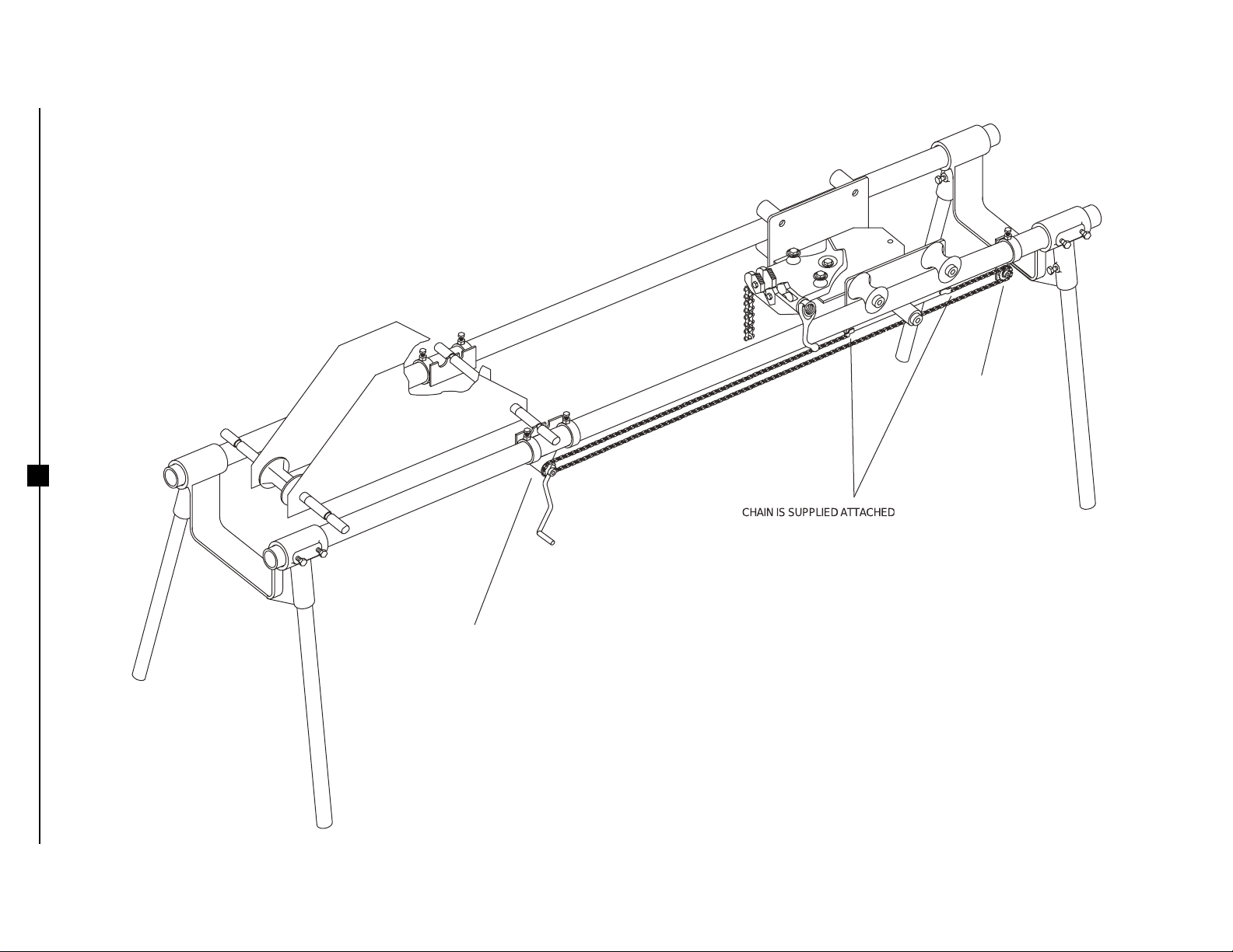
4. Place chain around sprocket on hand crank unit and around idler unit as
shown. See figure 8. Adjust idler unit to tighten chain. Tighten bolt on
idler unit.
NOTE: Before bending, check to ensure all bolts are tightened and the
bending table is level.
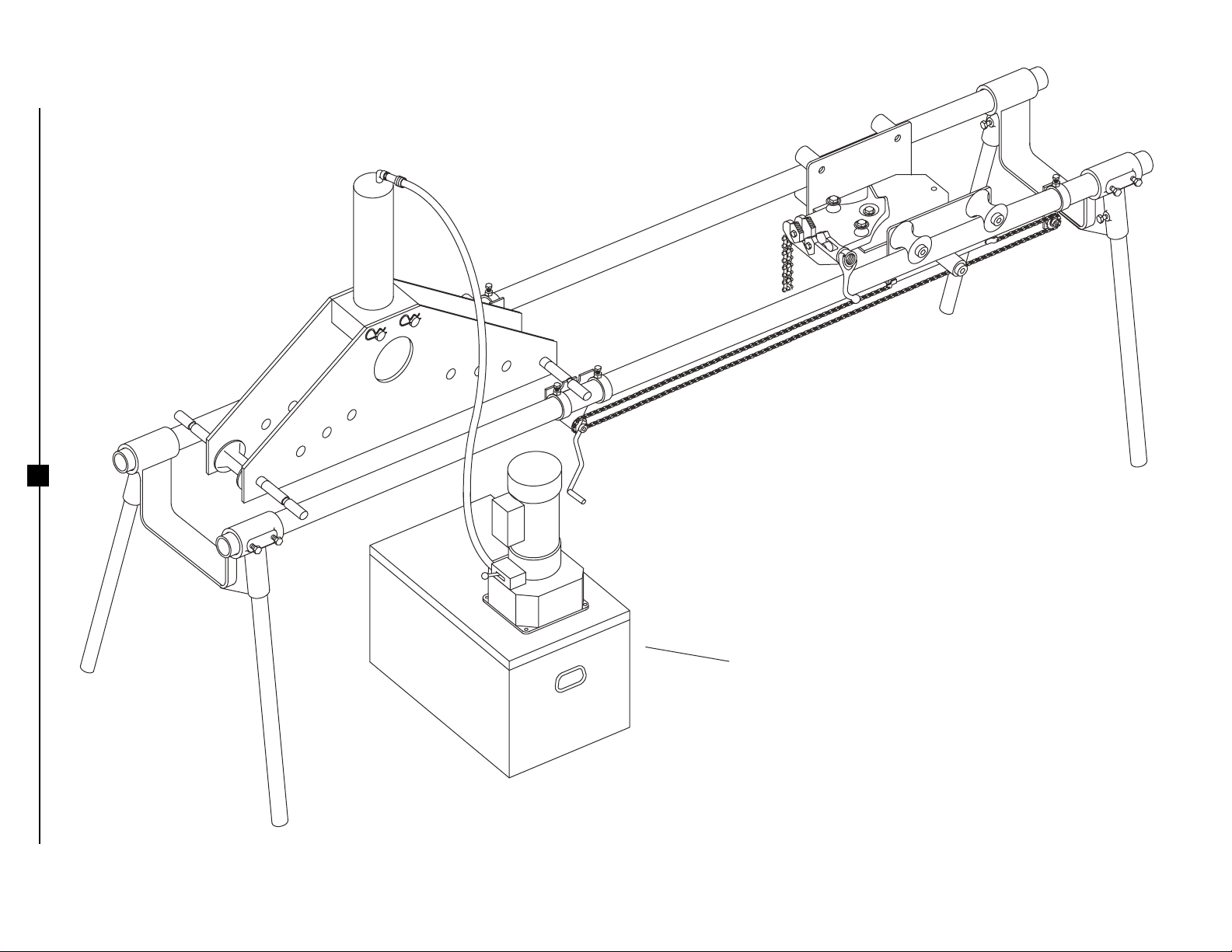
5. The Bending Table is now set-up for bending radii up to 36".
NOTE: When bending 36" and larger radii and to bend 3" and smaller
conduit with the Greenlee®884 and 885 benders, the chain extension kit
( CurrentTools part # 280-9 ) is required.
6
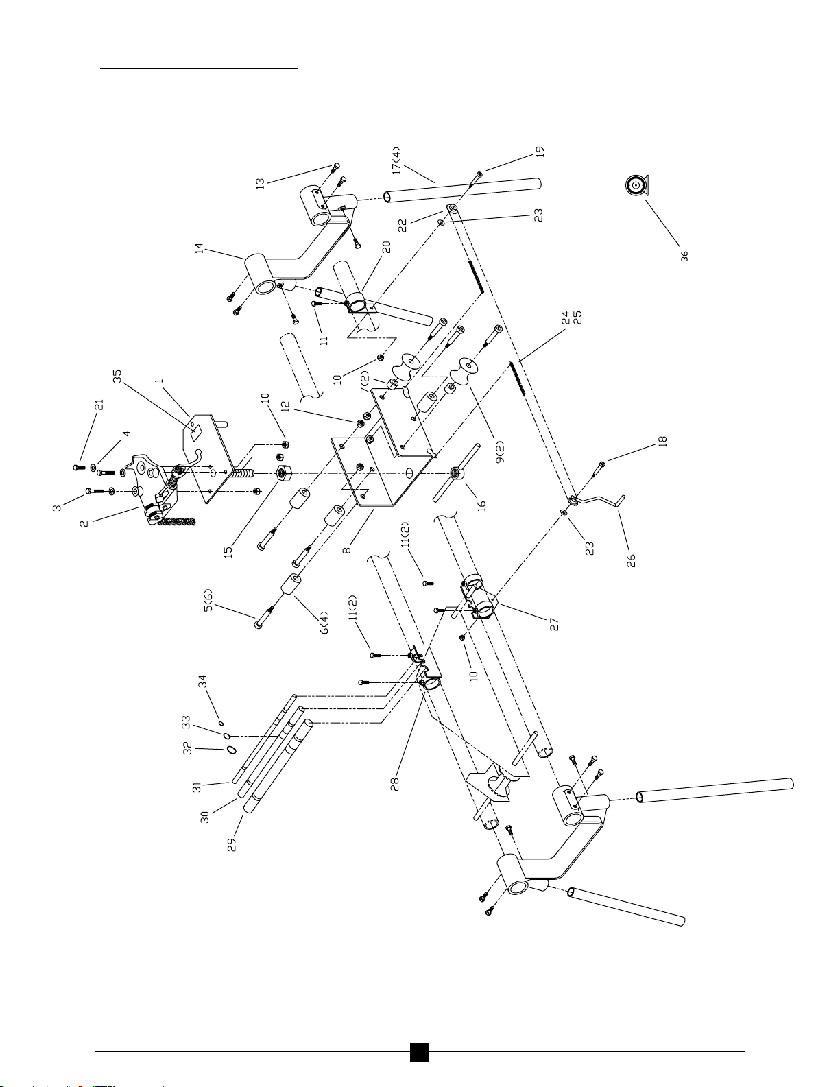
The 280 BendingTable
comes standard with the
1 1/2”diameter pins.
*Greenlee®is a registered trademark of
Greenlee/Textron and Ensley®is a registered
trademark of Rothenberger Group, which
have no affiliation with CurrentTools.