manuals.online logo
Brands
  1. Home
  2. •
  3. Brands
  4. •
  5. Current
  6. •
  7. Aquarium
  8. •
  9. Current LOOP 4300 User manual

Current LOOP 4300 User manual

Each LOOP Marine Bundle Kit includes:
Item Description
A LOOP® Power Center (Pre-Assembled) 1 1 1
BOrbit™ Marine IC PRO LED (2 Lights) 1x36" 1x48" 1x72"
C eFlux™ Wave Pumps 2x1050 gph 2x1050 gph 2x2100 gph
D eFlux™ DC Flow Pump 1x1900 gph 1x1900 gph 1x3170 gph
EOrbit™ Adjustable Tank Mount Bracket 2 2 2
Additional Help
AB
CD
E
Note:
If your LOOP®Bundle is missing any part, please contact us directly at www.current-usa.com
DO NOT RETURN TO RETAILER
LOOP® Marine Bundle Kit
What’s Included
For additional installation instructions and videos, please visit our website at www.current-usa.com
P1P3 P2 L1L2
Model 4300, 4301, 4302
NOTE: READ ALL SAFETY INSTRUCTIONS
INCLUDED WITH EACH PRODUCT
Register your product at www.current-usa.com/support/product-registration. Enter your
personal information, choose "LOOP Marine Bundle" and use the model number for the
serial number (#4300, #4301, #4302)
Page 1
Items Included
Model #4300 Model #4301 Model#4302
36" Bundle Kit 48" Bundle Kit 72" Bundle Kit
Qty. 1
Qty. 1
Qty. 2
Qty. 2
Qty. 2
F
Step 1. Install the Power Center
1. Unpack Power Center box and remove components and mounting hardware. Each Power
center box should include the following:
1 x Power Center (Pre-Assembled)
1 x LOOP® IC Controller, IR Remote, IR Cable & Mounting Hardware
1 x Surge Protector Power Strip
1 x Mounting Hardware Kit:
1 x Velcro Strip
4 x Wood Mounting Screws
2 x Cable Holders w/Mounting Screws
2 x Cable Tie Wraps
2. Check all DC cables, microUSB cables and
AC plugs on transformers and ensure all are
firmly plugged in.
3. Locate where the Power Center will be installed. The minimum space required is:
16.5"L x 7"W x 13"H. The surface must be flat and in a dry location protected from water and
salt creep. It MUST be mounted to a surface in a vertical position, DO NOT set Power Center on
stand floor due to a risk of water damage. We recommend the following locations:
Power Center Installation
IMPORTANT: Before installing, read ALL SAFETY INSTRUCTIONS and WARNINGS
Quick Start Guide
LOOP® Marine Bundle Kit
P1P3 P2 L1L2
Stand Side Walls
Stand Back Panel
DO NOT REST
ON STAND FLOOR
Ensure all cables
are plugged in
2
3Location
Page 2
4. Install Velcro strip to bottom of surge protector. Attach surge protector to bottom shelf on
Power Center, ensuring the cable is located in the right direction for easy plug in (determined
location and cable access location on stand.)
5. Plug the four DC power supplies into surge protector.
6. Install cable tie mounts to side panels of power
center using the flat mounting screws and wing nuts.
There are 4 locations for the mounting the 2 included
cable tie mounts on the Power Center. These can be
used to wrap and organize excess cable from the LED
lights or wave pumps.
7. Use the template below to pre-install the mounting
screws for the power center. Use a pencil to mark
mounting holes - square 15" wide x 10-1/8 high.
Power Center Installation
LOOP® Marine Bundle Kit
P1
P3
P2
L1
L2
P1P3 P2 L1L2
15"
15"
10-1/8"
10-1/8"
8. Use a small drill and drill a small hole fr screw insertion.
CAUTION: Do not to drill through entire stand wall.
Using a small Phillips head screwdriver, install the four
wood mounting screws.Leave 1/4" of screw offset for
Power Center installation.
1/4" Offset
6Install 2 cable
tie mounts
4Install surge protector
using velcro
5Plug power supplies
into surge protector
7Mark mounting holes for power center
15" Wide x 10-1/8" High
8Install screws and
leave 1/4" offset
Page 3
9. Plug the LOOP® IC controller into Port #1 on
the Orbit IC manifold HUB. If using the optional
remote IR sensor, plug into Port #2.
10. Use either the velcro tape included with the
LOOP® IC controller or install the controller
mounting bracket to the desired location
following the included instructions.
11. Unpack IR remote and remove clear tab
located at the bottom of the remote. Press
the red POWER key located in the top
right corner and ensure to ensure the
controller and remote are communicating.
12. Plug surge protector into a GFCI protected outlet and ensure drip loop is in place. CAUTION:
This product MUST be plugged into a GFCI protected outlet.
13. Toggle the surge protector POWER switch to the ON
position. Ensure the green indicator lights on all power
supplies illuminate and the LOOP® IC controller and
HUB indictor lights all turn On.
14. Install Power Center to stand wall by squeezing each
side of the Power Center inwards and aligning the
mounting slots with the wood mounting screws.
Power Center should flex out when released and be
mounted to stand wall. (See below)
Power Center Installation
P1P3 P2 L1L2
LOOP® Marine Bundle Kit
!"
PORT #2
IR Sensor
(Optional) PORT #2
LOOP® IC
Controller
Orbit Marine IC
Manifold HUB
eFlux Wave Pump
Manifold HUB
eFlux DC Pump
Manifold HUB
! " #
POWER
Remove
clear tab
AC Power
GFCI Outlet
Use only with GFCI
Protected AC Outlet
Ensure use of drip
loop for all cables
Surge Protector
P1P3 P2 L1L2 P1P3 P2 L1L2
+Wood
Screw
+Wood
Screw
+
Wood
Screw
+
Wood
Screw
Squeeze side panels slightly together
Side panels will ex out when released
+Wood
Screw
+Wood
Screw
+
Wood
Screw
+
Wood
Screw
10 Install controller
9Plug in controller
11 Remove IR Remote clear tab
Press Power Key
12 Plug surge protector
into GFCI AC outlet
14 Install
Power Center
Page 4
Step 2. Install Adjustable Tank Mount Arm Brackets
1. Unpack both Tank Mount Arm Bracket boxes, remove components and mounting hardware.
Each arm bracket should include the following:
1 x Aluminum arm w/bracket (pre-installed)
2 x Light fixture clip with screw and turn nut
4 x Bracket attachment screws
2. Determine mounting location on tank where
the arm bracket will be installed. Clean glass
of any algae or debris before installation.
3. Determine bracket mounting height to suspend fixtures over aquarium.
Bottom Holes = Suspends fixture ~5"over tank
Middle Holes = Suspends fixture ~6"over tank
Top Holes = Suspends fixture ~7"over tank
4. If mounting height needs adjusted, unscrew the back tank mount
screws with a screwdriver. Adjust bracket to the correct height
and reassemble.
5. Loosen adjustment screws to fit over aquarium glass or frame. DO
NOT CUT YOUR FRAME. If you require a larger bracket for a wide
frame tank, please contactus at [email protected].
6. Place arm bracket on aquarium in desired location and hand tighten
adjustment screws to fasten the arm bracket to tank. DO NOT
OVERTIGHTEN.
7. Place light fixture clips with screw into slot of arm bracket, then
tighten with turn nut. Front-to-back position can be adjusted using
turn nut and sliding light and clip to optimal position.
8. When ready, slide light fixture into light clip and position fixture to
optimal position. Route light cable behind tank arm mount and
follow fixture instructions.
IMPORTANT: Follow all safety instructions
included with each tank mount arm bracket.
Adjustable Tank Mount Arm Bracket Installation
LOOP® Marine Bundle Kit
A
B
Attach fixture by sliding
horizontally into fixture clip
1 Unpack components
5 Loosen adjustment screws
attach bracket to tank.
4 Adjust height
7
Attach fixture clips
8 Slide fixture into clips
Page 5
Step 3. Install Orbit Marine PRO IC LED Lights
1. Unpack LED light fixture box and remove all components and mounting hardware.
2. Mount light fixture on aquarium
Method 1: Adjustable docking legs
Slide the adjustable docking legs on the sides of the light fixtures to match the length of
your aquarium. Ensure the LED light cords are located on the side of the aquarium closest
to the Power Center installation. Set fixtures on aquarium and ensure docking legs fit snug
on edges of aquarium. Route lighting cables down to Power Center and organize
using the included velcro cable wraps.
Method 2: Adjustable tank arm mounts
Remove adjustable docking legs from each light by sliding legs outwards. The legs do
have a lock washer installed to prevent accidental pull out - therefore some force may
be required to remove them (give them a good pull.) Slide fixtures into light clips on each
arm bracket and adjust fixtures to optimal position. Route lighting cables down arms
using the included velcro cable wraps.
3. Route lighting cables behind stand and to
Power Center. Plug Orbit Marine IC LED lights
into lighting ports L1 and L2 on Orbit IC HUB.
4. Wrap any excess cable together and use
Power Center Tie Wrap to attach the excess
cable.
5. Press red POWER key on remote, turn LED
lighting ON.
6. Follow programming steps included with
Orbit Marine IC LED light to set the
LOOP® IC controller clock and begin
operation.
7. Wrap excess lighting cable to
power center using cable tie
mounts.
Orbit Marine IC PRO Installation
LOOP® Marine Bundle Kit
Light #2 Light #1
L1L2
LOOP® IC
Controller
Orbit IC HUB
Page 6
Step 4. Install eFlux Wave Pumps
1. Unpack all components from eFlux Accessory Wave Pump boxes.
2. Choose a mounting location inside the aquarium on one of the vertical glass walls for your
wave pumps. Clean location of any dirt, algae or calcium deposits.
3. Install cable wrapping around wave pump
cable. This protects the pump cable from
triggerfish, urchins and other animals that
may damage the pump cable. Place pump
prefilter over pump end.
4. Carefully separate magnet from pump and
place pump into position in the aquarium.
Attach pump to tank using magnet. Swivel
and adjust pump as desires.
5. Route wave pump cables behind stand to
Power Center. Plug wave pumps into wave
pump ports P1 and P2 on eFlux Wave Pump
Manifold HUB (middle blue HUB). Ensure a drip
loop is in place.
6. Wrap any excess cable together and use
Power Center Tie Wrap to attach the excess
cable.
7. Press light blue wave pump POWER key
on remote, turn wave pumps on.
8. Follow programming steps included with
Orbit Marine IC PRO LED light to program
pumps and adjust flow mode and flow
rate on wave pumps.
eFlux Wave Pump Installation
LOOP® Marine Bundle Kit
Install cable
wrapping & optional
pump prefilter
P1P3 P2
eFlux Wave Pump
Manifold HUB
Connect to P2 Connect to P1
5 5
3
Install wave pump
attach with magnet
4
NOTE: READ ALL SAFETY INSTRUCTIONS
INCLUDED WITH EACH PRODUCT
Page 7
Step 5. Install eFlux DC Flow Pumps
1. Unpack all components from eFlux DC Flow Pump box.
2. Determine installation method
eFlux DC Flow Pump Installation
LOOP® Marine Bundle Kit
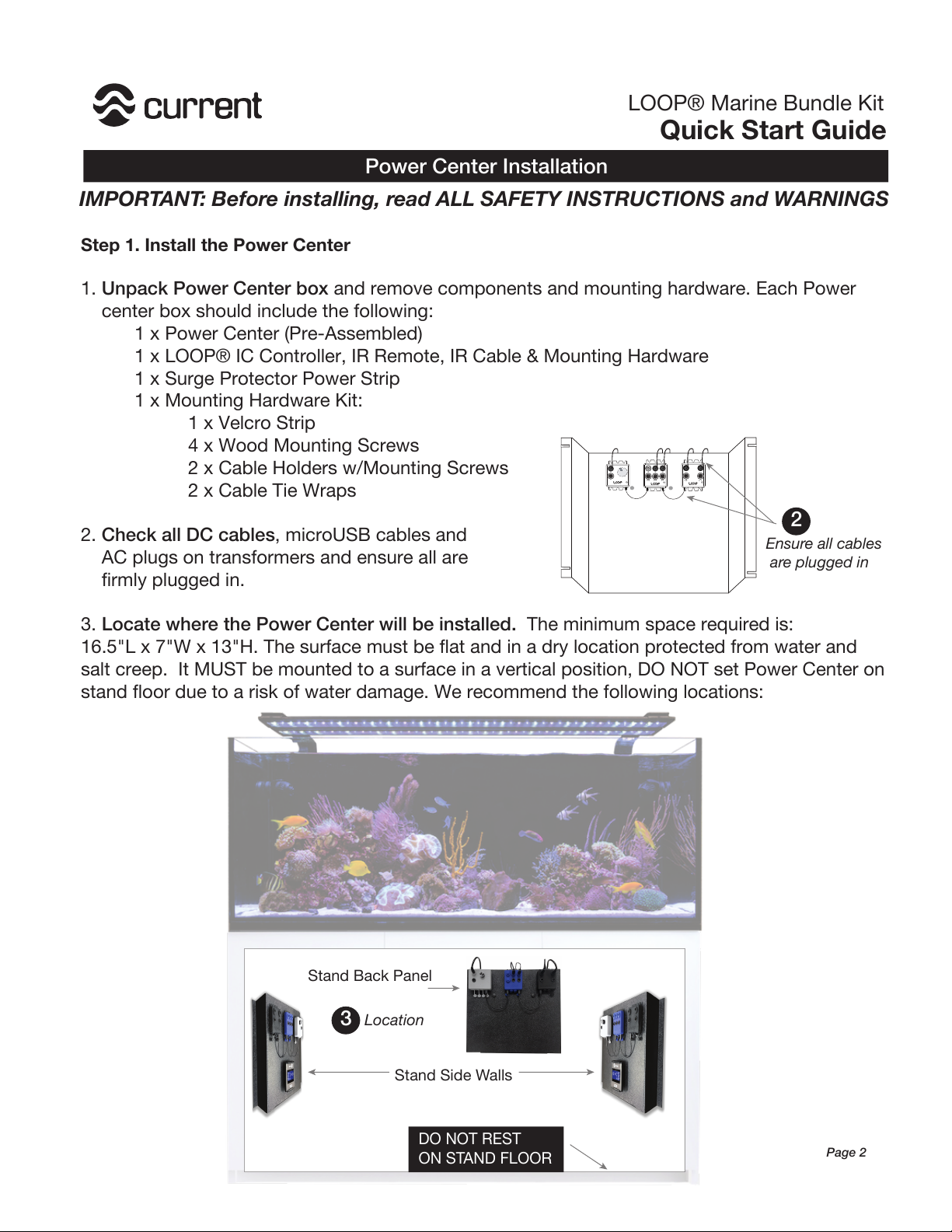
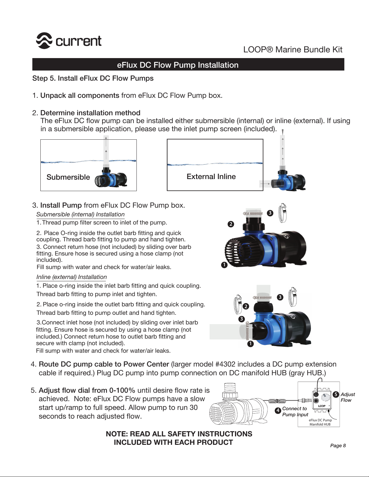
The eFlux DC flow pump can be installed either submersible (internal) or inline (external). If using
in a submersible application, please use the inlet pump screen (included).
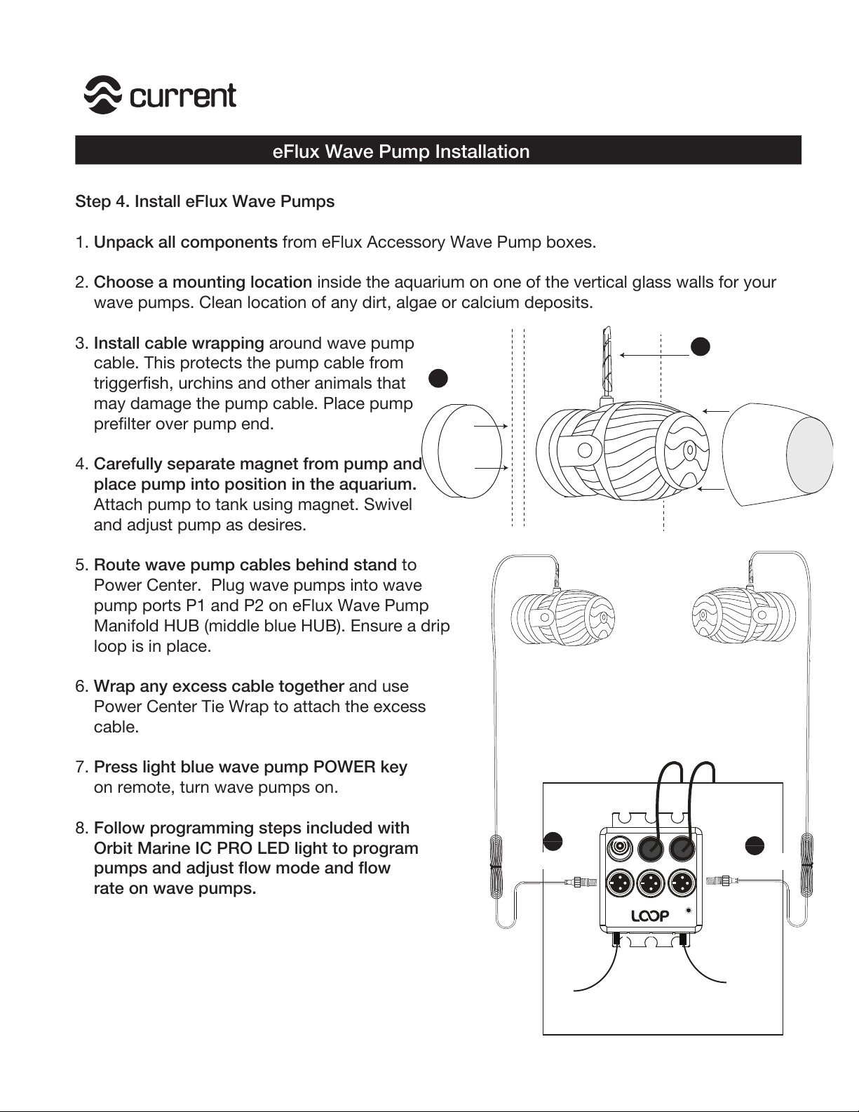
Submersible External Inline
3. Install Pump from eFlux DC Flow Pump box.
1
2
3
3
1. Thread pump filter screen to inlet of the pump.
2.
Place O-ring inside the outlet barb fitting and quick
coupling. Thread barb fitting to pump and hand tighten.
Submersible (internal) Installation
3. Connect return hose (not included) by sliding over barb
fitting. Ensure hose is secured using a hose clamp (not
included).
2. Place o-ring inside the outlet barb fitting and quick coupling.
Thread barb fitting to pump outlet and hand tighten.
Inline (external) Installation
3.Connect inlet hose (not included) by sliding over inlet barb
fitting. Ensure hose is secured by using a hose clamp (not
secure with clamp (not included).
1. Place o-ring inside the inlet barb fitting and quick coupling.
Thread barb fitting to pump inlet and tighten.
Fill sump with water and check for water/air leaks.
included.) Connect return hose to outlet barb fitting and
Fill sump with water and check for water/air leaks. 1
2
3
4. Route DC pump cable to Power Center (larger model #4302 includes a DC pump extension
cable if required.) Plug DC pump into pump connection on DC manifold HUB (gray HUB.)
5. Adjust flow dial from 0-100% until desire flow rate is
achieved. Note: eFlux DC Flow pumps have a slow
start up/ramp to full speed. Allow pump to run 30
seconds to reach adjusted flow. eFlux DC Pump
Manifold HUB
NOTE: READ ALL SAFETY INSTRUCTIONS
INCLUDED WITH EACH PRODUCT
Connect to
Pump Input
4
Adjust
Flow
5
Page 8

This manual suits for next models

2

Other Current Aquarium manuals

Current Satellite User manual

Current

Current Satellite User manual

Current 7058 User manual

Current

Current 7058 User manual

Current Satellite LED Plus Pro User manual

Current

Current Satellite LED Plus Pro User manual

Current SERENE 13G User manual

Current

Current SERENE 13G User manual

Current Aquabetta 7001 User manual

Current

Current Aquabetta 7001 User manual

Current AQUACHEF 8024 User manual

Current

Current AQUACHEF 8024 User manual

Current SERENE User manual

Current

Current SERENE User manual

Popular Aquarium manuals by other brands

prodac Magic Feeder manual

prodac

prodac Magic Feeder manual

TMC Reel Pulsar Connect LPS-6 instruction sheet

TMC

TMC Reel Pulsar Connect LPS-6 instruction sheet

icasa LEDP20 user manual

icasa

icasa LEDP20 user manual

TMC aquaGro CO2 Compact Diffusers manual

TMC

TMC aquaGro CO2 Compact Diffusers manual

Dupla 80210 user manual

Dupla

Dupla 80210 user manual

Jellyfish Art Jelly Cylinder Nano Guide to Success

Jellyfish Art

Jellyfish Art Jelly Cylinder Nano Guide to Success

EHEIM Autofeeder+ operating manual

EHEIM

EHEIM Autofeeder+ operating manual

Dupla MARIN Ocean Lux LED Controller instructions

Dupla MARIN

Dupla MARIN Ocean Lux LED Controller instructions

CIANO Nexus Pure 25 user guide

CIANO

CIANO Nexus Pure 25 user guide

Dennerle Nano corner filter XXL instructions

Dennerle

Dennerle Nano corner filter XXL instructions

Dennerle Scaper's Flow operating instructions

Dennerle

Dennerle Scaper's Flow operating instructions

JBL 6143100 quick start guide

JBL

JBL 6143100 quick start guide

Oase BioCompact 25 Operating instructions and guarantee

Oase

Oase BioCompact 25 Operating instructions and guarantee

Oase HeatControl Operating instructions and guarantee

Oase

Oase HeatControl Operating instructions and guarantee

Aqueon ProMag instructions

Aqueon

Aqueon ProMag instructions

Deltec TC 1000ix operating instructions

Deltec

Deltec TC 1000ix operating instructions

Marineland Eclipse Three Quick setup guide

Marineland

Marineland Eclipse Three Quick setup guide

Cobalt Aquatics E-X-T 26000 Instructions and warranty

Cobalt Aquatics

Cobalt Aquatics E-X-T 26000 Instructions and warranty

manuals.online logo
manuals.online logoBrands
  • About & Mission
  • Contact us
  • Privacy Policy
  • Terms and Conditions

Copyright 2025 Manuals.Online. All Rights Reserved.