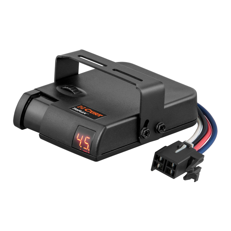
curt DISCOVERY 51126 User manual

INSTALLATION MANUAL 51126
DISCOVERY™NEXT BRAKE CONTROLLER

CURTMFG.COM •PRODUCT SUPPORT: 877.287.8634 •51126-INS-RA •PAGE 2
1. Main module with CURT quickplug
2. Mounting Bracket
3. Mounting Screws
4. Base plate adhesive pad
5. Cable ties
1. Drill
2. Drill bit, 1/8"
3. Phillips screwdriver
4. Pry tool
CONTROLS & COMPONENTS TOOLS LIST
2
3
4
5
1
TABLE OF CONTENTS
Controls & Components
Tools List
Before You Begin
Controls
Wiring
Wiring the Controller
Wiring Diagram
Mounting the Brake Controller
Modes & Indicators on the LED Display
Initial Setup
Test Drive & Adjustment
Bench Test
Troubleshooting Guide
page 2
page 2
page 3
page 3
page 4
page 4
page 5
page 6
page 7
page 11
page 12
page 12
page 14

PAGE 3 •51126-INS-RA •PRODUCT SUPPORT: 877.287.8634 •CURTMFG.COM
IMPORTANT: Read and follow installation manual carefully.
Failure to do so could result in damage to the brake control unit,
loss of trailer brakes or poor brake performance.
Disconnect the electrical plug between the trailer and tow vehicle
before testing a breakaway switch. Failure to disconnect may
damage the brake control unit. Avoid mounting the brake control
module near a CB radio or other RF transmitter.
The main module's positive (with 30-amp circuit breaker)
and ground wires must be connected directly to the tow vehicle's battery
using a minimum of 10-gauge stranded wire. Connecting to existing
wiring or an alternate ground may damage the vehicle's circuits, lead to
failure of the brake control module, loss of trailer brakes or vehicle fire.
Note: Removal of the factory quick plug can void the warranty.
• Brake control harness, supplied with the tow vehicle (if equipped)
• CURT quick plug harness - custom connector for specific vehicles
(see the CURT catalog for availability)
• CURT #51515 / #51516 - quick plug with pigtails
• CURT #51500 - universal brake control wiring kit
One or more of the following may be needed to complete the installation:
BEFORE YOU BEGIN
NOTICE
If product is to be installed in a vehicle with factory-equipped
brake controller or (ITBC) integrated trailer brake control, see the
vehicle owners manual for any necessary instructions for install.
CONTROLS
1. Display
2. Load adjustment
3. Gain adjustment
4. Manual Override
4
23 1

CURTMFG.COM •PRODUCT SUPPORT: 877.287.8634 •51126-INS-RA •PAGE 4
WIRING THE CONTROLLER
1. Determine the harness style needed (CURT custom vehicle
harness or CURT universal splice-in pigtail harness)
Note: Removal of factory-equipped brake controls may require
a dealer to service the harness in order to function. Splice-in harnesses
may void warranty. Check owners manual for harness information.
2. Locate the vehicle plug and remove any anti-rattle foam. Remove
the dust cover and connect the CURT custom wiring harness. Route
the harness into the dash area, making sure the harness is out of
the way of any moving parts. Secure with the provided cable ties.
3. Check to see that your foot controls are un-obstructed by the harness.
4. Plug the harness into the brake controller.
Note: Some controllers will start right away and others need to have
the vehicle in the run position or running to power the brake controller.
WIRING
Disconnect the tow vehicle's negative battery terminal from its battery
post before beginning the installation process. Most trucks and utility
vehicles are equipped with a plug from the factory that allows quick
brake control installation. Check the vehicle owner's manual for plug
availability, location and installation. If the mating plug supplied with the
vehicle is no longer available, a CURT quick plug can be used. See the
CURT catalog for application information. For tow vehicles not equipped
with a factory brake control plug, we suggest purchasing the CURT
universal brake control wiring kit #51500.
Mount the 30-amp, auto-reset circuit breaker
as close to the battery as possible.
IMPORTANT: When passing wires through sheet metal, always
go through an existing grommet. If there is no grommet, install one
or use silicone sealant to protect the wires from sharp edges.
Insert two 10-gauge wires, one white and one black, from the mounted
brake control to the battery area. Using a ring terminal, connect the black
wire to the 'AUX' side of the 30-amp circuit breaker. Leave the white wire
to be connected later. Using a 10/12-gauge butt connector, attach the
black wire from the 'AUX' side of the 30-amp circuit breaker to the brake
control's black wire. Again using a 10/12-gauge butt connector, attach
the white wire from the battery area to the brake control's white wire.
Run a 10-gauge blue wire from the tow vehicle's trailer plug 'BRAKE'
terminal to the brake control. Using a 10/12-guage butt connector,
connect this wire to the brake control's blue wire.

PAGE 5 •51126-INS-RA •PRODUCT SUPPORT: 877.287.8634 •CURTMFG.COM
WIRING DIAGRAM

CURTMFG.COM •PRODUCT SUPPORT: 877.287.8634 •51126-INS-RA •PAGE 6
1. Mount the unit securely to a solid surface where it is easily accessible to
the driver. The area behind the mounting location must be clear to prevent
damage to vehicle if using screws. The angle at which it's mounted will
not effect the operation or calibration of this controller (Fig 1).
2. Hold the mounting bracket in the position selected and mark the hole
locations of the bracket on the mounting surface. Check that the mounting
screws will not interfere with anything on the back side of the dash.
3. Peel off one of the release liners of the double-sided
adhesive pad and stick onto the brake controller mount.
4. (Optional - screw installation) Using a 1/8" diameter bit,
drill holes in the double-sided adhesive pad so you
can see the marked locations on the dash.
5. Remove the second release liner holding the
mount slightly back from the mounting surface
and then firmly press the mount to the dash.
6. (Optional - screw installation) With a Phillips head screwdriver,
start installing the screws to verify location of the holes.
Tighten the screws to secure the bracket, being careful
not to strip the holes by over-tightening.
7. Slide the controller onto the mount until it locks into place.
You will hear a clicking noise if it is correctly installed. (Fig 2)
MOUNTING THE BRAKE CONTROLLER
Figure 1
Figure 2

PAGE 7 •51126-INS-RA •PRODUCT SUPPORT: 877.287.8634 •CURTMFG.COM
MODES & INDICATORS ON THE LED DISPLAY
The LED display shows the output setting when the control is activated. It
is used to set up and monitor the brake controller and can be used when
troubleshooting. There are six modes of operation and eight indicator
sequences (shown below). See pages 8 through 11 for more information.
Press the control button to switch between modes.
MODES
INDICATORS
Load Sensitivity - trailer
brake aggressiveness
Manual - manual
override output is active
Calibration Overloaded Low Voltage Electrical
Short
Disconnected Connected Not Connected Reconnect
Auto - output at brake
pedal is active
Gain - output to
trailer / gain adjustment
Brightness -
Adjust screen brightness
Day Mode Night Mode

CURTMFG.COM •PRODUCT SUPPORT: 877.287.8634 •51126-INS-RA •PAGE 8
• The LED screen will show an output proportional to the
brake output on a scale from 1 to 9.9, based on how hard
you are pressing the manual control pinch trigger (#4)
Manual
Brightness
MANUAL CONTROL (PINCH TRIGGER - RIGHT SIDE OF DISPLAY)BRIGHTNESS CONTROL
Manual brake control activation is used in situations where a
slow reduction in speed is desirable. As the manual control is
pushed, the brake controller begins to apply the trailer brakes.
The manual control is set up to allow limited power to the output control,
depending on the setup of the brake controller (pages 11 through 13).
The output will be shown on the display when the manual control is
actuated. Brake light activation with the manual control is also intended
to come on. Some tow vehicle circuits do not allow power for brake lights
from a second source. In these applications, the CURT custom wiring
harness has provision to prevent this. The brake light connection
(red wire) is still required to activate the brake control.
Adjust brightness by long pressing the upper gain
rocker switch (#3) then use the load adjustment rocker
switch (#2) to increase or decrease the brightness.
Day Mode
Night Mode
DAY / NIGHT MODE
• Press the orange mode button (#3) to scroll through
controller options until you reach day / night mode.
- To set to day mode, press
the black 'down' arrow button
- To set to night mode, press
the black 'up' arrow button

PAGE 9 •51126-INS-RA •PRODUCT SUPPORT: 877.287.8634 •CURTMFG.COM
• The gain adjustment is the orange rocker
switch (#3) on the left of the controller
• Adjusting the gain
- Upper rocker switch increases
power level to the brakes
- Lower rocker switch decreases
power level to the brakes
• After 10 seconds of no user input,
the interface will switch to sleep mode
and the display will go to sleep
Gain
GAIN CONTROL (LEFT SIDE OF DISPLAY - FARTHEST LEFT)
The gain control establishes the maximum amount of power
available to the trailer brakes when braking. The only exception
would be when the manual control is set up for 100% braking.
The gain control can be adjusted during initial setup
or anytime when trailer load changes and adjustment
is needed for changing road or driving conditions.
• Shows output power from 0.5 to 9.9 when
the vehicles brakes are being applied
• After gain and load have been adjusted, this will
show the amount of power to the trailer over time
- The gain is an amount of power to the
trailer based on the operator's settings
- The load is the amount of time needed to stop
the trailer based on the operator's settings
• The control adjustment is the black rocker
switch just to the left of the display (#2)
- Upper rocker switch increases brake aggressiveness
- Lower rocker switch decreases brake aggressiveness
• 1 to 9 scale
Auto - output
power over
time as brakes
are applied
Load Sensitivity
- trailer brake
aggressiveness
AUTO (SHOWS OUTPUT FROM CONTROL TO TRAILER BRAKES)
LOAD CONTROL (LEFT SIDE OF DISPLAY - RIGHT SWITCH)
The load control adjusts the trailer brake aggressiveness.
Load adjustment has no effect on the manual control.
The load control can be adjusted for individual driver
preference, trailer load changes or changing road conditions.

CURTMFG.COM •PRODUCT SUPPORT: 877.287.8634 •51126-INS-RA •PAGE 10
• Indicates when the brake controller
is in start up mode or restart mode.
• Occurs when power is applied to the brake
controller. Some vehicles have power to the
controller at all times and others only after
the vehicle is in running position or is running
• Indicates when a trailer
has been connected
• Indicates when the controller has recognized
a trailer connection. This happen when brakes
are applied and no trailer is connected
Brake controller
start up
Connected
Not connected
START UP INDICATOR
CONNECTED INDICATOR
NO TRAILER CONNECTION INDICATOR
• Indicates when the brake controller is in
an overload or short-circuit condition
• The screen shows brake overload or short condition
- The trailer brake wire is grounded to the
trailer and service needs to be completed
• Indicates when the stop lamp is in an
overload or short-circuit condition
• The screen shows brake overload or short condition
- The stop lamp wire is grounded to the trailer or the
bulb is burnt out and service needs to be completed
• Indicates a low battery voltage condition
• The screen shows low battery voltage condition
- The brake controller is not receiving enough
voltage to provide the trailer with the needed
voltage at the settings the controller is at.
Service needs to be completed
Overloaded
Electrical Short
Low Voltage
OVERLOAD INDICATORS

PA GE 11 •51126-INS-RA •PRODUCT SUPPORT: 877.287.8634 •CURTMFG.COM
• Indicates when the trailer has been disconnected
(flashing) or if the brakes are pressed with no trailer
connected (icon is on as long as brake pedal is pushed)
• Indicates when the trailer needs to be disconnected
and reconnected to function correctly
Disconnected
alert
Reconnect
notice
DISCONNECTED INDICATOR
RECONNECT INDICATOR
INITIAL SETUP
Once all electrical connections are complete inside the vehicle, plug the
trailer electrical connector into the tow vehicle plug. The brake controller
will sense the trailer upon connecting to the trailer after 10-15 seconds.
Upon connecting to the trailer and applying the brakes, the brake
controller will sense the trailer immediately. Every time the vehicle starts,
power is applied to the brake controller and it will restart, displaying the
start up icon on the display. Once the display becomes blank / black,
the display will remain blank / black until the manual control is applied,
the orange adjustment rocker switches are pressed or the vehicle brake
pedal is applied. To recalibrate the brake controller, restart the vehicle
or disconnect the controller from the vehicle. The brake controller
will retain the last settings applied upon restarting.
Make any preliminary gain and load adjustments with the trailer connected
and engine running to ensure proper charge voltage. Adjust the output /
gain by pressing the orange rocker switches to the left of the display to
the range desired. Adjust the controller's brake load by pressing the right
rocker switch until the brake control is in the desired range.

CURTMFG.COM •PRODUCT SUPPORT: 877.287.8634 •51126-INS-RA •PAGE 12
BENCH TEST
Note: If a quick plug pigtail is not available, push pins
can be used to make a direct connection to the female
terminals of the Discovery™quick plug housing.
Ensure that the brake control wires, quick plug wires,
push pins and test leads do not make contact with each other or any
other metal surface. Failure to do so may damage the brake controller.
Connect the module to the quick plug to provide accessible wires for
bench testing. Connect the white ground wire of the main module and
the ground wire of the bulb to the negative terminal of the 12V battery.
Leave the red brake input wire and blue output wire disconnected.
Connect the black battery wire of the module to the positive
terminal of the 12V battery. If the brake controller is wired properly
and the Discovery™is operational, the display will power on.
Parts Needed:
Brake Control Setup
1. Standard 1156 automotive bulb in a socket
2. Charged 12V battery
3. Alligator clip test leads OR wire and wire nuts
4. CURT #51515 / #51516 quick plug with pigtails OR push pins
TEST DRIVE & ADJUSTMENT
Both the gain and load can be adjusted to achieve smooth, firm stops.
Gain and load adjustments should only be made while stopped, with the
transmission in park or neutral, parking brake applied, foot off the brake
pedal and no manual override actuation. Gain and load settings will be
visible for five seconds after the adjustments are made and will then go
into sleep mode (blank / black screen). Beginning with the gain adjustment,
locate a vacant street or parking area and drive forward on a dry and level
paved or concrete surface. At approximately 25 mph, apply the vehicle
brakes. The brakes should slow the vehicle but not stop it. If the stopping
power is insufficient, increase the gain control by pressing the upper left
(orange) rocker switch. If the trailer brakes lock up, adjust the output
control by pressing the lower left (orange) rocker switch to decrease gain.
Repeat this process until stops are firm, just short of trailer tire lock up.
Once the gain is set, adjust the load by using the same process for setting
the gain. If the stop seems slow and more aggressive braking is desired,
increase the load level by pressing the upper right (black) rocker switch.
If the stop seems too aggressive, decrease the load level by pressing the
lower left (black) rocker switch. Make several stops at various speeds and
adjust the load until stops are smooth and firm. Adjustment to the gain may
also be needed as the load adjustments are being made or terrain changes.
This process should be repeated for any weather,
weight or loading changes to the items in / on the vehicle or trailer.
Note: If any problems occur during setup, refer to the
'Troubleshooting Guide' on the last two pages of this manual.

PAGE 13 •51126-INS-RA •PRODUCT SUPPORT: 877.287.8634 •CURTMFG.COM
Adjust the output setting to its maximum setting of 10.
Adjust the sensitivity settings to its most aggressive setting
of 9. Activate the manual control up to its full output. While
actuating the manual control, the brightness of the bulb will
correspond with the output shown by the brake control.
Release the manual control to deactivate and turn off the light.
Manual Control Testing
Ensure the Discovery™blue trailer brake signal wire is connected
to the bulb. Once the CURT start up screen disappears or turns
black, the control module is ready. Pressing the manual control
lever will activate the controller to display and will ramp-up according
to the pressure applied to the manual control level. This will also
turn on the light in accordance to the amount of pressure applied
to the manual lever. This visually shows power to the trailer
brakes and you can proceed to test the manual control.
The Discovery™is a time-based brake controller so as the brake pedal
is pushed, the controller ramps up to full power over time according
to the gain and load setting of the controller. This can also be tested
by attaching the red wire to the positive side of the 12v battery.
IMPORTANT: Read and follow all
warnings and cautions shown on the battery.
RED: BRAKE SIGNAL
Connect red wire when
simulating an auto brake
(vehicle brake pedal
activates the control) BLUE: BRAKE OUTPUT
Connect after the unit is powered.
Reconnect if required during recalibration.
Standard 1156 automotive
bulb in lamp socket.
BLACK: BATTERY
#51515 / #51516:
QUICK PLUG
WHITE: GROUND

CURTMFG.COM •PRODUCT SUPPORT: 877.287.8634 •51126-INS-RA •PAGE 14
TROUBLESHOOTING GUIDE - NO TRAILER CONNECTED
Condition Display Problem Cause Possible Solution
Display does not light up when brake
pedal or manual control is used
No power to controller, no ground,
reveresed black and white wires
or circut breaker blown
Check and repair connections
(see 'Wiring' section)
Display shows 'Not Connected' Red wire connected to the wrong side of
the stoplight switch or to the incorrect wire
Check and repair connections
(see 'Wiring' section)
Display shows 'Low Volt'
- Can occur with the trailer connected
Tow vehicle's system voltage is low Check tow vehicle's battery and charging station
Display shows 'Short'
- When manual control is applied
Red wire connected to ground side of
stoplight switch or is shorted to ground
Check brake control wiring, may require change
to switch setting (see 'Manual Control' section)
Display shows 'Overload'
- When the brake pedal or
manual override is used
Short in the blue wire output
circut or trailer plug
Locate and correct short
Display shows nothing when battery power
has been connected for a period of time
and the engine is not being cranked
Inadequate battery or ground
wiring to the brake controller
Check brake controller wiring

PAGE 15 •51126-INS-RA •PRODUCT SUPPORT: 877.287.8634 •CURTMFG.COM
Condition Display Problem Cause Possible Solution
Display shows 'not connected' when power is
applied to controller. No trailer brakes when
brake pedal or manual control is used
No connection between brake controller
and trailer brakes – blue wire circuit
Confirm connection to trailer connected
Confirm connector terminal positions
Check trailer
No trailer brakes, pedal or manual Short or overload in trailer brakes Troubleshoot trailer brake circuit according
to the brake manufacturer's instructions
Trailer brakes work but error shows Miswired trailer, wiring shorted or bulb out Check bulbs
Check for possible shorts
No trailer brakes, pedal or manual Short to trailer brakes in
wiring or brake assembly
Check for shorts in wiring and in each electric
brake. You may see or hear the wiring sparking
No trailer brakes, pedal or manual Electrical connection failed Check connector for fit and blockages
No trailer brakes, pedal or manual Loss of trailer connection,
unplugged or bad wiring
Stop and check trailer connector
TROUBLESHOOTING GUIDE - WITH TRAILER CONNECTED

WARRANTY & PRODUCT REGISTRATION
CURT stands behind our products with industry-leading
warranties. To get copies of the product warranties,
register your purchase or provide feedback, visit:
curtmfg.com/registration
Connect with us
Table of contents
Other curt Controllers manuals
Popular Controllers manuals by other brands

Hubbell
Hubbell Electric Fire Pump Controllers LXi 1300 Specifications

Ruijie
Ruijie RG-WS6512 Installation and reference guide

Hypertherm
Hypertherm Powermax45 228262 Field Service Bulletin

4qd
4qd PRO-160 Series instruction manual

E-T-A
E-T-A E-1071-623 manual

Johnson Controls
Johnson Controls MR4PMUHV manual