Curtis JOHN DEERE 4500 Operating instructions

p/n: IM-1JD4120
INSTALLATION & OWNER’S MANUAL
The contents of this envelope are the property of the owner.
Be sure to leave with the owner when installation is complete.
CAB INSTALLATION INSTRUCTIONS
JOHN DEERE 4000 SERIES (4500/4600/4700)
(4510/4610/4710) (4120/4320/4520/4720)
HARD SIDED CAB ENCLOSURE (p/n: 1JD4120AS)
SOFT SIDED CAB ENCLOSURE (p/n: 1JD4120SS)
This Curtis Cab is designed and
manufactured for use only as reasonable
weather protection. This cab is not appli-
cable, Nor should the cab be considered as protection against
roll over, collision or other accidents that may result. This cab is
NOTaR.O.P.S.cab. Extreme care should be taken when operat-
ing and by qualified, experienced operators only.
ExposuretoCarbonMonoxidecanCause
illness,seriousinjuryordeath.Never
operate vehicle if suspicious of Carbon
Monoxide. Inspect exhaust system for leaks monthly. Leaks can
result from loose connections, corrosion, cracks or other damage
to the exhaust manifold. If leaks are found, repair or replace
exhaust system. Do not use vehicle until repair or replacement is
complete.
CABS/BLADES/ SPREADERS/ACCESSORIES
driver and passenger.
exceed the vehicles rated capacity including
from the vehicles rated capacity and never
brochures. Deduct the accessories total weight
Curtis accessory weights are listed in product
add additional weight to the base vehicle. All
Curtis Cabs, blades and general accessories
ADDED
WEIGHT
Note: 4510 shown with soft sided
cab and optional work lights and
optional strobe light.
Rev. T, p. 1 of 11

DESIGN CONCEPT
Curtis Cabs feature an assembly of parts designed for your vehicle which require
adjustment and alignment of components to accommodate vehicle variations and
provide proper weather protection. For accurate installation, proper operation, and
years of satisfaction, please read and understand the installation instructions.
From all of us at Curtis, we thank you for choosing our product.
CAB INSTALLATION
BEFORE YOU START
HELPFUL REMINDERS:
A. Leave all bolts loose for later adjustment unless otherwise specified.
B. Read and understand all instructions before beginning.
C. Plastic washers have been supplied to provide a weather seal around
all exterior fasteners. The plastic washer should be installed under each
bolt head directly against the outside cab surface. Care should be taken
not to over tighten the fasteners and damage the plastic washer.
Also use metal washers as required.
D. Apply a clear silicone sealant to seal any minor gaps that may occur due
to vehicle variances. For example, windshield cowl to unitized frames.
TOOLS REQUIRED:
This Curtis Cab is designed and manu-
factured for use only as reasonable
weather protection. This cab is not applicable, nor should
the cab be considered as protection against roll over,
collision or other accidents that may result. This cabs is
NOTaR.O.P.S.cab. Extreme care should be taken when
operating and by qualified, experienced operators only.
ExposuretoCarbonMonoxidecan
Causeillness,seriousinjuryordeath.
Never operate vehicle if suspicious of Carbon Monoxide.
Inspect exhaust system for leaks monthly. Leaks can result
from loose connections, corrosion, cracks or other damage
to the exhaust manifold. If leaks are found, repair or replace
exhaust system. Do not use vehicle until repair or replace-
ment is complete.
driver and passenger.
exceed the vehicles rated capacity including
from the vehicles rated capacity and never
brochures. Deduct the accessories total weight
Curtis accessory weights are listed in product
add additional weight to the base vehicle. All
Curtis Cabs, blades and general accessories
ADDED
WEIGHT
7/16”, 1/2”, 7/8”, and 1”
OPEN END WRENCHES
7/16 IN.
3/8 DRIVE
SOCKET
1/2 IN.
3/8 DRIVE
DEEP
SOCKET
3/8” DRIVE
RATCHET
NO. 2 MEDIUM
PHILLIPS HEAD
SCREWDRIVER
3/8 IN.
ELECTRIC
HAND DRILL
3/8 IN.
DRILL BIT
3/16 INCH
ALLEN
DRIVE
3/8 DRIVE
10MM
3/8 DRIVE
SOCKET
p. 2 of 11

p. 3 of 11
1. VEHICLE PREP.
1.1 Remove both grab handles (one per side) (see fig. 1.1).
1.2 Remove, and discard the outer bolt and nut in each floorboard (see fig. 1.1).
1.3 Remove, and save two (2) plastic pins (per side) holding the floor mat down
(see fig. 1.1).
1.4 Tip driver’s seat forward.
1.5 Drill an oversized hole (3/8” dia.) thru plastic located behind seat and
shown in fig. 1.5. The drilled hole is to be exactly over the center of the
left weld nut. Transfer the hole location from the bottom up. (Note: take pre
cautions to avoid damaging the metric threads in the nuts welded below.)
( Suggestion: wedge plastic up in the air with a small piece of wood to keep
drill bit away from weld nut threads.) This hole will be used to fasten the rear
panel assembly in place (ref.: see fig. 2.3.1).
2. REAR PANELASSEMBLY
2.1 Pre-assemble lower rear panel, rear legs, and rear window support using a
total of eight (8) button head screws. (Note: the soft side version does not
have a rear window support). See fig. 2.1 for the all steel pre-assembly. To
attach the rear window support, use four 5/16” button head screws, steel
washers, and nylon washers. To attach the lower rear panel, use four 5/16”
button head screws, steel washers, nylon washers, and locknuts.
2.2 Install two (2) pieces of 1” round bulb rubber (28” long) on three (3) edges
per side as shown in fig. 2.1.
2.3 With assistance, and from the side of the tractor, place the pre-assembled unit
behind the seat and in between the roll bar uprights (see fig. 2.3). (Make sure
the rubber seal that will rest on top of the fenders is facing outwards.) Secure
the bottom of the rear panel (thru the newly drilled hole) to the left metric
weld nut already in place. (See fig. 2.3.1) Use a 6mm x 1.0 x 20mm long hex.
head bolt and 6mm flat washer from the hardware kit.
2.4 Secure the lower rear panel to the roll bar using the existing roll bar bolts as
shown in fig. 2.4. Attach the rear panel mounts to the rear panel with the
locknuts being on the inside of the cab. Use two button head screws, plastic
washers, steel washers, and locknuts.
Fig. 1.5 Drill holes in plastic
CABS/BLADES/ SPREADERS/ACCESSORIES
Fig. 1.1 Remove grab handle,
bolt, and two plastic pins/side
plastic pins bolt
drill
Fig. 2.3 Install
Rear Panel
Assembly
Fig. 2.4
Rear Panel
Mount
roll bar bolt
Fig. 2.1
Pre-assemble
Rear Panel
Fig. 2.3.1
Secure
Rear Panel
metric bolt
not on
S.S. cabs
1” round bulb

p. 4 of 11
CABS/BLADES/ SPREADERS/ACCESSORIES
3. FRONT COWL
3.1 For the 10 Series models
(ref.: 4510, 4610, and 4710):
Pre-assemble the cowl and the cowl insert using a total of four bolts (5/16-18
x 3/4” long), eight steel washers, four nylon washers, and four locknuts.
Note: fig. 3.1 shows the cowl insert and which four holes to bolt up initially
(bolt location “A”). Bolt the cowl insert to the inside surface of the cowl.
Note: the cowl insert and the associated hardware is only required on the 10
Series model numbers listed above.
3.2 Next, bolt the front legs onto the inside surface of the cowl insert so that the
cowl insert becomes sandwiched between the cowl and the front legs (bolt
location “B”). Attach the front legs using a total of two bolts (5/16-18 x 3/4”
long), four steel washers, two nylon washers, and two locknuts. Install 1”
bulb rubber (approximately 80”) along the sheet metal edges as shown in
reference fig. 3.2. Trim any extra bulb rubber.
3.3 For the 20 Series models
(ref.: 4120, 4320, 4520, and 4720):
Pre-assemble the cowl and front legs (as shown in fig. 3.2) by fastening to-
gether at the inside hole only, using two 5/16” x 3/4” long button head
screws, steel washers, nylon washers, and locknuts. Locknuts to be on the
inside surface of the cowl assembly. Install 1” bulb rubber (approximately
80”) along the sheet metal edges as shown in fig. 3.2. Trim any extra bulb
rubber. Note: the cowl insert (shown in fig. 3.1) and the associated hardware
is NOT required on the 20 Series model numbers listed above.
Fig. 3.2
20 Series front cowl assembly
(outside surface shown)
1” bulb rubber
bolt these
two places
only
cowl
front legs
Fig. 3.1
10 Series
front cowl insert
A
A A
B B
A

p. 5 of 11
CABS/BLADES/ SPREADERS/ACCESSORIES
3. FRONT COWL(cont’d.)
3.4 For all models, place the cowl assembly onto the tractor with the flap of
bulb rubber extended inward towards the passenger’s compartment as shown
in fig. 3.4.
4. SIDE FRAMES
4.1 Remove doors from side frames (for easier handling) by unlatching and slid-
ing up and off the hinge pins..
4.2 Install left and right side frames to vehicle as shown in fig. 4.2. The bottom
of the side frame is to be on top of the tractor floorboard, but under the rub-
ber mat and under the bottom, bent flange of the front cowl assembly. Fasten
to front cowl assembly and rear legs using 5/16 x 3/4” long button head
screws, steel washers, and nylon washers. Push the side frame back and in-
stall a new, longer floorboard bolt (3/8 x 1 1/2” long carriage bolt), washer,
and locknut. The bolt is to pass through the bottom of the side frame and the
floorboard.
5. FRONT WINDSHIELD SUPPORT
5.1 Install the front windshield support to the side frames with the bent flange
down. Install only the bottom two 5/16 x 3/4” long button head screws, steel
washers, nylon washers, and locknuts. (see fig. 5.1) (Note: the top holes will
get fasteners once the roof is installed.)
6. WINDSHIELD
6.1 With assistance, install the windshield to the windshield support (see fig.
6.1). Use four 5/16 x 1 3/4” long flat head screws and 3/4” thick plastic
spacer blocks (placed between the plastic hinge and the windshield support
as shown in fig. 6.1.1). Do not tighten.
6.2 To install windshield bottom latches into the cowl brackets, open windshield
slightly. Grasp and squeeze the spring-loaded tabs and cradle latches into
cowl brackets, aligning tab bosses with their respective mounting holes.
3/4” thick spacer
Fig. 6.1.1 Spacer BlockFig. 6.1 Install WindshieldFig. 5.1 Windshield Support
only these two holes
Fig. 4.2
Side-
frame
Fig. 3.4 front cowl
installed (20 series shown)
bulb rubber inwards

p. 6 of 11
CABS/BLADES/ SPREADERS/ACCESSORIES
6. WINDSHIELD (continued)
6.3 To close, grasp the windshield bottom edge and lift slightly while pushing
closed. Fully close latches. Align sides of windshield with side frames and
tighten hinges. HINGES ARE PLASTIC COMPONENTS. DO NOT OVER
TIGHTEN. TORQUE TO 7 FT./LBS. MAX.
7. ROOF
7.1 With assistance, install roof as shown using 5/16 x 3/4” long button head
screws, plastic washers, steel washers, and locknuts in all holes except the
middle ones on the left and right side (these two bolts do not require lock
nuts). (see fig. 7.1). (Also note: front left, and front right corners take 1”
long bolts)
8. REAR WINDOW (hard side only)
8.1 Install two (2) ball studs to the inner curved surface of the window (Note:
the Philips head portion of the screw is to be on the outside of the window.)
The base of the ball stud goes against the inner surface of the window, with
the boss sitting inside the window hole. Bolt these components together,
making sure that the ball portion of the ball stud is facing the outside edge of
the window as shown in fig. 8.1.1 (so that the gas shocks will be as close to
the edge of the window as possible.)
threaded inserts here
Fig. 7.1 Install Roof
1” long bolt
CABS/BLADES/ SPREADERS/ACCESSORIES
Gas shock
Fig. 8.1.1 Ball stud
assembly view
Ball stud
Inside of window
Window will be in here
Fig. 8.1 Loose ball
stud components
Plastic countersunk
washer w/ built in o-ring
and a short flat head screw
Ball stud

p. 7 of 11
CABS/BLADES/ SPREADERS/ACCESSORIES
8. REAR WINDOW (continued)
8.2 Install rear window using same procedure as windshield. Once aligned and
tightened, open window and install gas springs to ball studs provided. Re-
lease latches from latch mounts and open window all the way in order to
snap the gas springs onto the ball studs. (see figures 8.2, 8.2.1, & 8.2.2).
Note: rear window has holes for optional wiper.
Note: rear window can be opened for ventilation, or latches can be com-
pletely released to access rear attachments.
9. FLOORBOARD (drill hole)
9.1 Line up the hole in the floorboard with the hole in the bottom, bent flange of
the front leg. Using these holes as a guide, drill thru the tractor floorboard
with a 3/8” drill bit as shown in fig. 9.1.
9.2 In this newly drilled hole, install a 5/16 x 3/4” long button head screw, steel
washers, and locknut.
9.2 Re-install the plastic pins to secure the floor mat.
10. DOORS
10.1 Install doors onto hinges. (see fig. 10.1) Work the doors back and forth
until
the hinges are completely seated. (NOTE: the hinges, inside latch, and
striker bolt can also be adjusted for proper engagement.)
10.2 On hard sided cabs install the gas springs to the frames and doors with
the small piston end towards the door. (See fig. 10.2) Press the button on the
compression fastener to lock the gas spring to the ball stud.
10.3 On soft sided cabs install the cable stops and hardware provided similar to
how the gas springs are installed (see 10.2). WARNING Do not attempt to
install gas springs on soft sided doors as this will damage to the doors!
10.4 Tighten all remaining bolts.
Rear Window
Fig. 8.2.2 Install Gas Springs
Gas Spring
Fig. 8.2 Install Rear Window
3/4” spacer
Fig. 8.2.1 Release latches
latches
Fig. 10.1 Install Doors
Fig. 9.1 Line up holes
drill here
Fig. 10.2 Gas
spring installation

p. 8 of 11
CABS/BLADES/ SPREADERS/ACCESSORIES
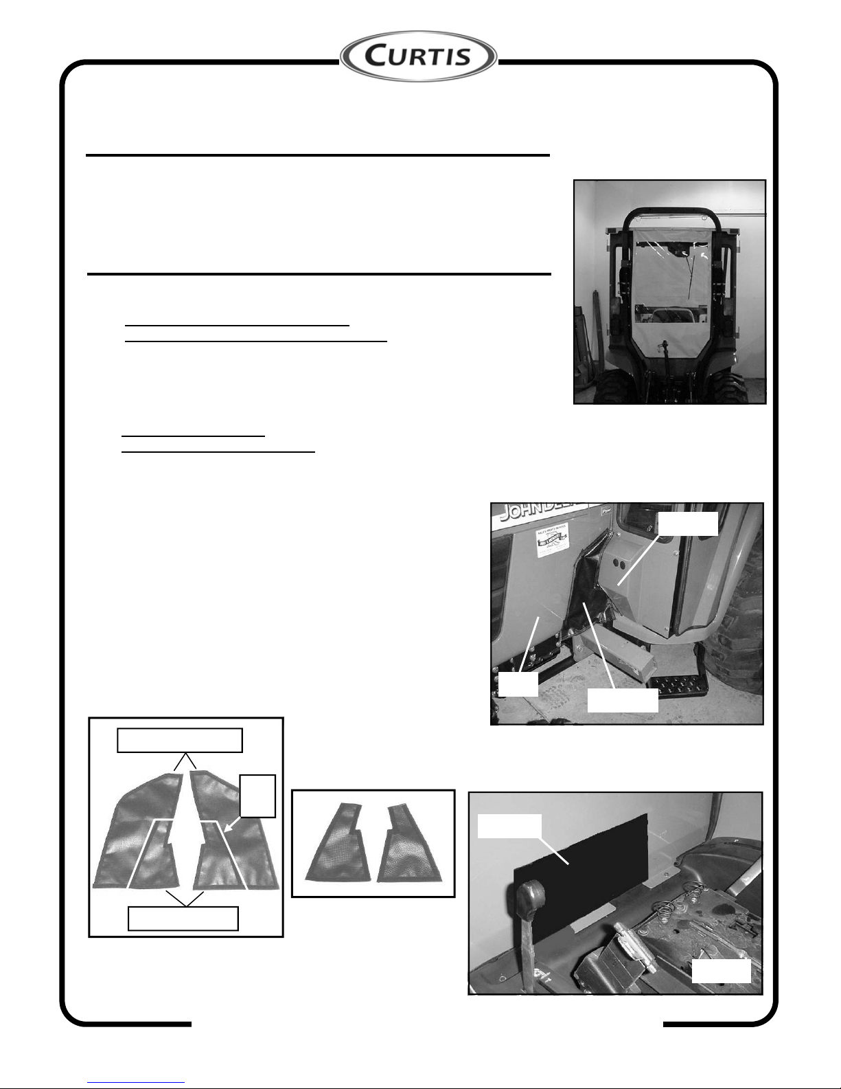
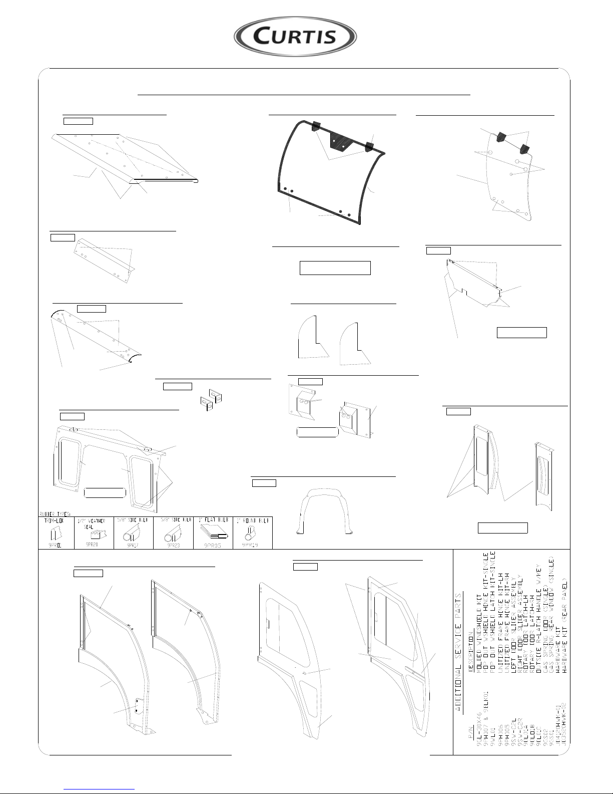
11. REAR CURTAIN (soft sided only)
11.1 Install rear curtain by snapping to the inside back vertical edge of the roof.
(see fig. 11.1)
11.2 (NOTE: adhesive backed velcro should be applied to a clean, dry surface at
room temperature.) Apply self adhesive hook velcro, as needed, along the
rear legs and rear panel. Adhere rear curtain to newly applied velcro strips.
12. FINISHING TOUCHES
12.1 Install wiper motor per instructions included with the wiper kit.
12.2 Install 5/16” plastic nut covers on all interior 5/16” locknuts.
12.3 For the 00 Series and 10 Series models
(ref.: 4500, 4600, 4700, 4510, 4610, and 4710):
Install vinyl front fillers by applying self adhesive hook velcro, as needed,
along the hood and front legs as shown in figure 12.3. (NOTE: adhesive
backed velcro should be applied to a clean, dry surface at room temperature.)
(NOTE: left, driver’s side shown, repeat for opposite side.) Install front vinyl
fillers to newly applied velcro strips.
12.4 For the 20 Series models
(ref.: 4120, 4320, 4520, and 4720):
Cut the vinyl front fillers as shown in fig. 12.4. Cut along the white
lines shown on the photo being sure to cut on the appropriate side
of the loop velcro. The photo shows the loop velcro side up. The
long cut to be made should follow along the edge of the 5/8” wide
loop velcro so the loop velcro remains fully intact on the small
piece of vinyl that is labeled “keep for 20 Series”. The shorter cut
to be made is approximately parallel to the bottom edge as shown
(finished product is shown in fig. 12.4.1). Apply self adhesive
hook velcro, as needed, along the hood and front legs. (NOTE:
adhesive backed velcro should be applied to a clean, dry surface
at room temperature.) Install the newly cut (saved) portion of the
front filler to the newly applied hook velcro on the vehicle (not
shown).
12.5 Install the rear filler as shown in fig. 12.5 in the same manner
as the front fillers. If your tractor is equipped with a backhoe,
cut the filler around the hydraulic lines using snips.
Fig. 11.1 Rear Curtain
Vinyl filler
Fig. 12.3
00 Series and 10 Series front filler installed
Hood
Front leg
Vinyl filler
Fig. 12.5
Rear filler
keep for 20 Series
discard for 20 Series
Fig. 12.4
20 Series front filler prep.
cut
lines
Fig. 12.4.1
20 Series front fillers
shown after being cut out
of larger 00 Series and 10
Series front fillers

p. 9 of 11
CABS/BLADES/ SPREADERS/ACCESSORIES
REV. A
Care and Maintenance Instructions
* Check and tighten hardware after 40 hours of operation.
Periodically inspect and tighten hardware for the remainder of the unit’s life.
* Wash the painted surfaces of the unit with commercial automotive cleaning
products.
* Clean windows with glass cleaner.
* Vinyl components should be washed with a mild solution of warm soapy water.
* Clear vinyl can be easily scratched. Be careful cleaning frost or snow from
windows. Do not roll curtains in cold weather. The windows become stiff and
may crack. Keep windows clean.
On 20 Series models, access Fuel Cap Filler as follows:
From inside of cab, open both pop-out windshield latches and disconnect latches at spring-loaded finger tabs.
Push windshield open far enough to fully open fuel cap filler cover.
Close windshield completely but do not reconnect spring-loaded finger tabs on latches at this time.
From outside of cab, fuel tractor being careful to prevent spillage.
When fueling is complete, open windshield far enough to close the fuel cap filler cover.
From inside of cab, reattach spring-loaded finger tabs.
IMPORTANT NOTICE

BALL STUD
*IN HOUSE APPLICATIONS
* HEATER
(INSIDE)
LABEL
BULB
* 1" ROUND * STRIKER
LH,RH
PLATES
* HINGE PIN
& HINGE
RIGHT
LEFT
CABS/BLADES/SPREADERS/ACCESSORIES p. 10 of 11
* 5/8" SIDE
BULB
RIGHT HANDLE
* OUTSIDE
HANDLE
* GRAB
LEFT
LATCH
* DOOR
QTY. P/N
REAR PANEL
PROCEDURE)
DECAL (STATING
1/2" WEATHER
SEAL (INSIDE)
JD4510AS-09L
JD4510AS-09R
J.D. 4000 SERIES HARD SIDED CAB PARTS LIST (p/n: 1JD4120AS)
3 SIDES
*
W/ 1/4" GRIP
1RIGHT
PER SIDE
7 PLACES
*INSERTS
5/16" - 18
UNITIZED SIDE
FRAMES HARD CAB
LEFT QTY.
1P/N
*3/8" HEYCO
PLUGS (2)
(1" FLAT BULB)
*
*FUEL FILL
WINDSHIELD LATCH
*
MOUNTS
*
WINDSHIELD
QTY. P/N
COWL
1/2" WEATHER
SEAL (INSIDE)
1 JD4120-08A
MOUNTS
*HEYCO PLUGS
(SERIAL #, OPTIONS,
DECALS (INSIDE)
& R.O.P.S.)
SEAL (INSIDE)
WINDSHIELD
SUPPORT QTY. P/N
1 JD4120-04
REAR WINDOW
QTY. P/N
SUPPORT 1 JD4510-05
1/2" WEATHER
*
HEADLINER
*
LOGO
TRIM-LOK *
QTY. P/N
ROOF
*REFLECTORS
1 JD4510-01
1/4" GRIP
RIGHT 1 JD4510-11R
SEAL (INSIDE)
1" ROUND BULB
JD4510AS-07R
JD4510AS-07L
BALL STUD
* HINGE SLEEVES
HARD DOORS LEFT
RIGHT
P/N
1
1
QTY.
* 1" HEYCO
PLUG
(ON SIDE SHOWN)
1/2" WEATHER SEAL
QTY. P/N
COWL INSERT 1 JD3520-17A
(1" FLAT BULB)
10 SERIES
*
& BALL STUDS
5/16" INSERTS
*
SEAL (OUTSIDE)
1 JD4120-15RRIGHT
1/2" WEATHER
1 JD4120-10L
1 JD4120-10R
QTY. P/N
FRONT LEGS
2 JD4510-12
*PLUGS
HEYCO *
LEFT
RIGHT
QTY. P/N
REAR LEGS
LEFT 1 JD4510-11L
1" ROUND BULB
1/2" WEATHER
SEAL (OUTSIDE)
*
QTY. P/N
FRONT
FILLERS 1 JD4120-15LLEFT
QTY. P/N
REAR FILLER
LATCHES
*
1 JD4510-16 *MOUNTS
1/2" WEATHER
WINDSHIELD LATCH
*
*1/2" WEATHER
SEAL (INSIDE)
QTY. P/N
1 JD4510-06A
LOWER
REAR PANEL
*LATCHES
*
*SIDE
BULB
5/8"
HINGES
QTY. P/N
WINDSHIELD
SEAM BULB
1 JD4510-02
*MOUNTS
SIDE
1/4" GRIP
BULB
(FACE OUT)
5/8"
*PLUGS
*
1 JD4510-03
QTY. P/N
SEAM BULB
GAS SHOCK
REAR WINDOW
*HINGES
YELLOW
GREEN
T-BLACK
GREEN
GREEN
GREEN
GREEN
GREEN
GREEN
T-BLACK
T-BLACK

LEFT
CABS/BLADES/SPREADERS/ACCESSORIES
*IN HOUSE APPLICATIONS
* STRIKER
LABEL
(INSIDE)
* HEATER
* 1" ROUND
BULB
PLATES
* HINGE PIN
& HINGE
LH,RH
RIGHT
LEFT
BULB W/
1/4" GRIP
* 5/8" SIDE
RIGHT
HANDLE
HANDLE
* OUTSIDE
* GRAB
p. 11 of 11
LATCH
* DOOR
1/4" GRIP
3 SIDES
*
1 JD4120-15L
1 JD4120-15R
JD4510SS-07L
JD4510SS-07R
PLUG
* 1" HEYCO
W/ 1/4" GRIP
JD4510SS-09R1RIGHT
*
7 PLACES
INSERTS
5/16" - 18
PER SIDE
FRAMES SOFT CAB
UNITIZED SIDE QTY.
1LEFT P/N
JD4510SS-09L
* HINGE SLEEVES
SOFT DOORS
1
1P/N
RIGHT
LEFT QTY.
PROCEDURE)
DECAL (STATING
SEAL (INSIDE)
1/2" WEATHER
*3/8" HEYCO
(1" FLAT BULB)
PLUGS (2) *
*FUEL FILL
WINDSHIELD LATCH
*
MOUNTS
QTY. P/N
COWL INSERT 1 JD3520-17A
10 SERIES
MOUNTS
QTY. P/N
REAR PANEL
WINDSHIELD
SEAL (INSIDE)
1/2" WEATHER
QTY. P/N
COWL
*
1 JD4120-08A
HEYCO PLUGS
*
& R.O.P.S.)
(SERIAL #, OPTIONS,
DECALS (INSIDE)
RIGHT
2 JD4510-12
FILLERS
FRONT
QTY. P/N
LEFT
WINDSHIELD
SUPPORT 1 JD4120-04
QTY. P/N
REAR FILLER
QTY. P/N
1 JD4510-16
1 JD4120-10LLEFT
PLUGS
(1" FLAT BULB)
*HEYCO
RIGHT
*1/2" WEATHER
SEAL (INSIDE)
1 JD4120-10R
QTY. P/N
FRONT LEGS
LATCHES
*
RIGHT 1 JD4510-11R
SEAL (INSIDE)
*
*
QTY. P/N
REAR LEGS
LEFT
1/2" WEATHER
SEAL (OUTSIDE)
1 JD4510-11L
1" ROUND BULB
1/2" WEATHER
SEAL (OUTSIDE)
*
REAR PANEL 1 JD4510-06A
QTY. P/N
1/2" WEATHER
LOWER
REFLECTORS
TRIM-LOK
HEADLINER
*
LOGO
*
QTY. P/N
ROOF *
*SNAPS
1 JD4510-01A
*
*SIDE
BULB
5/8"
HINGES
QTY. P/N
WINDSHIELD
SEAM BULB
1 JD4510-02 1 JD4510-13
QTY. P/N
REAR CURTAIN
YELLOW
GREEN
GREEN
GREEN
GREEN
GREEN
T-BLACK
BLACK POLY
YELLOW VINYL
T-BLACK
T-BLACK
1" ROUND BULB
(ON SIDE SHOWN)
1/2" WEATHER SEAL
*
& BALL STUDS
5/16" INSERTS
*
J.D. 4000 SERIES SOFT SIDED CAB PARTS LIST (p/n: 1JD4120SS)
This manual suits for next models
9
Table of contents
Other Curtis Tractor manuals