KIT/001
2
22 Jun. 2021 | DST/J/063
CURTISSWRIGHTDS.COM
Getting the most from
KIT/001 tools
Follow these instructions to assemble the CON/KAD
connector variations.
•The proper crimp tool (Daniels AFM8) and positioner must
be used. The KIT/001 tools have been designed for use
with this product. Substitutions of crimping equipment may
result in connector failure at the assembly operation.
•After crimping a contact to a lead it is vital that the proper
tool be used to assure seating the contact in the insulator
in the proper position. Any substitution of insertion tools
may result in over or under insertion of the contact which
will damage the retention system of the insulator.
•The female (socket) side of the connector has been
designed with a controlled float to allow for ease of mating.
To avoid reducing this float or causing a splaying of the
contacts, any unnecessary strain by clamping too close to
the rear of the connector should be avoided.
•Connectors should be supported in a vice (or otherwise
firmly supported) during both insertion and extraction of
contacts. Failure to do say may result in
insertion/extraction tips being broken.
Use of recommended tools and proper assembly techniques
will pay dividends in reliability and reduced costs.
Wire stripping
Cut the wires to the length required and strip 0.16 inch (4 mm)
of insulation from the end to be crimped. Check for cut or
broken strands and frayed insulation.
Contact crimping
1. Attach the ACD/TOL/004 positioner to the crimp tool
(Daniels AFM8) and turn the adjustment wheel to the
appropriate setting for the wire size as indicated on the
label of the positioner.
2. Insert the stripped end of the wire into the contact.
3. Insert the wire into the crimp tool, and crimp the contact
to the wire by squeezing the handles firmly to insure a
proper crimp (tool will not release if crimping is incom-
plete).
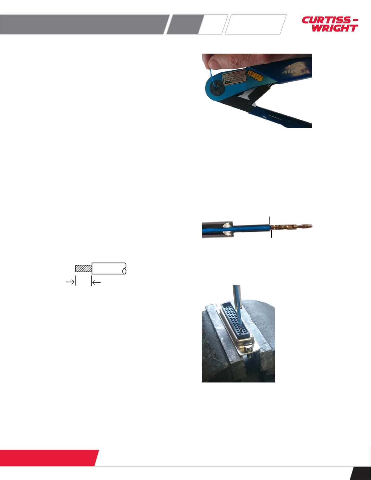
Contact insertion
1. Place the insertion tip (ACD/TOL/002) in the inser-
tion/extraction handle (ACD/TOL/005).
2. Place the wire along the grove in the insertion tip so that
the tip butts up against the crimp pot as shown below.
3. Place the connector in a vice and using a firm, steady
pressure, while keeping the tool perpendicular, push the
contact into the cavity until the contact locks into place.
The shoulder of the tool tip bottoms against the rear of
the insulator, preventing over-insertion.
4. Repeat these steps for other wires to be populated.
0.16 inch (4 mm)
Insertion tip
Crimp pot


