Curtiss-Wright 2600 Series User manual

0713T R0
Series 2600
Maintenance Manual

2
Series 2600 Table of Contents 1. Introduction
1. Introduction ...........................................................................................2
2. Safety Warning and Instruction System.............................................. 3-4
3. Serial and Type Numbering Sytems ................................................... 5-7
4. Valve Cross-Section, Parts and Construction.................................... 8-10
5. Valve Removal and Pre-Inspection................................................. 11-12
6. Disassembly Instructions ............................................................... 13-15
7. Cleaning and Inspection.......................................................................16
8. Maintenance and Repair Procedures ............................................. 17-18
9. Assembly Instructions.................................................................... 19-21
10. Setting, Testing and Adjustments ................................................. 22-26
11. Troubleshooting .................................................................................27
Appendix A: Valve Terminology ................................................................28
Appendix B: Bellows Construction............................................................29
Appendix C: O-Ring Construction....................................................... 31-32
Appendix D: Cap Construction ...........................................................33-35
Appendix E: Critical Dimensions......................................................... 36-43
Appendix F: Maintenance & Inspection Specification Record ...................44
Appendix G: Required Tools .....................................................................45
Appendix H: Torque Values.......................................................................46
This maintenance manual is provided because you have Farris Engineering
2600 Series pressure relief valves protecting equipment and personnel in
your plant. We trust that you will find this manual useful, as it is intended
to clearly present all the essential information you will need in order to
keep your Farris valves in perfect operating condition.
Any maintenance and repair work or testing performed on Farris pressure
relief valves should be done in strict accordance with the requirements of
all applicable Codes and Standards. Persons performing the work should
maintain proper authorization through applicable governing authorities.
To ensure reliable and safe operation, installation, testing, maintenance,
adjustment, and repair of Farris valves, these activities shall only be
performed by qualified personnel having the required skills and training.
No repair, assembly, adjustment or testing performed by individuals other
than Farris-authorized representatives shall be covered by the warranty
extended by Farris to its customers. All applicable regulations, directives,
codes and standards shall be adhered to when performing these activities.
Failure to follow proper test procedures or failure to use proper test
equipment will lead to incorrect test results, damage to the valve and will
invalidate the warranty.
Farris Engineering provides programs which coordinate classroom and
hands-on training. It is recommended that individuals performing pressure
relief valve maintenance receive training specific to those valve series they
expect to repair and set. Only this type of training will ensure the proper
application of these instructions. The National Board of Boiler and Pressure
Vessel Inspectors conducts training programs on valve repair in conjunction
with their VR program. This is a broad-based program and is recommended
to supplement training received from specific manufacturers.
These instructions do not cover all details or variations in equipment,
nor do they provide for every possible contingency to be met in regards
to installation, operation or maintenance. Should further information be
desired or should particular problems arise which are not covered
sufficiently for the purchaser’s purposes, please contact Farris Engineering.

3
2. Safety Warning and Instruction System
You will find safety warnings and instruction labels throughout this manual. These have been included to
ensure your safety and must be followed. Safety labels are vertically oriented rectangles as shown in the
samples below. These labels consist of three panels inside a border. Each safety label will communicate the
following three key pieces of information. This information is communicated using narrative and pictorials.
The nature and severity of the hazard
The consequence of the hazard, if not avoided
The precautions and measures required to avoid the hazard.
The top panel of the safety label illustrates the signal word (DANGER, WARNING, or CAUTION) which
communicates the severity of the hazard, per the above explanations. The center panel contains a pictorial
which communicates the nature of the hazard, and the possible consequence of hazard, if not avoided. In
some cases, the pictorial may depict the precautions or measures required to avoid the hazard. The bottom
panel will then contain the remaining narrative information needed to ensure all three key pieces of
information have been conveyed.
General Safety Instructions
The maintenance manual is provided by Farris Engineering, a business unit
of Curtiss-Wright Flow Control Company, to its customers as general
guidance for the repair and maintenance of Farris valves described herein.
Pressure relief/safety valves are critical components in pressurized
systems to ensure the safety of people, the environment, and property.
Always follow all manufacturer and industry standard recommendations
relating to proper installation, testing, maintenance, and reconditioning.
This manual should not be considered an exhaustive manual. Certain
configurations, applications, and usages may not be covered. If there is
specific information needed which is not covered in this manual, the
customer is advised to contact Farris using the contact information on the
back of this manual. All information presented in this manual is subject to
change without notice. The purchaser should contact Farris regarding any
possible changes in information or specifications.
To ensure reliable and safe operation, installation, testing, maintenance,
adjustment, and repair of Farris valves, these activities shall only be
performed by qualified personnel having the required skills and training.
DANGER:
Indicates hazards which, if not
avoided, will result in death
or serious injury.
WARNING:
Indicates hazards which, if not
avoided, could result in death
or serious injury.
CAUTION:
Indicates hazards which, if not
avoided, could result in minor
or moderate injury.
NOTICE:
“NOTICE” is reserved for
instructions given to prevent
property, product, or
environmental harm.
SAFETY INSTRUCTIONS:
“SAFETY INSTRUCTIONS” indicates
processes or procedures recom-
mended to ensure safety.
No repair, assembly, adjustment or testing performed by individuals other
than Farris-authorized representatives shall be covered by the warranty
extended by Farris to its customers. All applicable regulations, directives,
codes and standards shall be adhered to when performing these activities.
Failure to follow proper test procedures or failure to use proper test
equipment will lead to incorrect test results, damage to the valve and will
invalidate the warranty.
Likewise, use of parts in any maintenance or repair activity other than
factory-supplied OEM parts will invalidate the warranty extended by Farris
to its customers. Incorrect selection or application of Farris valves on the
part of the customer is not covered by the warranty extended by Farris to
its customers.
These general safety instructions have been provided not only to protect
the product and warranty but also are provided for an individual’s personal
safety in handling Farris pressure relief valves. Failure to follow these
procedures could result in severe bodily harm or even death.
Content included here will
describe the nature of the
dangerous condition and/or
how to prevent the danger
hazard from occurring.
DANGER
Content included here will
describe the nature of the
warning condition and/or
how to prevent the warning
hazard from occurring.
WARNING
When using cleaning solvents,
take precautions to protect
yourself from potential danger
from breathing fumes,
chemical burns, or explosion.
Dispose of the waste
according to applicable
rules and regulations.
CAUTION
Content included here
will describe instruction
regarding how to prevent
property, product or
environmental harm.
NOTICE
Content included here will
describe processes or
procedures which ensure
safety if properly followed.
SAFETY
INSTRUCTIONS

4
All possible hazards may not be identified in this manual. Conduct
your own safety risk assessment given your specific system,
environment, and configuration, and ensure proper control proce-
dures are in place to prevent personal injury or illness and property,
product or environmental harm.
When the valve is under pressure, do not place any part of your body
near or in the path of the outlet of the main valve or other discharge
areas. Doing so will result in serious injury or death upon release.
If a test gag is provided with the valve, it must be removed prior to
service installation. Failure to do so will result in equipment failure,
serious injury or death in the instance of an overpressure event.
In certain applications it may be impossible to remove the valve from
service. Never attempt to remove, adjust, maintain, or repair a pressure
relief valve either while it is installed in a pressurized system or on a
test stand, unless you have been properly trained to do so. Doing so
may result in serious injury or death. Ensure the proper isolation of
energy sources and residual pressures by complying with all local, state
and country-specific regulations/directives applying to energy control
procedures and “lockout/tagout.”
Ensure that the pressure relief valve and system is at an ambient
temperature before inspecting, servicing, or repairing. The valve,
system, and contents may be extremely hot or cold. Failure do so may
result in serious injury.
The exhaust from the main valve outlet or any other ports that could
exhaust, should be vented to a safe location to eliminate the potential
for serious injury or damage during relief operation.
Prior to valve disassembly, ensure that proper controls are implemented
to address potential exposures to hazardous substances, including
gases, liquids, or process byproducts contained in or contaminating the
valve. Consult applicable material safety data sheets (MSDSs) and
established exposure limits for the substances expected to be present
to ensure proper exposure controls are implemented. Failure to do so
could result in serious injury or illness.
Ensure the valve is operable at all times and free of potential obstruc-
tions due to the conditions of use, or process fluid obstructions resulting
from solidifications, byproducts, polymerization or other obstructions.
Failure to do so could render the valve inoperable, leading to serious
injuries or damage in the event of system over-pressurization.
Use extreme caution when inspecting a pressure relief valve for
leakage. Never use body parts to inspect for flow leaks. Doing so could
result in serious injection, burn, or chemical injuries.
Use all appropriate personal protective equipment to protect against
process hazards, including but not limited to, pressurization, tempera-
ture extremes, noise, and chemical hazards. Failure to do so could result
in serious injury or death.
Always use the appropriate tools, and in the correct manner, for
adjustment or servicing of valves. Failure to do so could result in injury.
It is the responsibility of the customer and user of Farris valves to
properly train their personnel on all required safety standards and
procedures to prevent injuries and illnesses.
DANGER
WARNING
CAUTION
SAFETY
INSTRUCTIONS

5
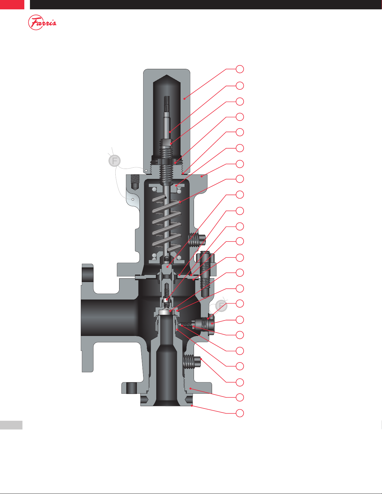
Familiarity with Farris valve type and serial numbering systems will greatly
benefit anyone using this manual or any other Farris literature. The ability
to recognize certain valve types and construction features along with
identifying serial numbers will assist correct maintenance procedures and
spare part selection/ordering. All Farris valve nameplates contain a specific
valve type number and serial number unique to that particular valve. See
Figure 1.2 on page 6 for an example of a typical 2600 Series nameplate.
Serial Numbering System
Each Farris pressure relief valve is assigned a unique serial number. This
serial number is assigned by the factory and remains part of the factory
records. Providing this serial number to the factory will assist in the
identification of the construction and metallurgy of the valve in question.
The following outline will give general guidelines on the serial numbering
system used on 2600 Series valves.
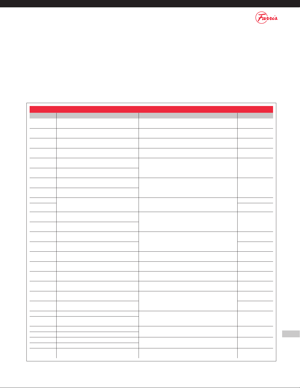
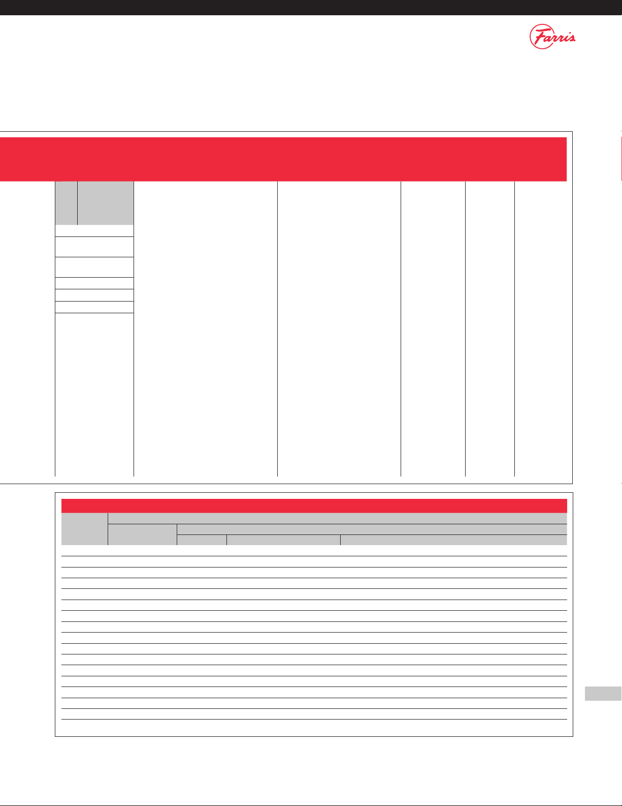
3. Serial and Type Numbering Systems
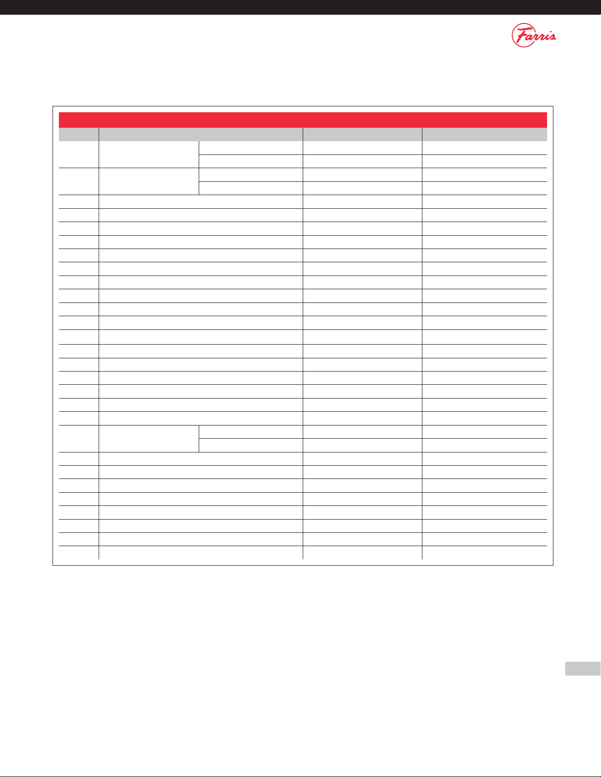
Serial Suffix Summary For 2600 Maintenance Manual
Serial # Suffix Valve Type Description Production Dates
-A15/H 2600L BalanSeal “O” Ring Seat Design
(Liquid Service)
Improved “G” orifice (150# & 300# Class only)
and “F” orifice designs.
2006 - present (G)
2011 - present (F)
-A14/H 2600L Conventional “O” Ring Seat Design
(Liquid Service)
Improved “G” orifice (150# & 300# Class only)
and “F” orifice designs.
2006 - present (G)
2011 - present (F)
-A15/G 2600L BalanSeal Metal Seat Design (Liquid Service) Improved “G” orifice (150# & 300# Class only)
and “F” orifice designs.
2006 - present (G)
2011 - present (F)
-A14/G 2600L Conventional Metal Seat Design
(Liquid Service)
Improved “G” orifice (150# & 300# Class only)
and “F” orifice designs.
2006 - present (G)
2011 - present (F)
-A15/M 2600L BalanSeal Design - “O” Ring
(air, steam, vapor & liquid services) Modified “D” through “K” orifice “O” ring seat design that replaced
original A14 & A15 “O” ring seat design.
Starts at Serial #’s above 300000.
July 1993 - present
-A14/M 2600L Conventional Design - “O” Ring
(air, steam, vapor & liquid services)
-A15 2600L BalanSeal Design
(air, steam, vapor & liquid services) Full nozzle valves conforming to API Standard 526 with ASME
Section VIII certification for liquid service.
Air & steam certification added in 2005.
1985 - present
-A14 2600L Conventional Design
(air, steam, vapor & liquid services)
-A13 2600 & 2600L BalanSeal Piston Design -
All design variations and Services
2600 & 2600L Balanced Piston version of standard 2600
BalanSeal Design. Use of serial suffix changed from A12 to A13
for consistency of numbering system.
Nov. 1997 - present
-A12 1978 - Nov. 1997
-A11/R 2600 BalanSeal Design - “O” Ring
(air, steam, & vapor services) Modified “D” through “K” orifice “O” ring seat design that replaced
the modified A10/M & A11/M “O” ring seat design.
Starts at Serial #’s above 312123.
August 1996 - present
-A10/R 2600 Conventional Design - “O” Ring
(air, steam, & vapor services)
A11/N 2600 & 2600L BalanSeal Design
(air, steam, vapor & liquid services) Special version of 2600 series built to military specifications with
MIL Spec. flanges and semi-nozzle construction
2000 - present
A10/N 2600 & 2600L Conventional Design
(air, steam, vapor & liquid services) 2000 - present
A11/H 2600 BalanSeal “O” Ring Seat Design
(air, steam, & vapor services)
Improved “G” orifice (150# & 300# Class only)
and “F” orifice designs.
2006 - present (G)
2011 - present (F)
A10/H 2600 Conventional “O” Ring Seat Design
(air, steam, & vapor services)
Improved “G” orifice (150# & 300# Class only)
and “F” orifice designs.
2006 - present (G)
2011 - present (F)
A11/G 2600 BalanSeal Metal Seat Design
(air, steam, & vapor services)
Improved “G” orifice (150# & 300# Class only)
and “F” orifice designs.
2006 - present (G)
2011 - present (F)
A10/G 2600 Conventional Metal Seat Design
(air, steam, & vapor services)
Improved “G” orifice (150# & 300# Class only)
and “F” orifice designs.
2006 - present (G)
2011 - present (F)
-A11/M 2600 BalanSeal Design - “O” Ring
(air, steam, & vapor services) Modified “D” through “K” orifice “O” ring seat design that replaced
original A10 & A11 “O” ring seat design.
Starts at Serial #’s above 300000.
July 1993 - July 1996
-A10/M 2600 Conventional Design - “O” Ring
(air, steam, & vapor services) July 1993 - July 1996
-A11 2600 BalanSeal Design (air, steam, & vapor services) Full nozzle valves conforming to API Standard 526 with nozzles
revised to incorporate ASME 0.9 capacity reduction factor. 1976 - present
-A10 2600 Conventional Design
(air, steam, & vapor services)
-A9 BalanSeal Bellows Design Full nozzle valves conforming to API Standard 526. 1959 - 1976
-A8 Conventional Design
-A3, A5, & A7 BalanSeal Bellows Design Includes both 2605 & 2675 Series 1955 - 1967
-A2, A4, & A6 Conventional Design
-A Full nozzle valves, conventional and
BalanSeal bellows types.
Serial suffix covers all types of construction including Conventional,
FarriSeal, BalanSeal, enclosed and exposed spring designs. 1943 - 1955
Note: Valves covered by serial number suffixes in RED are for obsolete designs.

6
Orifice
Letter
Area, Sq. In. Area, Sq. mm
API Actual API Actual
D0.110 0.150 71 97
E0.196 0.225 126 145
F0.307 0.371 198 239
G0.503 0.559 325 361
H0.785 0.873 506 563
J1.287 1.430 830 923
K1.838 2.042 1186 1317
L2.853 3.170 1841 2045
M3.60 4.000 2323 2581
N4.34 4.822 2800 3111
P6.38 7.087 4116 4572
Q11.05 12.27 7129 7916
R16.0 17.78 10323 11471
T26.0 28.94 16774 18671
U — 31.5 —203.2*
V — 49.4 —318.6*
W — 63.6 —410.2*
W2 —104.0 —670.8*
X — 113.1 —729.5*
Y — 143.1 —923.0*
Z — 176.7 —1139.7*
Type Numbering System
Our type numbering system simplifies the selection and specifying of Farris pressure relief valves because the digits that comprise a specific type number
have a distinct significance. The digits describe the basic valve series, orifice, seat and internal construction, inlet temperature range, body, bonnet and
spring material, inlet flange class and Code liquid design.
Inlet
Temperature
Range °F
Material
Body &
Bonnet Spring
1-20 to 800 Carbon
Steel
Chrome
Alloy
2** 451 to 800 Carbon
Steel
Chrome
Alloy
3801 to 1000
Chrome
Moly
Steel
High Temp.
Alloy
4* 1001 to 1200 — —
5* 1201 to 1500 Austenitic
St. St.
Inconel
Alloy
1-21 to -75 Use “S3” Trim Options
1-76 to -450 Use “S4” Trim Options
6-21 to -75
3-1/2%
Nickel
Steel
Carbon
Steel
7-76 to -150
3-1/2%
Nickel
Steel
Austenitic
St. St.
8-151 to -451 Austenitic
St. St.
Austenitic
St. St.
Designation
Prefix 26 D A 1
(if applicable)
Series Number Orifice Areas Construction Temperatures & Materials
H*
Set Pressure
Above API 526
SJ
Steam Jacket
HTF
Heat Transfer Fluid
*Available Only on
Q, R, T and U
Orifices
26 AConventional construction
BBalanSeal construction
CConventional with
O-ring seat pressure seal
DBalanSeal with O-ring seat
pressure seal
EBalanSeal with auxiliary
balancing piston
FBalanSeal with auxiliary
balancing piston and
O-ring seat pressure seal
TTeflon seat, conventional
UTeflon seat, BalanSeal
Note: Items listed in RED are for non-current nomenclature designations or options
no longer offered.
*The U – Z orifices are not API standard sizes.
U – Z metric areas = cm2.
This manual only covers maintenance for D – U
orifices. For larger orifices, please consult the factory.
* Temperature ranges 4 and 5 are beyond the scope of
this catalog. Consult the Factory.
** Temperature range 2 is no longer used as the standard
range valve handles temperatures to 800°F.
Figure 1.1 – BalanSeal Identification Plate
Figure 1.2 – Typical Farris Nameplate
Parts Replacement
Valves – If an exact replacement valve is
required, then the valve type, size and serial
number must be specified to ensure proper
dimensions and material being supplied. If a
specific valve is obsolete, a recommendation of
the current equivalent will be made if possible.
Spare Parts – When ordering parts, use part
names as listed in the bills of materials. Specify
valve type, size and serial number. If the serial
number is not available, the original Farris
factory order number will help us supply the
proper part and material.
Springs – Order as an assembly to include spring with upper and lower
spring buttons. Specify valve type, size, serial number, set pressure and
backpressure, if any.
Note: If valve modification or set pressure changes are required, consideration must be
given to correct the nameplate and other data.
OEM parts only!
NOTICE
Failure to use Farris OEM
parts can create dangerous
operating conditions, poor
valve performance and will
void the warranty.

7
ANSI Nominal
Inlet Flange Class
0150
1300 lightweight
valve
2300 heavyweight
valve
3600
4900
51500
62500
Designation
Prefix 26 D A 1
(if applicable)
Series Number Orifice Areas Construction Temperatures & Materials
H*
Set Pressure
Above API 526
SJ
Steam Jacket
HTF
Heat Transfer Fluid
*Available Only on
Q, R, T and U
Orifices
26 AConventional construction
BBalanSeal construction
CConventional with
O-ring seat pressure seal
DBalanSeal with O-ring seat
pressure seal
EBalanSeal with auxiliary
balancing piston
FBalanSeal with auxiliary
balancing piston and
O-ring seat pressure seal
TTeflon seat, conventional
UTeflon seat, BalanSeal
2L - 1 2 0 /S4
Inlet Class
Special
Construction (if applicable) Inlet Facing Cap Construction Test Gag
Special
Material
AExpanded API sizes: air, steam
and gas service*
BExpanded API sizes: ASME liquid valve*
CExpanded API sizes: ASME Code Section
VIII exposed spring design*
DValve suitable for heat transfer
service-vapor
EValve suitable for heat transfer
service-liquid
FExpanded API size valves suitable for heat
transfer service-vapor*
GExpanded API size valves suitable for heat
transfer service-liquid*
HIntegral steam jacket expanded API Sizes
– Vapor Service
JIntegral steam jacket Vapor Service
KIntegral steam jacket – Liquid Service
LASME Code certified for liquid, air and
steam service
SASME Code Section VIII exposed
spring design
XIntegral steam jacket expanded API sizes
– Liquid Service
*Letter suffixes for expanded API sizes where
2-1/2" inlet or outlet has been replaced by 3" size.
0Special2
1Raised Face, ANSI Std.
(125 to 160 AARH)
2Large Female, ANSI Std.
3Small Male, ANSI Std.
4Small Female, ANSI Std.
5Large Tongue, ANSI Std.
6Large Groove, ANSI Std.
7Small Tongue, ANSI Std.
8Small Groove, ANSI Std.
9Ring Joint (octagonal),
ANSI Std.
A125 AARH Smooth Finish
B125 AARH (Outlet Only)
C125 to 160 AARH (Inlet & Outlet)
(now indicated by a ‘1’)
H63-83 AARH Smooth Finish RF
The following designation can apply to
inlet and/or outlet:
J63 to 83 AARH (outlet only)
K63 to 83 AARH (inlet & outlet)
XHigh pressure hub style connection
2Screwed Cap
3Bolted Cap
4Packed Lever
5L Type Packed
Lever
6R Type Packed
Lever
7Open Lever
8Remoter
(with Packed
Lever)
0Without
Gag
1With Gag
See “Materials
for Corrosive
Service”
Table below.
1. Spring adjusting screw in standard material
2. The springs shown assume bellows construction. For conventional construction, use Inconel X750.
Materials for Corrosive Service
Designation
Special Material Description
Body Bonnet, Cap Internal Parts
Nozzle & Disc Other Springs & Buttons
/S1 Standard 316 3161316 buttons, Chrome Alloy or High Temperature Alloy Nickel Plated spring
/S2 Standard 316 316 316 buttons, Chrome Alloy or High Temperature Alloy Nickel Plated spring
/S3 316 316 316 316 buttons, Chrome Alloy or High Temperature Alloy Nickel Plated spring
/S4 316 316 316 316
/S5 Standard (NACE) 316 316 & Monel w/Inconel 625 bellows Standard 2
/S6 Standard (NACE) 316 316 SAS w/standard bellows Standard2
/S7 Standard (NACE) 316 316 & Monel w/standard bellows Standard2
/H1 Standard Hastelloy C Standard Standard
/H2 Standard Hastelloy C Hastelloy C & Monel 316 buttons, Chrome Alloy or High Temperature Alloy Nickel Plated spring
/H3 Hastelloy C®Hastelloy C Hastelloy C 316 buttons, Chrome Alloy or High Temperature Alloy Nickel Plated spring
/H4 Hastelloy C Hatelloy C Hastelloy C Hastelloy C
/M1 Standard Monel Standard Standard
/M2 Standard Monel Monel 316 buttons, Chrome Alloy or High Temperature Alloy Nickel Plated spring
/M3 Monel Monel Monel 316 buttons, Chrome Alloy or High Temperature Alloy Nickel Plated spring
/M4 Monel Monel Monel Inconel spring, Monel buttons
/N1 Carbon Steel (NACE) 316 (NACE) 3161Standard2
/N4 316 (NACE) 316 (NACE) 31613162

8
General Notes:
The safety valve cross-section illustrated is typical and actual construction details will vary depending on valve size and pressure rating.
Consult the other illustrations contained elsewhere in this manual for greater detail or consult the factory for a cross-section drawing for the actual valve size and pressure rating.
Figure 4.1
4. Valve Cross-Section, Parts and Construction
3
5
1
28
7
13
25
24
12
9
10
11
21
17
2
8
14
19
20
23
22
6
4
Cap
Stem
Spring Adjusting Screw
Jam Nut (S.A.S.)
Cap Gasket
Spring Button
Bonnet
Spring
Stem Retainer
Sleeve Guide
Lock Screw
Bonnet Gasket
Body Gasket
Disc
Disc Holder
Lock Screw Gasket
Lock Screw (B.D.R.)
Hex Nut
Lock Screw Stud
Blow Down Ring
Pipe Plug
Body
Nozzle

9
Table 4.1
General Notes:
Parenthesis in type number indicates orifice designation and valve construction, example: 26FA10
Valve Bill of Materials
Item Part Name Conventional (A10) Material BalanSeal (A11) Material
1Body 26( )( )10 thru 26( )( )16 SA-216 Gr. WCB, Carbon Steel SA-216 Gr. WCB, Carbon Steel
26( )( )32 thru 26( )( )36 SA-217 Gr. WC6, Chrome Moly SA-217 Gr. WC6, Chrome Moly
2Bonnet 26( )( )10 thru 26( )( )16 SA-216 Gr. WCB, Carbon Steel SA-216 Gr. WCB, Carbon Steel
26( )( )32 thru 26( )( )36 SA-217 Gr. WC6, Chrome Moly SA-217 Gr. WC6, Chrome Moly
3Cap Carbon Steel Carbon Steel
4Disc 316 St. St. 316 St. St.
5Nozzle 316 St. St. 316 St. St.
6Disc Holder 316 St. St. 316 St. St.
7Blow Down Ring 316 St. St. 316 St. St.
8Sleeve Guide 316 St. St. 316 St. St.
9Stem 316 St. St. 316 St. St.
10 Spring Adjusting Screw Stainless Steel Stainless Steel.
11 Jam Nut (S.A.S.) 316 St. St. 316 St. St.
12 Lock Screw (B.D.R.) 316 St. St. 316 St. St.
13 Lock Screw Stud 316 St. St. 316 St. St.
14 Stem Retainer 17-4 Ph. St. St. 17-4 Ph. St. St.
15 Bellows (not shown) N/A Inconel Composite
16 Bellows Gasket (not shown) N/A Non-Asbestos
17 Spring Button Carbon Steel, Rust Proofed Carbon Steel, Rust Proofed
18 Body Stud ASME SA-193 Gr. B7, Alloy Steel ASME SA-193 Gr. B7, Alloy Steel
19 Lock Screw (D.H.) Stainless Steel Stainless Steel
20 Spring 26( )( )10 thru 26( )( )16 Chrome Alloy Rust Proofed Chrome Alloy Rust Proofed
26( )( )32 thru 26( )( )36 High Temp. Alloy Rust Proofed High Temp. Alloy Rust Proofed
21 Cap Gasket 316 St. St. 316 St. St.
22 Body Gasket 316 St. St. 316 St. St.
23 Bonnet Gasket 316 St. St. 316 St. St.
24 Lock Screw Gasket 316 St. St. 316 St. St.
25 Hex Nut (B.D.R.L.S.) Stainless Steel Stainless Steel
26 Hex Nut (Body) ASME SA-194 Gr. 2H, Alloy Steel ASME SA-194 Gr. 2H, Alloy Steel
27 Pipe Plug (Bonnet) Steel N/A
28 Pipe Plug (Body) Steel Steel

10
Figure 4.2 Figure 4.3
Internals for Orifice D-J Internals for Orifice K-P
BalanSeal®Bellows Safety ValveInternals for Orifice Q-U
Figure 4.5Figure 4.4

11
5. Valve Removal and Pre-Inspection
General Handling:
After the pressure relief
valve is removed from
the installation it should
be transported to the
shop for inspection,
testing, maintenance,
and resetting. Careful
handling in transit is
important, as rough
handling can change
the pressure setting or deform the pressure
relief valve parts so they cannot be set or
function properly. Flanges on the piping and
flange faces on the valve should be protected
so that gasket faces are not damaged. Large
valves should be handled with suitable rigging
equipment to avoid dropping or rough handling.
Pressure relief devices should not be stocked in
a careless manner and, where practical, they
should be segregated and not stored with
heavy pipe fittings or other types of valves.
Pressure relief valves should be treated as
delicate instruments because their accurate
functioning is very important to safe plant operation.
Because cleanliness is essential for the satisfactory operation and
tightness of a pressure relief valve, all necessary precautions should be
taken to keep out foreign materials. Valves which are not installed soon
after repair should be closed off properly at both inlet and outlet flanges.
Particular care should be taken to keep the valve inlet and internals
absolutely clean. Preferably, valves should be stored indoors or in locations
where dirt and other forms of contamination are at a minimum. Valves
should be handled carefully and not subjected to heavy shocks. If due
consideration is not given to this point, some internal damage or
misalignment can result and seat tightness may be adversely affected.
Store, transport and install valves with the stem in the vertical position.
In practice, a repaired pressure relief valve including one that has been
only cleaned or readjusted is called upon to provide the same degree of
protection as a new valve. It follows that maintenance personnel must be
trained to a level of proficiency that enables them to restore a valve to
original condition and function. It is recommended that historical records
be established and maintained including test reports. This will provide data
to determine the frequency of inspection and repair for various services.
One excellent publication for reference on pressure relieving devices is the
American Petroleum Institute’s (API) Recommended Practice RP 576,
Inspection of Pressure-Relieving Devices. The use of original manufac-
turer’s replacement parts is necessary to maintain new valve performance,
capacity flow and warranty. Farris Engineering expressly voids its warranty
and will not be responsible for faulty valve operation if non-factory
replacement parts or methods are utilized in product repair.
Field Removal
A visual inspection of pressure relief valves should be made when the
valves are first removed from the system. Many types of deposits or
corrosive debris may be loose and drop out from the pressure relief valve
while it is being transported to the shop. When fouling is a frequent
problem, it may be desirable to collect samples for further testing and to
make notes regarding deposit location and appearance. Any obstructions
in the valve should be noted and corrected.
NOTICE
Only lift PRV vertically.
NOTICE
Do not lift the valve by
the lever.
Use properly designed
and rated rigging/lifting
equipment. Failure to do so
could cause serious injury
or death.
DANGER

12
Inspection of Inlet and Outlet Piping
When a pressure relief valve is removed from service, the upstream and
downstream piping is often open and available for inspection. However,
where it is the practice to remove pressure relief devices from equipment
during operation by closing block valves, it is usually not possible to make
a complete inspection of piping. Such inspection should be made when
the operation equipment is out of service. Inspection of the piping at the
pressure relief valve will often indicate the condition of other process
piping which is not readily available for inspection. Piping should be
checked for corrosion, indications of thinning and deposits which may
interfere with valve operation. The characteristics of the deposits may supply
clues regarding leakage from the pressure relief valve in a closed system.
In-Situ Testing
In-situ or in place testing is frequently
performed as a substitute for valve removal and
in-shop testing. This should not be considered
as equivalent to shop maintenance; however it
may be employed under controlled situations to
extend the shop service frequency of particular
valves. The most common method of in-situ
testing employs an external power source
applied to the valve to determine the valve set
pressure at some lower system pressure. While
this method can accurately determine the valve
set pressure, valve reseat pressure cannot be determined using the
method. Care must be exercised with this method to avoid possible valve
damage that may go undetected during the in-situ test.
In-Shop Inspection
When a valve is first received in the shop it should be given a visual
inspection to note its condition when removed from service. The results
of this inspection should be noted on appropriate forms. It is generally
considered important to determine the set pressure of the valve when
removed from service and prior to the valve being disassembled. If the
valve opens at the set pressure, the valve need not be tested further to
determine the as-received relieving pressure. If the initial pop is higher
than the set pressure, it is advisable to test a second time. If the valve then
pops at approximately the set pressure, this indicates that the valve was
probably stuck because of deposits. If the valve does not pop near the set
pressure, this indicates that the valve setting was either in error originally
or may have been changed during operation.
Valves which are found acceptable upon shop pre-test cannot be returned
to service with a National Board “VR” stamp being applied unless they are
completely disassembled and complete repairs are undertaken. Some
maintenance programs may however authorize valves found acceptable
on shop pretest to be returned to service based on historical records,
tear-down cycles and all seals and valve identifications remaining intact.
Preparation For Maintenance
Before valve teardown is performed a review of previous maintenance
records will assist in an understanding of past valve performance, settings
and maintenance requirements. A complete maintenance records
management system will allow proper stocking of common replacement
items such as gaskets and seals and adequate stocking of major
replacement parts such as nozzles, discs, and springs. Maintenance
records, when properly updated, can serve to identify the need for ordering
spare parts when valve servicing shows that the useful life of a particular
part has been reached. Rework details and installation of new parts should
be recorded to aid future service activities.
NOTICE
Use care to avoid possible
PRV damage during In-Situ
testing.

13
6. Disassembly Instructions
General Disassembly of Valves
After the valve is received and checked it is ready for shop inspection and
repair. The valve should be carefully dismantled. If you are unfamiliar with
this line of Farris valves carefully study the cross-sectional drawings in
Figures 4.1 through 4.5 to familiarize yourself with part terminology and
location. Proper facilities should be available for segregating parts as the
valve is dismantled. At each stage in the dismantling process, all parts of
the valve should be visually inspected for evidence of wear and corrosion.
If parts are worn, replace them. See Appendix G for necessary tools.
The following general points will provide a brief checklist to follow during
disassembly. Detailed discussion will follow for specific critical parts.
Check for the presence of wire seals at all
points of adjustment.
Check for complete and properly identified
nameplates and tags.
Check the condition of flanges; look for
evidence of pitting, roughening, deterioration
of gasket surface, distortion, etc.
Visually inspect springs for evidence of
corrosion, cracking, and correct selection.
Visually inspect bellows (if the valve is of
bellows type).
Examine o-ring condition (if applicable).
Visually inspect inlet and outlet openings; look for evidence of deposits
of foreign material and for corrosion. Note the condition of external
surfaces and look for any indication of corrosion or evidence of
mechanical damage.
Check and note the body, nozzle and bonnet wall thickness, thread
and stud condition.
Verify valve components and material and check against
nameplate information.
Disassembly Instructions:
Farris 2600 Series valves should be disassembled
as described below. Parts identification may be
found in Figure 4.1 on page 8. The parts from
each valve should be properly marked and
segregated to keep them separate from parts
used in other valves.
1. Cut the wire seals and remove the Cap [3] and
Cap Gasket [21]. For valves equipped with a
lifting lever, follow the instructions in Appendix D.
(Figure 6.1)
2. Before loosening the Jam Nut [11], measure the location of the Spring
Adjusting Screw (SAS) [10] by marking the SAS [10] above the Jam
Nut [11]; or by counting the number of counter clockwise revolutions of
the SAS [10] until the Spring [20] is no longer compressed. This will
allow the approximate set pressure to be re-established when
reassembling the valve. (Figure 6.2)
3. Remove the Jam Nut [11] and SAS [10].
Figure 6.2
Stem
Jam Nut
Bonnet
Spring
Adjusting
Screw
Mark with
Paint or
Marker
Measure
Figure 6.1
Be aware that process
fluids may be trapped inside
the cap and bonnet. Use
appropriate PPE as required.
WARNING
A PRV is under spring load.
Ensure disassembly
procedures are followed
carefully to avoid serious
injury or death.
DANGER

14
Figure 6.4
Stem Retainer
Sleeve Guide
Stem
Disc Holder
4. Remove the Blow Down Ring Lock Screw assembly [12,13, 25] and Lock
Screw Gasket [24]. Record the position of the Blow Down Ring [7] with
respect to the Disc Holder [6] by counting the number of notches required to
raise the ring until it just touches the Disc Holder [6]. This information will be
needed again when reassembling the valve. (Figure 6.3)
5. Remove the Body Hex Nuts [19]
6. Record the position of the bonnet drain relative to the valve outlet and
remove the Bonnet [2].
a. On larger valves, the combination of bonnet weight and the height that it
must be lifted to clear the Stem [9] requires that a hoist be used to remove
the Bonnet [2]. During this operation, the valve Body [1] should be
secured to prevent it from tipping over once the Bonnet [2] is removed.
b. Use care when lifting the Bonnet [2] as the Spring [20] and Stem [9]
will be able to tip over.
7. Remove the spring assembly (Spring [20] and Spring Buttons [17])
from the Stem [9]. The spring assembly must be kept together. The
Spring Buttons [17] should be tagged for later identification as the
upper and lower buttons may not be identical.
8. Using the Stem [9] as a handle, lift the complete internal assembly
from the valve Body [1]. (Figure 6.4)
a. On larger valves a hoist is advisable due to the weight of the
internal assembly.
b. An eye bolt may be attached to the stem test washer thread at the
end of the Stem [9] to assist in lifting.
c. For balanced bellows valves, use care not to damage the
bellows assembly.
d. If parts are difficult to remove due to the presence of corrosive or
foreign material soaking in a suitable solvent may be required.
9. Remove the Body Gasket [22] and Bonnet Gasket [23].
10. To remove the Stem [9] from the Stem Retainer [14], lift up on the
Stem [9] while holding the Stem Retainer [14] down and rotate
counter-clockwise at the same time. This will engage the thread.
Continue rotating until the Stem [9] is removed. (Figure 6.5)
Figure 6.3
Lock Screw Stud
Hex Nut
(B.D.R.L.S.)
Lock Screw
Gasket
Lock Screw
(B.D.R.)
Figure 6.5
Stem
Stem Retainer

15
Figure 6.6
Stem Retainer
Disc
Disc Holder
Figure 6.8
Stem Retainer
Disc Holder
Lock Screw
11. Remove the Disc [4] from the Disc Holder [6] (Figure 6.6).
a. Hold the assembly and rotate the Disc [4] with the tip of your finger.
b. For o-ring seat type valves, refer to Appendix C for instructions.
12. To separate the Disc Holder [6] from the Stem Retainer [14], first
thread the lock screw up into the Stem Retainer [14] using the fixture
shown in Figure 6.7 to hold the assembly.
a. Except for the D & E orifice bellows (A11) designs which have a one
piece stem retainer/disc holder, the Stem Retainer [14] and Disc
Holder [6] are held together with a Disc Holder Lock Screw [26].
b. The Disc Holder Lock Screw [26] has a hex socket requiring the
use of an Allen key (Figure 6.8).
c. Locking tension is relieved by threading the lock screw UP INTO the
Stem Retainer [14].
d. Allen key wrench sizes are shown in Table 6.1.
e. Be careful not to damage the guiding surface of the
Stem Retainer [14] during disassembly.
f. For bellows valves see Appendix B.
13. Remove the Blow Down Ring [7] from the Nozzle [5].
14. Turn the valve Body [1] over and re-clamp to the work bench. With a
spanner wrench and mallet, remove the Nozzle [5] from the Body [1]
a. Some valves may use wrenching flats instead of spanner holes.
NOTES:
1. For BalanSeal Bellows construction, please see Appendix B for
disassembly instructions.
2. For O-Ring seat construction, please see Appendix C for disassembly
instructions.
3. For open lever, packed lever and bolted cap construction, please
see Appendix D for disassembly Instructions.
Allen Key Sizes
Disc Holder Lock Screw
Orifices Allen Key Size
D thru J 3/16"
K thru P 7/32"
Q thru T 3/8"
Figure 6.7
Table 6.1

16
7. Cleaning and Inspection
7.1 Cleaning
Blast Cleaning
2600 Series body, bonnet and cap castings can be sand or bead blasted. When
blast cleaning, exercise caution to protect internal and machined surfaces to
avoid causing damage. Protect the nameplate prior to blast cleaning. It is not
recommended to blast internal parts.
Brush Cleaning
Internal parts (except for guiding surfaces) and the inside of the body and
bonnet castings can be cleaned with a wire brush and/or grinder until they are
clean. Exercise caution when brush cleaning to avoid damaging or eroding the
parts. Only clean stainless steel brushes should
be used on stainless steel components.
Immersion/Washing
Castings and internal parts should be
thoroughly cleaned with an appropriate
solvent or cleaning solution. After immer-
sion/washing, ensure that any residue is
removed and parts are dried completely.
Polishing
Guiding surfaces on the stem, stem retainer and
guide can be polished using a fine emery cloth.
7.2 Inspection
Check all valve parts for wear and corrosion.
Inspection of valve components is important to
ensure proper valve performance. Damaged
valve parts must be repaired or replaced
with OEM parts.
The valve seat (nozzle and disc) must be
examined to determine if they have been
damaged. Typically, lapping the nozzle and/or
disc is all that is needed to restore these parts to
their original condition. Prior to lapping, or If
machining is necessary, consult section 8 and
Appendix E, Critical Dimensions.
The valve spring should be inspected for evidence of cracking, pitting, corrosion
or deformation. If any of these are found, the spring should be replaced.
The guiding surfaces on the sleeve guide and stem retainer should be
checked for evidence of pitting, corrosion, distortion or galling. If found,
these parts should be replaced.
Stems should be inspected as follows:
1. Check the bearing point on the stem tip for a smooth surface. Lap if
necessary against the mating part to improve the surface. If the
spherical contact is destroyed, the stem should be replaced.
2. Check the critical stem areas for concentricity using the following
procedures (Figure 7.1 and 7.2):
a. Using “V”-Blocks or bench rollers, check the stem at the midpoint
and also at the lower spring button radius for any runout.
b. By applying a machinist’s dial indicator and rotating the stem,
the total indicator reading should not exceed 0.007 inches.
Straighten if necessary.
3. The top area of the stem just below the threads serves as the valve’s
upper guiding surface in conjunction with the spring adjusting screw.
This area is supplied from the factory with a 63 AARH finish. This area
should be free from any signs of galling, corrosion, distortion or pitting.
If seen, the stem should be replaced.
For BalanSeal valves, the bellows should be inspected for evidence of
cracking, pitting, corrosion or deformation that might develop into a leak.
Check and inspect all gaskets for evidence of damage or corrosion.
Typically, gaskets should be replaced prior to assembly.
Figure 7. 2
Figure 7.1
Bench Rollers
Stem
Place Dial
Indicator
Here
Spring
Button
Seat
A
When using cleaning solvents,
take precautions to protect
yourself from potential danger
from breathing fumes,
chemical burns, or explosion.
Dispose of the waste
according to applicable
rules and regulations.
CAUTION
OEM parts only!
NOTICE
Failure to use Farris OEM
parts can create dangerous
operating conditions, poor
valve performance and will
void the warranty.

17
8. Maintenance and Repair Procedures
Nozzle Refacing
1. Prior to refacing the nozzle seating area, grip
the nozzle flange in a lathe chuck fitted with
soft jaws (preferably with removable top
jaws), and bored on each set-up to fit the
nozzle flange outside diameter.
2. True up the nozzle by means of an indicator,
ensuring that the nozzle bore and the
machined surface between the nozzle
threads and body sealing surface are
concentric with each other, within 0.002"
full indicator reading.
3. Machine a light cut across the seat until the damaged areas are removed,
ensuring compliance with Appendix E. The seat should be machined to the
smoothest possible finish. Rigidity of the cutting tool is critical.
4. Relap to the required finish.
5. Discard and replace the nozzle when the length from the seat to the
flange becomes less than the minimum specified by the manufacturer.
Do not reduce the nozzle flange thickness in an attempt to maintain the
“L” dimension. The valve center to face dimension will be altered as a
result and nozzle strength may be impaired.
6. See Appendix E for Critical Dimensions.
Disc Refacing
1. Prior to refacing the disc seating area, grip the disc outside diameter in
a universal three-jaw lathe chuck fitted with soft jaws (preferably with
removable jaws), and bored on each set-up to the disc outside diameter.
Avoid excessive chucking force.
2. True up the disc by means of an indicator, ensuring that the disc outside
diameter and seat face are true with each other within 0.002" full
indicator reading.
3. Machine light cuts across the seat at 90° to the axis until the damaged
areas are removed, facing to the smoothest possible finish. Rigidity of
the cutting tool is critical.
4. Relap flat across the full width of the raised seating surface.
5. Discard and replace the disc when the thickness is less than the value
in Appendix E.
6. See Appendix E for Critical Dimensions.
Lapping Compounds
The three grades of Farris Lapping Compounds are prepared especially for
the requirements of pressure relief valves. These are the only compounds
recommended for achieving extreme valve tightness, These compounds
are available in 2 ounce tubes. Use sparingly.
Lapping Procedures (Manual)
1. Use a cast iron lapping block or Pyrex lapping glass which is known to
have a perfectly flat face.
2. Select the appropriate lapping compound. When lapping the disc,
operate with a light figure eight motion over entire block surface. In this
way complete contact will be made (Figure 8.1).
Farris Lapping Compounds
Part No. Grade Finish Size
18632X1 (055) 3F Roughing 1/2 oz. tube
18633X1 (075) 38-500 Medium 1/2 oz. tube
18634X1 (105) 38-1200 Final 1/2 oz. tube
Figure 8.1
Lapping Plate Part
SAFETY
INSTRUCTIONS
Maintenance and repair
should only be performed
by properly trained and
authorized individuals.
PRV
101

18
3. Lap the disc until all blemishes and score marks have been removed. As
the figure eight motion is executed, frequently lift the disc away from
the block to get a fresh bite on the compound. Most important, do not
contaminate compounds with dirt. Store lapping blocks and lapping
glass in a clean, dust-free area.
4. Follow the same procedure for lapping the nozzle. When lapping
nozzles, the nozzle can be placed on a table and a lapping block placed
on the nozzle. Be sure that the lapping block does not tip over the side
of the nozzle (which would cause rounding of the edges). Use a light,
rapid figure eight stroke, lifting the block from the nozzle occasionally.
5. When finished, be sure that all parts are carefully cleaned of all lapping
compound using a suitable solvent. Residual compound may damage
the seating surfaces during valve operation. When reassembling the
parts in the valve be careful not to scratch or score the seating surfaces.
6. If the nozzle or disc is badly scored or pitted a fine machine cut should
be made to reface the surfaces following instructions in the refacing
section of this manual.
Lapping Procedures (Machine)
Lapping machines come in a variety of styles. There are limitations to the
parts that can be lapped, which may be due to constraints of the lapping
machine or the nature of the part to be lapped.
Limitations:
1. The size of the lapping machine.
Obviously, you will be limited by the size of the lapping plate on the
machine. A part that is larger than the lapping plate capacity will have
to be hand lapped.
2. The weight of the part to be lapped.
Some parts will be too heavy to lap on the machine, relative to the area
to be lapped. These parts will have to be hand lapped.
3. How well the part can be balanced on the lapping machine.
Due to geometry and weight distribution of the part, the part may
tend to wobble or fall over in the lapping machine. For these types
of parts a holding fixture should be designed or the part should be
lapped by hand.
General Operation
This is a general procedure for the use of lapping machines. ALWAYS
FOLLOW THE MANUFACTURER’S OPERATING INSTRUCTIONS.
Thoroughly clean all contaminates from the seat area of the nozzle or disc
to be lapped. Place the nozzle or disc seating area on the lapping plate.
Turn on the machine and adjust the flow of lapping fluid which should be
enough to keep the lapping plate covered with a thin film. The lapping
plate should be neither dry nor overly lubricated.
The duration of time that the nozzle or disc should be lapped is dependent
on the weight of the part, the hardness of the material, and the area to be
lapped. A combination of a heavy part with a small area to be lapped made
from a soft material will take the shortest time to lap. A combination of a
light part with a large area to be lapped made from a hard material will
take the longest time to lap.
Once the lapping is complete, remove the nozzle or disc from the lapping
plate and remove the lapping fluid with soft tissue and suitable solvent.
Protect the seating areas with soft tissue covered by a plastic cap.
Lapping Machine Maintenance and Seat Inspection
Seat flatness is critical to achieving leak tight seats. As the width of most
pressure relief valve seats is quite narrow, it is difficult to check seat
flatness directly with a monochromatic light. Instead, a standard test
block should be kept on the lapping machine that can be periodically
checked to determine the condition of the lapping plate. If the test block
“reads” flat then all parts lapped on the machine will also be flat. Since
the lapped surface needs to be reflective in order to “read” the surface
flatness using a monochromatic light source and optical flat, a polishing
stand is a needed accessory. Remove the test block from the lapping
machine and clean off all lapping fluid. Rub the test block on the polishing
stand as if you were hand lapping the test block. Only a few strokes will be
necessary to make the surface reflective enough to allow reading the lines
produced by the monochromatic light. For full details on how to read these
lines and the subsequent adjustments of the machine consult the lapping
machine manufacturer.
The quality of the lapped surface produced by the lapping machine can
only be as good as the level of maintenance of the machine itself.

19
9. Assembly Instructions
Lubrication and Sealant:
Threaded parts should be lubricated to prevent galling, especially parts
made of similar materials. In addition, guides and pivot points should
contain lubricant which is compatible with the service conditions. Sealant
should also be applied to prevent fluid from escaping valve boundaries,
especially if back pressure is present. The adjacent table lists the
suggested lubricant and sealant for air, steam, and liquid service.
Service conditions may dictate that other lubricant or sealant be used.
Code for Above Recommended Lubrication and Sealant
A = Bostic Never Seez
B = Molykote 3452
D = No Lubrication
* Service conditions may require an alternate lubricant or sealant
Item Thread Lubrication Air Steam Liquid
1Pipe Plug/Body A A A
2Lock Screw (BDR) Body A A A
3Blowdown Ring/Nozzle D D D
4Lock Screw Stud/Jam Nut (BDRLS) A A A
5Disc/Disc Holder A A A
6Stem Retainer/Disc Holder (if Applicable) A A A
7Lock Screw (DH)/Stem Retainer A A A
8Stem Retainer/Stem A A A
9Pipe Plug/Bonnet (if applicable) A A A
10 Spring Adjusting Screw/Bonnet/Jam Nut A A A
11 Plain Cap/Bonnet (if applicable) A A A
12 Body Stud/Body/Hex Nut A A A
Guiding and Pivot Lubrication
13 Disc/Disc Holder A A A
14 Sleeve Guide/Stem Retainer D D D
15 Stem Retainer/Stem A A A
16 Spring Button/Stem A A A
17 Spring Button/Spring Adjusting Screw A A A
Sealant
18 Body/Nozzle A A A
19 Body/Bonnet/Sleeve Guide/Gaskets A A A
20 Bonnet/Gasket/Cap (if applicable) A A A
21 Bellows Gasket B B B
Assembly Instructions
Farris 2600 Series valves should be assembled as described below.
Parts identification may be found in Figure 4.1 on page 8.
For torque requirements, please refer to Appendix H.
1. Thread the Nozzle [5] into the Body [1].
2. Thread the Pipe Plug [28] into the Body [1].
3. Thread the Blow Down Ring [7] onto the Nozzle [5].
4. Thread the Hex Nut [25] onto the Lock Screw Stud [13]. Thread the
Lock Screw Stud [13] into the Lock Screw (BDR) [12].
5. Thread the Lock Screw Assembly into the Body [1] including the
Lock Screw Gasket [24]. Adjust the position of the Lock Screw Stud
[13] so that it prevents rotation of the Blow Down Ring [7] yet does
not bind it. Use the position noted during disassembly. (Figure 9.1)
6. Thread the Body Studs into the Body [1].
7. Place the Body Gasket [22] in the Body [1] counter-bore.
8. Thread the Lock Screw [19] into the Stem Retainer [14]. (Figure 9.2)
Figure 9.2
Stem Retainer
Disc Holder
Lock Screw
Figure 9.1
Lock Screw Stud
Hex Nut
(B.D.R.L.S.)
Lock Screw
Gasket
Lock Screw
(B.D.R.)
NOTICE
Only a light film lubricant
should be applied to the
guiding surfaces. Too much
lubricant will hinder valve
performance.
NOTICE
Always use new gaskets
and packing when
reassembling valves.

20
Figure 9.3
9. Thread the Disc Holder [6] onto the Stem Retainer [14] using a
special assembly block (see Figure 9.3). Do not attempt to hold the
Stem Retainer [14] on the guiding surface. Thread the Lock Screw
[19] counter clockwise until contact is made with the Disc Holder [6].
Tighten to lock the assembly together.
10. Thread the Disc [4] into the Disc Holder [6]. Be sure the Disc [4] is
free-floating. (Figure 9.4)
11. Place the Sleeve Guide [8] over the Stem Retainer [14] with the long
lift stop facing down. Be sure that the guiding motion is smooth.
12. Thread the Stem [9] and Stem Retainer [14] together. Be sure this
connection is free-floating. (Figure 9.5)
13. Lower the Assembly (Stem [9], Sleeve Guide [8], and Disc Holder
[6]) into the Body [1] counter-bore. (Figure 9.6)
14. Place the Bonnet Gasket [23] on the Sleeve Guide [8], or secure with
sealant in the Bonnet [2] counter-bore.
15. Place the lower Spring Button [17] on the Stem [9]. Caution – in
some valve sizes the upper and lower Spring Buttons [17] are
different.
16. Place the Spring [20] on the lower Spring Button [17].
Figure 9.6
Stem Retainer
Sleeve Guide
Stem
Disc Holder
Figure 9.4
Stem Retainer
Disc
Disc Holder
Figure 9.5
Stem
Stem Retainer
Table of contents
Other Curtiss-Wright Industrial Equipment manuals
Popular Industrial Equipment manuals by other brands

Emerson
Emerson Daniel 3410 Series Maintenance and troubleshooting manual

HBM
HBM PW27P Series Mounting instructions

Siemens Energy
Siemens Energy SpecTRON 8 Installation & operation manual

Johnson Controls
Johnson Controls ZW Series installation manual

EVAPCO
EVAPCO Mr. GoodTower EAW-FD Series Additional Installation, Operation and Maintenance Instructions

Temptronic
Temptronic ThermoStream TP04100A Operator's manual