Curve Beam pedCAT User manual

90001Rev07.26.13
Computed Tomography
Imaging X-ray System
Operator’s Manual
175TitusAve,Suite300
Warrington,PA18976
Ph:267‐483‐8081
Fax:267‐483‐8086
www.curvebeam.com
CurveBeamTechnicalSupport:267‐483‐8081

1
0473 90001Rev07.26.13
Table of Contents:
ChapterNamePage
Chapter1:
Introduction2
Chapter2:
ProductInformation12
Chapter3:
SafetyItems26
Chapter4:
Calibration&QualityAssuranceProcedures40
Chapter5:
RadiationEnvironmentalSurvey79
Chapter6:
Operations:AcquiringaScan92
Chapter7:UsingtheViewingSoftware:CubeVue
111
AppendixI:InstallationInstructions
143
AppendixII:
Troubleshooting156

2
0473 90001Rev07.26.13
Manual
CHAPTER 1: Introduction
In order to maintain the safety of patient’s and operators of this device, it is important to operate
and maintain the system correctly, following all instructions, warnings, cautions in this manual
and labeling on the system itself. Installation Instructions are detailed in Appendix I.
The PedCAT has been evaluated against European MDD requirements and carries the 0473
mark.
Warnings, Cautions, Advice, and Notes:
Before attempting to operate the equipment, it is recommended that you read this manual
thoroughly including all cautions and warnings. This guide uses the following conventions to
describe situations that are potential hazards to the Patient or Operator, potential loss of data,
or potential damage to the equipment.
WARNING
Warnings are intended to alert the user that failure to follow the procedure could cause fatal or
serious injury to the user, Patient, or any other person, or result in a misdiagnosis.
CAUTION
Cautions are intended to alert the user that failure to follow the procedure could cause damage
to the equipment or cause loss of data.
NOTE
Notes are used to highlight important or unusual points to be brought to the attention of the
operator.
Advice
Refer to user manual.
FortechnicalsupportorquestionscontactCurveBeamat267‐483‐8081

3
0473 90001Rev07.26.13
Safety Precautions:
WARNING The X-ray device is intended to be used for patients 50 lbs (23 kg) to 400 lbs
(181 kg) and groin area at least 22” (56 cm) above the floor. DO NOT use this device for any
patient less than 50 lbs (23 kg) OR groin area less than 22” (56 cm) above the floor, whichever
is more restrictive.
WARNING The patient must wear a protective full wrap X-ray shielding apron (lead apron)
during a scan. Patients less than 21 years old, small size patients (under 100 pounds) and
children must also wear a gonad and ovarian front and back protective shield.
WARNING The X-ray device may be dangerous to the Patient and Operator if you do not
observe and follow operating instructions. Do not operate this system unless you have received
training to perform a procedure.
WARNING Do not remove covers or cables on system. High voltage is present in the
system. To avoid personal injury from electrical shock, do not operate the system with any
covers open or cables removed.
WARNING This device may cause detrimental interaction with active implantable medical
devices and body worn active medical devices. Consult the manufacturer of such devices for
more information.
WARNING Closing of the Gate doors creates a pinch point. Keep hands and feet clear
when closing Gate.
WARNING No modification of this equipment is allowed.
WARNING Service and maintenance can only be performed by CurveBeam authorized
service personnel. ONLY Curvebeam authorized replacement parts can be used in the
equipment. These requirements must be followed in order to avoid a hazard to the equipment,
operator and/or patient.
CAUTION When initiating an exposure, the external Warning Light is activated a few
seconds before the X-ray ON alarm (buzzer) and X-ray ON lights are activated.
CAUTION: Federal law restricts this device to sale by or on the order of a physician.
CAUTION: No auxiliary software should be installed on the system server and thin client
terminals.

4
0473 90001Rev07.26.13
Electrical Hazards:
Installation and system wiring must meet all requirements of local governing authorities. Please
check your local authorities and local codes to determine best practices for a safe installation.
Do not place any liquid or food on any part of the consoles or other modules of the system.
Observe all fire regulations. Fire extinguishers should be provided for both electrical and non-
electrical fires. All operators should be fully trained in the use of fire extinguishers and other fire-
fighting equipment and in local fire procedures.
WARNING In the event of an electrical fire, only use extinguishers that are labelled for that
purpose. Using water or other liquids on an electrical fire can lead to fatal or other serious
personal injury.
WARNING In the event of an electrical fire, to reduce the risk of electrical shock, try to
isolate the equipment from the electric source before attempting to extinguish the fire.
WARNING To avoid risk of electric shock, this equipment must only be connected to a
supply main with protective earth.
Explosion Hazard
Do not use the System in the presence of explosive gases or vapors, including anaesthetic
gases. Use of this system in an environment for which it is not designed can lead to fire or
explosion.
WARNING This unit is not suitable for use in a flammable air mixture environment. If
hazardous substances are detected while the system is turned on, do not attempt to turn off the
system. Evacuate the area and then remove the hazards before turning off the system.
Mechanical Hazards:
WARNING Do not operate the system with any covers open or removed. Operating the
system with open or removed covers could expose mechanical operating systems that could
cause serious or fatal personal injury to you or the Patient. Only qualified and authorized
service personnel should remove covers from the system.
The system is designed to detect that the Gate doors are closed before a scan can initiate. If
the gate doors are not closed, then the gantry will not engage and the x-ray will not initiate.
Laser Beam Hazards:
WARNING Laser beams can cause optical damage. The operator should avoid looking
directly into the beams. The operator should instruct the patient to avoid looking directly into the
beams. The use of optical instruments such as eyeglasses with large diopter or mirrors,
increase eye hazard with this product.

5
0473 90001Rev07.26.13
Radiation Safety:
X-rays are dangerous to both operator and others in the vicinity unless established safe
exposure procedures are strictly observed. Use the following safety measures to ensure safety
to the Patient and Operator. The useful and scattered beams can produce serious or fatal
bodily injuries to Patients and persons in the surrounding area if used by an unskilled operator.
Adequate precautions must always be taken to avoid or reduce exposure to the useful beam or
to scattered radiation. Operators are strongly urged to comply with the current
recommendations of the International Commission on Radiological Protection and, in the United
States, the US National Council for Radiological Protection.
Use the following measures to protect yourself and the patient from unintended exposure to
radiation. Anyone who is near the patient during test procedures must observe the following
precautions:
Maintain distance from exposed radiation source in accordance with the facility
survey or site plan and shielding designs, provided by a medical physicist. The
plan/survey will be created based off of Scatter Measurements provided in this
manual.
Keep exposure times to a minimum.
Patient must wear protective X-ray shielding items (lead apron, etc.) to protect
anatomical areas. We recommend all patients wear a protective shielding full wrap
apron. We recommend that patients less than 21 years old, small size patients
(under 100 pounds) and children also wear a gonad and ovarian front and back
protective shield. Sample shielding products, or similar:
Supplier: Marshield, Full Wrap Apron, #MS-SP1
Supplier: Universal Medical Inc, Diaper 14" x 20", #800
Wear a PEN dosimeter and/or film badge.
If you are required in the exam room during a procedure, stay as far from the
scanner as possible or behind a mobile protective wall.
The physician is responsible for protecting the patient from unnecessary radiation.
System Safety Devices:
Emergency Stop: In the event of an emergency (any moving component collides with any
parts of the equipment or items in the environment, or that could cause physical injury to the
Patient), the Operator or Patient should utilize one of the 2 designated Emergency Stop buttons
to turn off the power to the X-ray and all moving parts in order for the Patient to be safely
removed from the machine. There is an Operator E-stop button on the Operator Control Box
and there is a Patient E-Stop button on the machine by the seat. The Emergency Stop (s) when
activated will remove ALL power from the machine. If the machine gates are closed, they will
have to be opened manually and any obstructions to the patient exit manually removed.
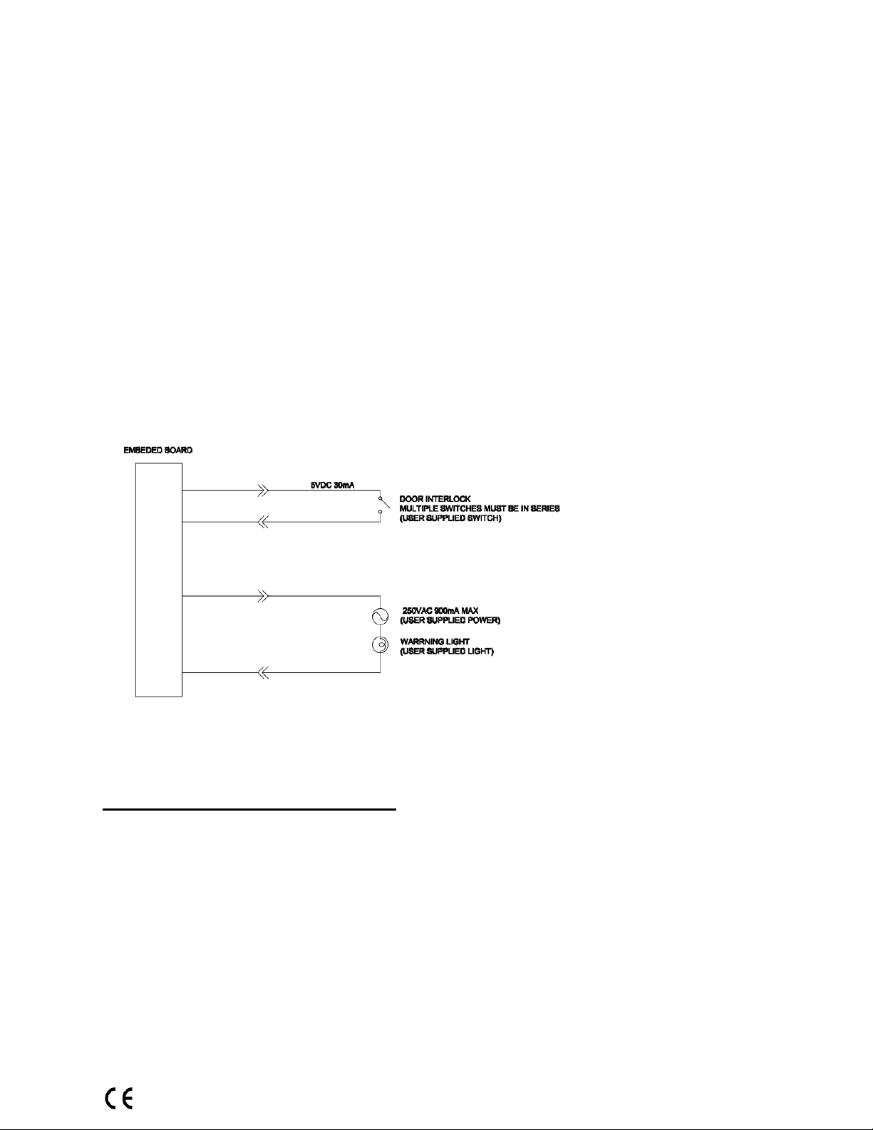
Warning System: The System is equipped with provisions for warning lights and/or audible
alarms when X-ray power is energized. An externally powered Warning System can be

6
0473 90001Rev07.26.13
connected to the cable provided which is capable of 250 volts, 50/60 hertz, and 1 amp. When X-
ray power is energized the warning system is also energized.
Interlock System: This System is equipped with provisions for an Interlock Circuit which, when
opened, will turn off X-ray power. This is a low voltage circuit, 5 volts DC. To use the Interlock
Circuit disconnect the factory installed Shorting Plug. Connect the supplied Interlock Cable to
the scanner. Connect door switches (NO/COM terminals) and/or emergency stop switches
(NC/COM terminals) in series between the other end of the Interlock Cable wires. Multiple door
switches and/or emergency stop switches can be connected as long as the devices are
connected in series. The entire circuit must be a closed loop when all of the doors are closed
and/or emergency stop switches are in their normally closed state.
Whenever the door switch or switches are opened or emergency stop button(s) pressed the X-
ray power will be turned off. X-ray power cannot be turned on when the interlock circuit is open.
Interlock and Warning System Schematic:
Patient Preparation Recommendations:
We recommend the patient wear FDA approved medical gloves for gripping the hand
rails, with sanitation and convenience in mind.
We also recommend the patient not step bare foot on the patient platform. Proper foot
protection should be provided.
After each patient scan, clean and disinfect all items which come in contact with the
patient.

7
0473 90001Rev07.26.13
Cabling Requirements:
System cabling connections must be installed away from walkways and doorways. It is
recommended to run cabling along wall perimeters. If there is a chance of mechanical damage
due to the cable location, then the use of conduit or other means of protection should be
considered.
Emergency Removal of a Patient:
The system has undergone extensive testing of the mechanically, electrically and software performance,
but if an unexpected occurrence is observed and/or the software locks up during a scan or
an
emergency arises where it becomes necessary to interrupt a scan and/or remove a patient from
the system before a scan is completed, please follow these steps:
1. Press the EMERGENCY STOP button. This will halt the X-ray as well as the motors
to the machine functions and all power to the machine. The message below will display
on screen and will terminate the “CB Scanning Device” Acquisition software:
2. Open the Gate doors manually with your hands by using the slots at the top of each
door to grasp and slide to an open position.
3. Carefully assist the patient to step out of the scan platform area.
4. Reset the machine: Close the PedCAT Acquisition, “CB Scanning Device” software
(if not already). Release the E-stop by turning the knob to the right until it pops up.
Then turn the machine power back ON at the Main Circuit Breaker. Re-launch the
PedCAT Acquisition “CB Scanning Device” software. Now the system can be operated
again as expected.

8
0473 90001Rev07.26.13
System Description
The PedCAT is a Computed Tomography X-ray system or Cone Beam Volumetric Tomography
x-ray system for 3D reconstruction Imaging device for the foot and ankle. The system is
designed for an in-office setting with components consisting of the Scanner, Operating
Computer (External Server), Operator’s Console and Viewing Console. The system provides
for patient’s to be imaged in weight bearing (standing) position as well as seated position for
one or both feet.
ViewingConsole
1. Viewingand
postprocessing
ofdata
OperatorConsole
1. Access,import,
andenterpatient
information
2. SelectScan
Options
3. InitiateAcquisition
ofImages
Machine
1. CaptureImages
2. TransferRawData
toExternalserver
ExternalServer
1. Reconstruct
Data
2. Storeand
BackupData
3. PostProcess
Data
QualityConsole
1. QAscan
results

9
0473 90001Rev07.26.13
The External Server consists of 4 Virtual Machines:
ACQ VM: accessed via the Main Desktop icon on the ACQ thin client terminal
Viewing Station/MD VM: accessed via the Main Desktop icon on the QCW thin client terminal
or the QA Station thin client terminal.
RECON VM: accessed via the Remote Desktop Connection icon on the ACQ thin client
terminal.
Database VM: accessed via the Remote Desktop Connection icon on the ACQ thin client
terminal.
Major Device Components:
PatientSupport
HandleBars
X‐RaySource
MainCircuitBreaker,rearof
machine
ImageDetector
Embedded
Controller
HV(X‐Ray)Power
Su
pp
l
y
PatientPlatform

10
0473 90001Rev07.26.13
Intended Use of the Device:
The PedCAT is intended to be used for 3-D imaging of the foot & ankle region, to visualize and
assess the osseous and certain soft tissue structures, including joint spaces, bone angles and
fractures. This modality is anticipated to be applicable to pediatric* cases as well as adults*,
when appropriate diagnosis of a given foot condition is considered necessary.
* Patient parameters: 50 lbs to 400 lbs
Groin area at least 22” above the floor
Major System Items:
Scanner
Dell server with hard drives, network cards, DVD drive, etc and Uninterrupted Power
Supply (UPS)
External Cable Kit
oDoor Interlock, 50’ (15.24 m)
oWarning System, 50’ (15.24 m)
oDoor interlock, shorting plug
oOperator Control Box Assembly, 50’ (15.24 m)
oExposure/Scan Switch Assembly, 10’ (3.05 m) coil cord
Ethernet Cable, CAT6, gray, 50’ (15.24 m) (QTY 2)
Ethernet cable, CAT 6, green, 50’ (15.24 m)
Ethernet cable, CAT6, red, 50’ (15.24 m)
Power cord, 10’ (3.05 m)
Varian Panel, 3030D
X-Ray tube assembly
HV power supply
About the Operators’ Manual:
This documentation describes the safe and effective operation of the system. The
information is intended to provide trained Technologists and Physicians the necessary
guidance to operate the system in a safe and effective manner.
CurveBeam assumes no liability for the use of this document if any unauthorized
changes to the content or format have been made.
Conventions Used in the User Manual:
Main Menu items and Tabs are in quotes (“ “). Software Programs are in quotes (“ “)
Interface buttons are capitalized” (BUTTON).

11
0473 90001Rev07.26.13
Standard Limited Warranty
CurveBeam, LLC warrants the original purchaser that this hardware system will be free from defects
for a period of one (1) year from the date of delivery. During the warranty period, CurbeBeam, LLC
will correct any defects in material or workmanship, at no charge for material, labor or travel. Any
replacement parts shall be new or serviceable used parts and are warranted for the remainder of the
original warranty or thirty (30) days, whichever is longer. The warranty period is not extended as a
result of purchasing any additional parts from CurveBeam, LLC. The original purchaser must promptly
notify CurveBeam, LLC in writing if there is a defect in material or workmanship. Written notice in all
events must be received by CurveBeam, LLC before expiration of the warranty period. This warranty
is not transferable. This One-Year Limited Warranty covers normal use.
CurveBeam, LLC does not warrant or cover the following:
• Damage caused by impact with other objects, dropping, falls, spilled liquids or immersion in liquids
• Damage caused by a disaster such as fire, flood, wind, earthquake, or lightning
• Damage caused by unauthorized attachments, alterations, modifications or foreign objects
• Damage caused by peripherals
• Damage caused by failure to provide a suitable environment
• Damage caused by the use of the hardware system for purposes other than those for which it was
designed
• Damage from improper maintenance
• Damage from improper electrical connection or supply
• Damage caused by any other abuse, misuse, mishandling, or misapplication
• Damage to internal or external computer, software, or operating system caused by;
Unauthorized additions or changes
Viruses, spyware, or gaming software
Damage caused by Network or Operating Engineers
Damage from the use of this machine or computer for any other purposes.
Applications other than its intended use
Damage caused by third party software or damage caused by unauthorized changes to the
system software
Damage caused by unauthorized upgrades, additions or deletions or damage caused by
internet use, or any other unauthorized application. Under no circumstances shall
CurveBeam, LLC be liable for any special, incidental, or consequential damages based upon
breach of warranty, breach of contract, negligence, strict liability or any other legal theory.
Such damages include, but are not limited to, loss of data, loss of profits, loss of revenue, loss
of use of hardware system or any associated equipment, cost of capital, cost of substitute or
replacement equipment, facilities or services, down time, purchaser's time, the claims of third
party, including customers, and injury to property.
Disclaimer of Warranties The warranty stated above is the only warranty applicable to this product,
all other warranties, expressed or implied including all implied warranties of merchantability or fitness
for a particular purpose, are hereby dis-claimed. No oral or written information or advice given by
CurveBeam, LLC, its agents or employees shall create a warranty or in any way increase the scope of
this warranty.

12
0473 90001Rev07.26.13
CHAPTER 2: Product Information
Technical Specifications:
DescriptionSpecification
Tubevoltage100‐120kVp
Tubecurrent3‐5mA
CBCTScantime*16‐32sec
CBCTProceduretime**19‐68sec
Maxexposuretime9sec
ImagedetectorAmorphousSiliconflatpanel
Grayscale14bit
CBCTImagingVolume7.9”(20cm)highx13.8”(35cm)diameter,
7.9”(20cm)highx7.9”(20cm)diameter
Typicalresolution0.3mmvoxel,0.35mmvoxel
Measurementaccuracy±2voxel
BodypartscannedFootandankle
Sizeofsystem:hxdxw47”x59”x48”(119.4cmx149.9cmx121.9cm)
Weight400lbs(181.8kg)
PowerRequirements1150VA
*Scan time is defined as the duration in which the exposure alarm (buzzer) is ON and X-ray ON
light is illuminated.
**Procedure time is included Scan time plus filament warm up, doors opening, etc.
X-ray Source:
Tube Voltage: 100-120 kVp(eff)
Tube Current: 3-5 mA
Voltage Wave Shape: Constant Potential
Focal Spot: 0.0197 inches (0.5 mm)
Duty Cycle: 3%
Source to Sensor distance: 28.896” (73.39 cm)
Source to Patient distance: 21.095” (53.58 cm*)
*The patient must be properly positioned for each patient for all applications in
order to have the focal spot to skin distance as large as possible.
Minimum Filtration (at 120 kVp(eff)) (mm of aluminum equivalent): 10 mm or greater
Maximum Rated Continuous Tube Operation: 130 kVp @ 0.5 mA
Maximum Rated Pulsed Tube Operation: 130 kVp @ 5mA

13
0473 90001Rev07.26.13
NOTE: Leakage technique factors are measured at the maximum specified energy.
Maximum Deviation: kV: ± 5 kV
mA: ± 10%
Timer: ± 0.1 seconds or 5%, whichever is greater
Maximum Excursion: 15 kV at 120 kV
X-ray Beam Size: 2 Rectangular: 11.8” (30 cm) wide x 11.8” (30 cm) high, 5.9” (15 cm)
wide x 5.9” (15 cm) high
Image Detector: Amorphous Silicon Flat Panel (readable area): 11.8” (30 cm) height x
11.8” (30 cm) width.
Sensor Front Panel Attenuation Value: Less than 1mm of aluminum equivalent
(information for reference only)
Gray Scale: 14 bit
Voxel Size: 0.3/0.35
CBCT Image Acquisition: 1 or 2 orbits, 360 degree rotation (maximum)
CBCT Field of View: 7.9” (20 cm) diameter x 7.9” (20 cm) height (1/2 or 1 orbit)
CBCT Extended Field of View: (offset scan): 13.8” (35 cm) diameter x 7.9” (20 cm)
height (2 orbits)
CBCT Procedure Times: 19 sec for 20 x 20, 68 sec for 35 x 20

14
0473 90001Rev07.26.13
Patient Procedure options available for scanning:
Patient Parameters Procedure
Exposure Factors Procedure Type
Small Size:
Weight: 50 to 100 lbs (23-45 kg),
Height: G
roin area at least 22” (56
cm) above the floor.
100 kVp, 5mA Small Patient:
Medium Field
(100kVp)
Small Size:
Weight: 50 to 100 lbs (23-45kg),
Height: G
roin area at least 22” (56
cm) above the floor.
100 kVp, 5mA Small Patient:
Large Field
(100kVp)
Weight: 101 to 400 lbs (46-181 kg),
Height: G
roin area at least 22” (56
cm) above the floor.
120 kVp, 5mA Large Field
(120kVp)
Weight: 101 to 400 lbs (46-181 kg),
Height: G
roin area at least 22” (56
cm) above the floor.
120 kVp, 5mA Medium Field
(120kVp)
Weight: 101 to 400 lbs (46-181 kg),
Height: G
roin area at least 22” (56
cm) above the floor.
120 kVp, 5mA Medium Field,
Sharp Filter
(120kVp)

15
0473 90001Rev07.26.13
Minimum patient size parameters:
CBCT Primary Reconstruction: Maximum of 5 minutes
CBCT Secondary Reconstruction: Real Time
Gantry Stopping Distance and Angle: Total rotation from Home position to limit is 424
degrees (Home being 0 degrees). “Load” position (gantry aligned for patient to walk in)
is 25 degrees from home position.
X
-ra
y
beam

16
0473 90001Rev07.26.13
Power Requirements:
The Scanner requires a Dedicated Line and/or Filtered Line. A Surge Protector is
recommended. The Scanner is suitable for continuous connection to a power supply in stand-by
mode.
Line Voltage: 100VAC, 115VAC, 200VAC or 230VAC (Factory Set)
Line Voltage Regulation requirement: ± 10%
Line Current: 10 Amps (100V), 10 Amps (115V), 5 Amps (200V) or 5 Amps (230V)
Line Frequency: 50 Hz / 60 Hz
Phase: Single
Main Circuit Breaker: 10 Amps (100V), 10 Amps (115V), 5 Amps (200V), or 5 Amps
(230V)
Nominal Electrical Input Power to Supply: Volume Scan = 300W (120kV, 5mA); Scan
Time has no effect on electrical power output.
Apparent Resistance of Supply Mains:
For the purpose of obtaining the apparent resistance of supply mains, resistance is determined
according to the following formula:
R= UO – U1
I1
Where:
U0 is the no-load Mains Voltage
U1 is the Mains Voltage under load.
I1 is the Mains Current under load.
CircuitBreaker
Assembly
UOUII1Apparent
Resistance
100VAC
100VAC98.8VAC2.5A0.48ohms
115VAC115.4VAC114.2VAC2.1A0.57ohms
200VAC200.4VAC198.1VAC1.3A1.77ohms
230VAC230.8VAC228.0VAC1.2A2.33ohms

17
0473 90001Rev07.26.13
Environmental Specifications:
Operating:
The operational temperature range shall be 59°F to 86°F (+15°C to +30°C).
The operational humidity range shall be 25 to 60% relative humidity, non-
condensing.
The minimum time period that the room environmental operating conditions must be
maintained prior to powering the system is 1 hour.
Transportation and Storage:
The storage and transport temperature range shall be -4°F to 122°F (-20°C to
+50°C).
The storage & transport humidity range shall be 10% to 95% relative humidity, non-
condensing.
Scanner and Acquisition Computer (server):
Requires a Dedicated Line and a Surge Protector is recommended.
Patient Platform:
Maximum patient weight capacity: 400 lbs. (181kg)
Patient Seat:
Maximum patient weight capacity: 300 lbs. (136kg)
Handle Bars:
Maximum weight capacity: 150 lbs. (68kg)
Disposal:
Follow local regulations on disposal of waste parts. The X-ray source assembly, image
sensor and all electronic circuits should be regarded as non environmental friendly
waste product. The system does not generate, or require the use of, any materials that
require special disposal instructions as part of regular operation.
Extension Cords:
Do not use any extension cords which are not provided with the system. Be aware that
multiple portable socket outlets or extension cords are not to be connected to the
system.
External Items:
Do not connect any items or equipment to this system which are not part of the system.

18
0473 90001Rev07.26.13
Electromagnetic or other Interference (Emissions and Immunity):
The system was tested and it was determined to meet the class A (non-residential)
limits. The system
pass testing with a reduced level of compliance
with the criteria
contained in IEC 60601-1-2 Edition 3 Issued 03/2007.
Test Name Test Level/
Equipment Class Results/Notes Immunity
Performance
Criteria Met
Emissions Testing
Radiated Emissions Class A: Group 1 Compliant -
Conducted Voltage Emissions Class A: Group 1 Compliant -
IEC61000-3-2 Harmonic Current
Emissions
Class A Compliant -
IEC61000-3-3 Voltage Changes,
Voltage Fluctuations and Flicker
Class A Compliant -
Immunity Testing
61000-4-2 Electrostatic Discharge ±6 kV Contact, ±8 kV
Air
Compliant A
61000-4-3 Radiated Immunity 80 MHz – 2.5 GHZ,
3 V/M, 80% AM with
1kHz
Compliant A
61000-4-4 Electrical Fast
Transients
±1 kV Power Supply
Lines, ±1 kV
Input/Output Lines
Reduced Level of
Compliance
A
61000-4-5 Surge Immunity ±1 kV Line to Line,
±2 kV Line to Earth
Compliant A
61000-4-6 Conducted Immunity 150 kHz – 80MHz,
3 Vrms
Compliant A
61000-4-8 Power Frequency
Magnetic Field
3 A/M Compliant A
61000-4-11 Voltage Dips and
Short Interruptions
˃95% dip for 0.5
periods
Compliant A
60% dip for 5 periods Compliant A
30% dip for 25 periods Compliant A
˃95% dip for 5 seconds Compliant C

19
0473 90001Rev07.26.13
WARNING This system is intended for use by healthcare professionals only. This system
may cause radio interference or may disrupt the operation of nearby equipment. Follow the
following recommendations below.
Recommended separation distances between portable and mobile RF
communications equipment and the PedCAT
The PedCAT is intended for use in an electromagnetic environment in which radiated RF
disturbances are controlled. The customer or the user of the PedCAT can help prevent
electromagnetic interference by maintaining a minimum distance of 10 feet (3 m)
between portable and mobile RF communications equipment (transmitters) and the
PedCAT. Refer to the portable and mobile RF communications equipment user’s manual
for recommended clearance distances to other equipment based on the maximum
output power of the communications equipment. Maintain a minimum distance of 10 feet
(3m) between the PedCAT and portable and mobile RF communication equipment.
Equipment Standards:
The PedCAT has been designed and evaluated to meet the requirements of the following
standards. The device has passed all applicable sections of these standards.
IEC 60601-1, third edition, 12/2005 IEC 60601-1, second edition, 12/1995
IEC 60601-1-2, third edition, 03/2007
IEC 60601-1-3, second edition, 01/2008 IEC 60601-1-3, first edition, 01/1994
IEC 60601-1-6, third edition, 01/2010 IEC 60601-1-6, first edition, 01/2006
IEC 60601-1-8, second edition, 10/2006 IEC 60601-1-8, first edition, 1/2003
IEC 60601-2-7, second edition, 02/1998
IEC 60601-2-44, third edition, 02/2009 IEC 60601-2-44, second edition, 01/2002
IEC 62304, first edition, 05/2006
ISO 15223-1:2012
ANSI/AAMI ES60601-1, third edition, 01/2005
CSA C22.2 NO. 60601-1:08-CAN/CSA, third
edition, 07/2008
BS EN ISO 14971:2009
EN ISO 15223-1:2012
BS EN 1041:2008
The PedCAT conforms to the provisions of MDD 93/42/EEC (as transposed into national law in
the United Kingdom through Statutory instrument SI 618 2002 Medical Device Regulations 2002
and as amended by SI 2008 No. 2936).and Australian Medical Device Directives, TGA , v1.1,
May, 2011
Table of contents
Popular Medical Equipment manuals by other brands

Schiller
Schiller FRED easyport plus user guide

FaceLake
FaceLake JPD-100B instruction manual

MEDICAL ILLUMINATION
MEDICAL ILLUMINATION CENTURION EXCEL Installation and service manual

KLS Martin group
KLS Martin group marLED E3 Service manual

OPTIKON
OPTIKON KERATRON SCOUT Installation and operating manual

ERKA.
ERKA. ERKAMETER 125 PRO user manual