6. System Operation
XR 3500/3700
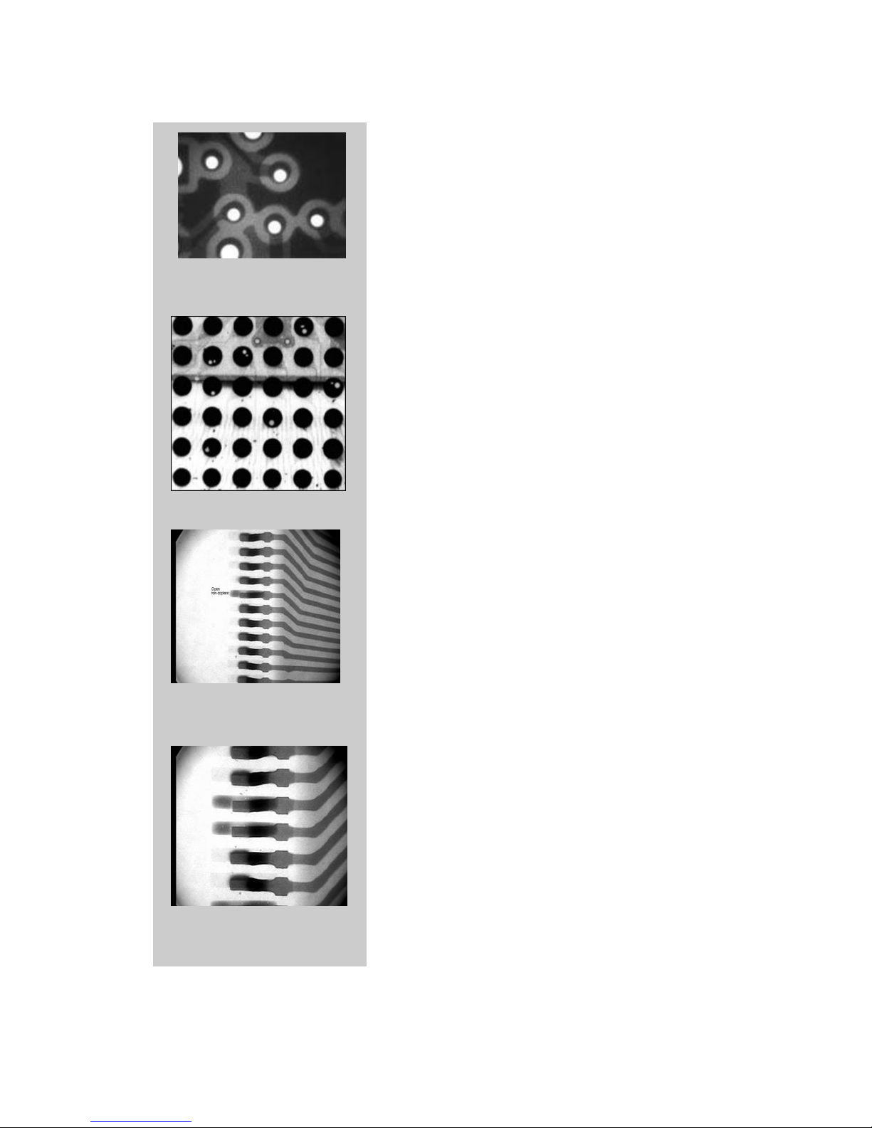
Bare Board
Hole/Pad Offset
BGA Voiding
Leaded Component
Non-Co planarity
Leaded Component
Opens
The XR 3500/3700 Real Time Inspection System is a
powerful tool in the quality control and process verification
of all aspects of microelectronics manufacturing. The XR
3500/3700 provides rapid, real-time x-ray inspection for
production and rework environments. Its self-contained
console design supports easy customizing for numerous
applications, including multi-layer PCBs, small hole
drilling, large back-planes and assemblies with advanced
components, such as BGAs, BGAs and chip-scale
packages.
In bare board applications, it can be used to check for
interlayer shift and drilled hole-to-pad offset. Inspection is
performed following lamination, to determine the
presence and degree of interlayer shifts. At the onset of
either conventional or small hole drilling, inspection is
used to qualify hole-to-pad alignment. In addition to
enhancing product quality, x-ray inspection enables users
to control costs by eliminating defective boards early in
the production process. It can also be used to quality
control incoming boards from vendors or customers so
that defects can be detected before problems occur.
For surface mount components, it is used to verify
lead/pad coplanarity, shorts, opens, and solder bond
quality. It can be used to check resistors and capacitors
as well as IC’s for internal damage and verify adjustments
throughout the placement and reflow processes.
For BGA’s, the XR 3500/3700 can be used to check for
all potential defects including: shorts, opens, mis-
registration, non-wetting, solder ball voids, and
delamination. X-ray is used to verify proper reflow
profiles for advanced packages, and to control rework
process.