CUSTOM ULTRASONICS Scope-Assist Flushing Sink Installation instructions

MAN-100 Revision 03082022 Page 1 of 22
Scope-Assist Flushing Sink
Operator’s and Maintenance Manual
Table of Contents
1GENERAL INFORMATION ....................................................................................................3
ABBREVIATIONS ................................................................................................................................................3
WARNING/CAUTION STATEMENTS......................................................................................................................3
Warnings .................................................................................................................................................3
Cautions ..................................................................................................................................................4
INDICATIONS FOR USE/INTENDED USE ...............................................................................................................4
PRODUCT DESCRIPTION.................................................................................................................................... 4
Configurations .........................................................................................................................................5
Operating Principle.................................................................................................................................. 5
Physical Characteristics .......................................................................................................................... 5
Interfaces.................................................................................................................................................5
Assembly.................................................................................................................................................6
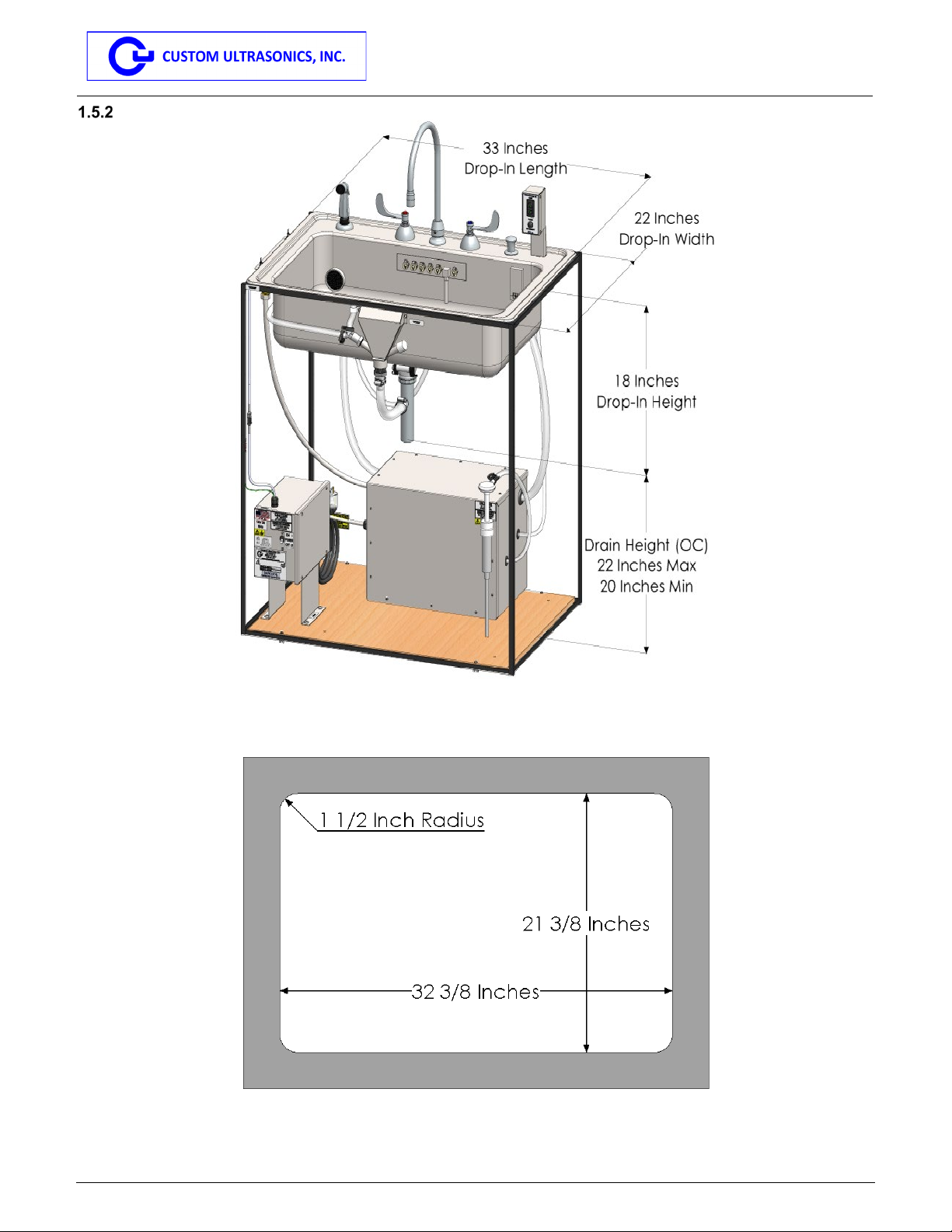
DIMENSIONS AND COMPONENTS........................................................................................................................6
Model S6 Dimensions .............................................................................................................................6
Model S8 Dimensions .............................................................................................................................7
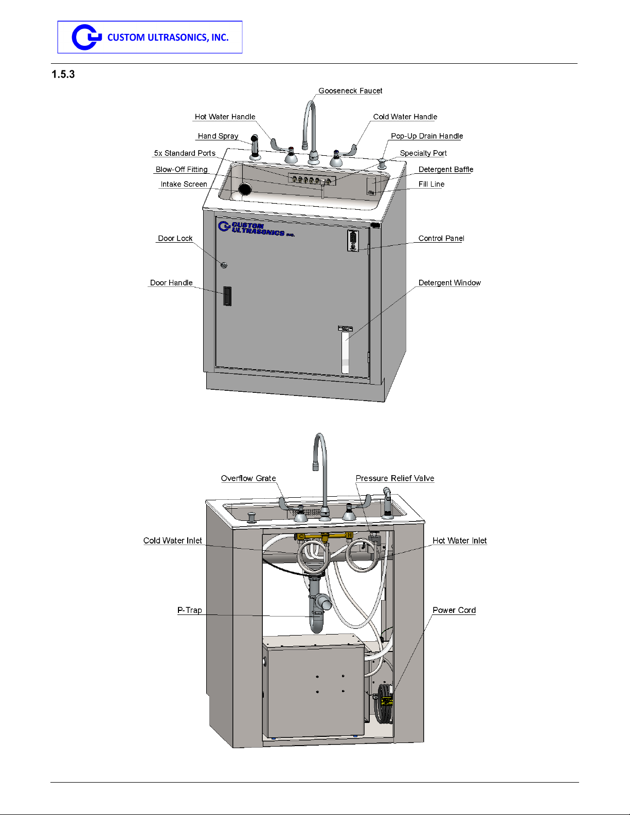
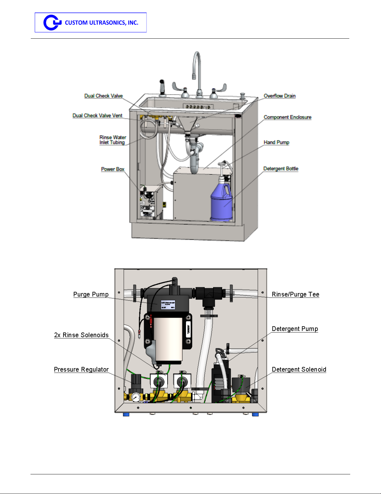
Component Diagrams .............................................................................................................................8
2INSTALLATION ...................................................................................................................10
MODEL S8 INSTALLATION ................................................................................................................................10
Model S8 Installation .............................................................................................................................10
WATER SUPPLY REQUIREMENTS .....................................................................................................................10
Water Supply Installation ......................................................................................................................11
WASTE DRAIN REQUIREMENTS........................................................................................................................11
Waste Drain Installation ........................................................................................................................11
ELECTRICAL SUPPLY REQUIREMENTS ..............................................................................................................11
Electrical Supply Installation .................................................................................................................11
DETERGENT BOTTLE CONNECTION ..................................................................................................................11
Detergent Bottle Installation ..................................................................................................................11
3POST-INSTALLATION INSPECTION..................................................................................12
WATER INLET SYSTEM ....................................................................................................................................12
DRAINAGE SYSTEM .........................................................................................................................................12
DETERGENT SYSTEM ......................................................................................................................................12
PURGE SYSTEM..............................................................................................................................................12
RINSE SYSTEM ...............................................................................................................................................12
4OPERATING INSTRUCTIONS.............................................................................................13
CAUTIONS ......................................................................................................................................................13
OPERATING THE SAFS ...................................................................................................................................13
Performing the Leak Test......................................................................................................................13
Filling the Sink Basin .............................................................................................................................13
Brushing/Wiping the Endoscope Channels...........................................................................................13
Connecting an Endoscope to the SAFS ...............................................................................................13
Flushing Channels with Detergent Solution ..........................................................................................14
Drain the Detergent Solution.................................................................................................................14
Rinsing Channels with Clean Rinse Water ...........................................................................................14
Draining the Rinse Water ......................................................................................................................14
Rinsing the Endoscope Exterior and Sink Basin...................................................................................14
5MAINTENANCE ...................................................................................................................15
DAILY MAINTENANCE ......................................................................................................................................15
Operator’s Daily Checklist.....................................................................................................................15
Daily Cleaning and Decontamination ....................................................................................................15
QUARTERLY MAINTENANCE AND INSPECTION ...................................................................................................16
Visual Inspection ...................................................................................................................................16
Intake Screen Inspection.......................................................................................................................16
Adapters and Channel Flushing Port Inspection...................................................................................16
Solenoid Inspection ...............................................................................................................................16

MAN-100 Revision 03082022 Page 2 of 22
Scope-Assist Flushing Sink
Operator’s and Maintenance Manual
Detergent Pump Poppet Valves............................................................................................................18
Overflow Drain.......................................................................................................................................19
Detergent Function................................................................................................................................19
Purge Function ......................................................................................................................................19
Rinse Function ......................................................................................................................................19
Water Pressure Regulator.....................................................................................................................19
ANNUAL MAINTENANCE AND INSPECTION .........................................................................................................20
Replace Female Quick-Disconnect Fittings ..........................................................................................20
MAINTENANCE SCHEDULE ...............................................................................................................................20
6PART ORDERS....................................................................................................................20
7CONTACT INFORMATION ..................................................................................................21
ATTACHMENTS:
DISC FILTER REPLACEMENT LOG.......................................................................................A-1

MAN-100 Revision 03082022 Page 3 of 22
Scope-Assist Flushing Sink
Operator’s and Maintenance Manual
1 General Information
To obtain the Operator’s Manual and other product information, please go to the Custom Ultrasonics website:
www.customultrasonics.com. Once you are registered, a copy of the manual, and if applicable, other product
information can be download under the Product Documentation field. Adobe PDF reader is required to open and
view the document.
For users new to the website select the My Profile tab to login. Select the Register button under New Users.
Complete the required field and press the Register button. Authorized user will then be provided with a registration
confirmation email.
Abbreviations
•ASP:Authorized Service Provider
•CUI: Custom Ultrasonics, Inc.
•OEM: Original Equipment Manufacturer
•PSI: Pounds Per Square Inch
•SAFS: Scope-Assist Flushing Sink
•UDI: Unique Device Identifier
Warning/Caution Statements
A warning is a statement that alerts the user to the possibility of injury, death or other serious adverse reactions
associated with the use or misuse of the device.
A CAUTION indicates a potentially hazardous situation which, if not avoided, may result in minor or moderate injury.
It may also be used to alert against unsafe practices or potential equipment damage. Such problems include:
malfunction, failure, and damage to the Scope-Assist Flushing Sink or damage to other property. The caution
statement includes the cautions that should be taken to avoid the hazard.
Warnings
•The Scope-Assist Flushing Sink must be turned off and unplugged before performing any service or
maintenance. Failure to do so may result in electric shock.
•The Scope-Assist Flushing Sink is not intended to nor does it solely provide cleaning or disinfection for any
endoscope processed.
•Use only endoscope adapters approved by Custom Ultrasonics.
•The Scope-Assist Flushing Sink is not designed to replace the manual flushing of the elevator recess of side-
viewing endoscopes with a syringe as specified by the endoscope manufacturer’s instructions.
•Endoscopes that have an elevator mechanism require additional manual cleaning per endoscope
manufacturer’s instructions.The operator must pay special attention during manual cleaning to adhere to
these instructions.
•Use of the Scope-Assist Flushing Sink adjacent to or stacked with other equipment should be avoided as it
could result in improper operation. If such use is necessary, this equipment and the other equipment should
be observed to verify that they are operating normally and as intended.
•Use of accessories, transducers, and cables other than those specified/provided by Custom Ultrasonics could
result in increased electromagnetic emissions or decreased electromagnetic immunity of the Scope-Assist
Flushing Sink and result in improper operation.
•Portable radio-frequency communications equipment (including peripherals such as antenna cables and
external antennas) should be used no closer than 12 inches (30 cm) to any part of the Scope-Assist Flushing
Sink, including cables specified by Custom Ultrasonics. Otherwise, degradation of the performance of this
equipment could result.
•The Scope-Assist Flushing Sink must NOT be located next to or near an X-Ray, CAT scan, MRI equipment,
or any other major sources of electromagnetic interference.
•The main performance of the Scope-Assist Flushing Sink has been determined to be its capability in
dispensing detergent, purging the channels, and rinsing water through the channels of an endoscope.
•If the Scope-Assist Flushing Sink is subjected to electromagnetic disturbances beyond the tested immunity
capabilities, performance may be adversely affected. If such disturbances are experienced and cause a drop
in the quality of performance, the operator should perform detergent, purge, and rinse functions again after
the disturbance has subsided.If the disturbance persists, Custom Ultrasonics should be contacted.

MAN-100 Revision 03082022 Page 4 of 22
Scope-Assist Flushing Sink
Operator’s and Maintenance Manual
Cautions
•Always follow the facility policies and procedures regarding use of personal protective equipment (face mask,
gown, gloves, etc.) when handling soiled endoscopes.
•Pulling forward or pushing back on the drain handle may cause damage. Only pull straight up and push
straight down.
•Service is only to be performed by a Custom Ultrasonics Authorized Service Provider (ASP).
•Never overload or leave the Scope-Assist Flushing Sink unattended while filling.
•Make sure the overflow plenum drain line is clear before use. The built-in overflow plenum directs water to
the drain line thereby reducing the potential for overflow.
•Always be certain that the purge/rinse functions are turned off prior to disconnecting adapters or lifting
endoscopes out of the basin.
•Failure to attach and secure all adapters may result in flushing operation failure.
•Visually confirm liquid flow through the transparent adapter tubing during flushing of endoscope’s internal
channels. No flow is an indication that there may be a blockage in the Scope-Assist Flushing Sink or within
the endoscope channel. If a blockage in the Scope-Assist Flushing Sink occurs, discontinue use and contact
Custom Ultrasonics for diagnostics and/or repair. If an endoscope channel is blocked, do not proceed;
contact the endoscope manufacturer.
•Ensure the adapters have not become disconnected from the manifold or endoscope prior to removing the
endoscope from the Scope-Assist Flushing Sink. If one or more of the adapters became disconnected,
repeat the flushing process.
•When replacing the detergent bottle and priming the detergent injection line, do not press the detergent bottle
hand pump until the detergent injection switch is engaged; damage to the detergent pump or detergent
plumbing may occur if the bottle is pumped while the detergent system is off.
•Failure to maintain proper maintenance may cause fluid overflow which may create a slip hazard and/or
create water damage.
•Endoscopes, including duodenoscopes, should be inspected and maintained as per the endoscope
manufacturer’s labeling requirements.
•When using adapters provided by the endoscope manufacturer, please check the CUI endoscope adaptation
chart and diagrams at customultrasonics.com.
•When performing leak testing in the Scope-Assist Flushing Sink, follow the endoscope manufacturer’s
instructions. If leak testing fails, contact the endoscope manufacturer.
•Dispose of all packaging materials, and the temporary storage cart for the model S8, in accordance with
facility, local, and state waste disposal regulations.
•Only Custom Ultrasonics OEM components have been validated in the Scope-Assist Flushing Sink, therefore
use only OEM components to ensure proper performance and compliance with tested standards.
•Refer to the Endoscope Flushing Matrix on customultrasonics.com for endoscope model flushing
requirements.
Note: In the event that flow is restricted in an adapter featuring a disc filter (P/N 16030), the operator is
instructed to replace the disc filter, irrespective of its in-use time, and confirm restored flow through
the adapter. If no flow is observed through the adapter, stop using the sink and call Custom
Ultrasonics for service.
Indications for Use/Intended Use
The Scope-Assist Flushing Sink is intended for flushing the channels of flexible endoscopes according to the
endoscope manufacturer’s instructions.
Warning: The Scope-Assist Flushing Sink is not intended to nor does it solely provide cleaning or disinfection for
any endoscope processed. Use only the adapters approved by Custom Ultrasonics.
Product Description
The Scope-Assist Flushing Sink is designed to mechanically assist the channel flushing portion of an endoscope’s
manual cleaning process. The sink facilitates compliance with endoscope manufacturer’s cleaning requirements by:
•Providing a means of flushing flexible endoscope channels with detergent solution
•Providing a means of flushing endoscope channels with water
•Providing an environment for soaking and manual wiping/brushing of flexible endoscope exterior surfaces
and accessories

MAN-100 Revision 03082022 Page 5 of 22
Scope-Assist Flushing Sink
Operator’s and Maintenance Manual
•Providing an environment to perform wet leak testing of endoscopes
The Scope-Assist Flushing Sink is designed:
•To be used where the facility performs its endoscope cleaning functions, such as in soiled utility rooms,
central processing decontamination areas, or endoscope cleaning (reprocessing) areas
•To be used with Tergal®800 Detergent
The Scope-Assist Flushing Sink is not designed:
•To be used at bedside, in critical care units, or in sterile environments
•To be used as a terminal process or as part of the manual high level disinfection process
Note: The Scope-Assist Flushing Sink has been validated for use with Tergal®800 Detergent. The device is
factory preset for dosing and delivery of Tergal®800 Detergent.
Warning: The Scope-Assist Flushing Sink is not designed to replace the manual flushing of the elevator recess of
side-viewing endoscopes with a syringe as specified by the endoscope manufacturer’s instructions.
Warning: Endoscopes that have an elevator mechanism require additional manual cleaning per endoscope
manufacturer’s instructions. The operator must pay special attention during manual cleaning to adhere
to these instructions.
Configurations
The Scope-Assist Flushing Sink is available in two models: the Model S6 is housed in a cabinet and is designed to
be hard plumbed and fixed in place; the Model S8 has no cabinet and is designed to be installed directly into a fixed
base cabinet with countertop or casework provided by the end user facility.
Operating Principle
The Scope-Assist Flushing Sink is a self-contained, semi-automated, manually operated, electro-mechanical
endoscope flushing sink that utilizes potable tap water and a system of pumps and solenoids to create the conditions
necessary to immerse and flush an endoscope in a detergent solution and to rinse the endoscope with potable tap
water.
Physical Characteristics
The Scope-Assist Flushing Sink consists of a stainless steel sink basin with a swinging gooseneck faucet, hot and
cold water inlet valves, and a hand spray. Advanced features include a liquid detergent injection system and a
manifold with quick-disconnect endoscope channel flushing ports.
The Model S6 is housed in a stainless steel cabinet with a standard water inlet, drain line plumbing, electrical
connections, and is shipped prepared to be permanently fixed in place.The Model S8 does not have a cabinet and
can be installed into a fixed base cabinet with countertop or casework system using its standard water inlet drain line
plumbing, and electrical connections. Both models are composed of UL listed and/or recognized electrical
components, as well as standard and/or medical grade metals, rubbers, and plastic polymers.
Interfaces
The Scope-Assist Flushing Sink’s primary users are medical technicians, nurses, and other trained health care
personnel. User interfaces include plumbing fixtures, a control panel with LED indicators, a circuit breaker, and a
manifold with quick-disconnect endoscope channel flushing ports. The environmental interface consists of a 120
VAC, 2 AMP, 60 Hz power source connection, a primary hot and cold potable tap water source connection, a
secondary cold potable tap water connection, and a connection to a primary drain within the facilities’ plumbing
system. The Scope-Assist Flushing Sink is not a required accessory to any medical device or equipment and it does
not come into contact with a patient at any time during use. In addition to the flushing of the endoscope channels,
the Scope-Assist Flushing Sink plays a passive role in the processing of endoscopes by providing an environment
where an endoscope can be leak tested, have its exterior surfaces manually wiped down, and have its connection
ports and channels brushed.

MAN-100 Revision 03082022 Page 6 of 22
Scope-Assist Flushing Sink
Operator’s and Maintenance Manual
Assembly
The Scope-Assist Flushing Sink is assembled in the United States in compliance with the Quality System Regulations
per 21 CFR 820 requirements and it is manufactured by Custom Ultrasonics, Inc. at 144 Railroad Drive, Ivyland, PA,
18974. Custom Ultrasonics, Inc. is an FDA registered and ISO 13485 certified medical device manufacturing
company.
Dimensions and Components
Model S6 Dimensions
Fig. 1.5.1-1 SAFS Model S6 Dimensions – Front
Fig. 1.5.1-2 SAFS Model S6 Dimensions – Side

MAN-100 Revision 03082022 Page 7 of 22
Scope-Assist Flushing Sink
Operator’s and Maintenance Manual
Model S8 Dimensions
Fig. 1.5.2-1 SAFS Model S8 Dimensions
Fig. 1.5.2-2 SAFS Model S8 Countertop Cut-Out Dimensions

MAN-100 Revision 03082022 Page 8 of 22
Scope-Assist Flushing Sink
Operator’s and Maintenance Manual
Component Diagrams
Fig. 1.5.3-1 SAFS Components – Front (note: the SAFS Model S6 is shown)
Fig. 1.5.3-2 SAFS Components – Back (note: the SAFS Model S6 is shown)

MAN-100 Revision 03082022 Page 9 of 22
Scope-Assist Flushing Sink
Operator’s and Maintenance Manual
Fig. 1.5.3-3 SAFS Components – Inside (note: the SAFS Model S6 is shown)
Fig. 1.5.3-4 SAFS Components – Component Enclosure

MAN-100 Revision 03082022 Page 10 of 22
Scope-Assist Flushing Sink
Operator’s and Maintenance Manual
2 Installation
If you would like to have a Custom Ultrasonics field technician or authorized service technician conduct the final post
installation inspection and/or on-site training or post installation inspection only for the Scope-Assist Flushing Sink,
contact Custom Ultrasonics at customultrasonics.com or email Service@customultrasonics.com. Custom
Ultrasonics personnel cannot install a fixed base cabinet and countertop or casework system for a Model S8 and
cannot complete facility plumbing prior to final post installation inspection of the SAFS. It is the customer’s
responsibility to meet the installation requirements prior to the final post installation inspection of the SAFS.
Check for visible damage prior to and during unpacking of the SAFS.If visible damage is evident upon receipt,
immediately contact Custom Ultrasonics.
Refer to step 2.1 for initial installation of a Model S8 SAFS. Refer to steps 2.2 – 2.5 for final installation of the SAFS
Model S6 and SAFS Model S8. Refer to the diagrams in Section 1.5.3 for a view of SAFS components and their
positions within the device.
Caution: Installation of the SAFS must be performed in accordance with Custom Ultrasonics installation
requirements. Refer to the SAFS Site Requirements (SR-SAFS-001) for installation requirements.
Installation must also follow all state and local code requirements.
Note: The emissions characteristics of this equipment make it suitable for use in industrial areas and hospitals
(CISPR 11 class A). If it is used in a residential environment (for which CISPR 11 class B is normally required)
this equipment might not offer adequate protection to radio frequency communications services. The user
might need to take mitigation measures, such as relocating or re-orienting the equipment.
Model S8 Installation
Prior to installing the SAFS Model S8, components must first be removed from the temporary storage cart.
Note: Installation of the SAFS Model S8 should be conducted by at least two people.
Model S8 Installation
On the countertop surface of the cabinet that will house the SAFS Model S8, cut out an area for sink basin
placement as defined in Figure 1.5.2-2.
Disconnect the purge inlet, manifold inlet, and detergent inlet tubing from the back of the sink basin.
Disconnect the control panel wire harness and sink basin ground wire from the sink basin.
Lift the sink basin from the temporary storage cart and place it into the cut-out on the countertop.
Secure the sink basin to the countertop with the sink basin mounting clips that are packaged with the SAFS.
Remove the Backflow Preventer from the cart and secure it to the underside of the cabinet countertop.
Run the outlet PVC tubing of the backflow preventer to the overflow plenum on the front of the sink basin.
Remove the cover from the component enclosure and unscrew the component enclosure from the plywood
base of the temporary storage cart.
Unscrew the power box from the plywood base of the temporary storage cart
Secure both the power box and component enclosure inside the cabinet using the appropriate hardware for
the substrate (not supplied).
Connect the stainless steel hose from the inlet of the rinse solenoids inside the component enclosure to the
backflow preventer outlet.
Connect the sink basin purge inlet to the purge inlet tubing from the left of the component enclosure.
Connect the sink basin manifold inlet to the manifold inlet tubing from the right of the component enclosure.
Connect the sink basin detergent inlet to the detergent inlet tubing from the right of the component enclosure.
Reconnect the control panel wire harness and sink basin ground wire.
Reattach the component enclosure cover.
Water Supply Requirements
•Plumbing configurations must follow state and local codes.
•NSF/ANSI-61 or NSF-PW certified minimum ½” copper, PVC, CPVC, etc. water supply lines.
•Water pressure must be between 40 and 60 PSI.
•Water hardness must be less than 120 ppm or 7 gpg (CaCO3)

MAN-100 Revision 03082022 Page 11 of 22
Scope-Assist Flushing Sink
Operator’s and Maintenance Manual
•The Faucet requires 1 hot and 1 cold supply line terminating with ⅜” compression shut-off valves.
•The Cold Water Rinse Line requires 1 cold supply with a reduced pressure zone backflow preventer
terminating with a ⅜” compression shut-off valve.
Warning: Back pressure may occur on the fresh water rinse line of the SAFS during operation. The
reduced pressure backflow preventer must be installed in an accessible location to facilitate
testing and service. An air gap fitting is required when a reduced pressure backflow preventer
is installed.A discharge line should be piped from the air gap at the relief valve connection
making sure there is adequate drainage.
Water Supply Installation
Attach incoming hot and cold water supply lines to the SAFS with the supplied braided hoses from the faucet.
Ensure hot supply is connected to the hot valve and cold supply is connected to the cold valve.
Attach the fresh water rinse line to the braided hose from the dual check valve.
Waste Drain Requirements
•A drain system with a minimum 1½” standard connection that is less than 22” above the floor.
•SAFS Model S6: Connection must be between 18” and 22” on center (OC) above the floor.
•SAFS Model S8: Connection must be between 20” and 22” on center (OC) above the floor.
Waste Drain Installation
Connect the P-trap to the tailpiece of the drain line.
Attach the P-trap to a 1½” (minimum) drain line.
Electrical Supply Requirements
•A 120 VAC (±10%), single phase, 60Hz, 15A circuit.
•A NEMA 5-15R, GFCI, protected outlet located within the operator’s reach.
Electrical Supply Installation
Verify the SAFS circuit breaker switch (located on the power box) is in the OFF position.
Note: The power box is located within the cabinet of the Model S6.
Plug the hospital grade plug into the NEMA 5-15R, GFCI outlet.
Verify the plug is accessible to the operator.
Detergent Bottle Connection
Note: The SAFS has been validated for use with Tergal®800 Detergent. The device is factory preset for dosing
and delivery of Tergal®800 Detergent.
Detergent Bottle Installation
Connect a 1- gallon bottle of Tergal®800 Detergent to the detergent hand pump.
Press the detergent switch on the user interface panel.
While the detergent system is activated, prime the detergent line by pumping the detergent hand pump until
detergent exits into the sink basin and there are no visible air bubbles in the detergent line.

MAN-100 Revision 03082022 Page 12 of 22
Scope-Assist Flushing Sink
Operator’s and Maintenance Manual
3 Post-Installation Inspection
Perform the following steps following installation to ensure the SAFS is fully functional.
Water Inlet System
Turn the hot water faucet handle and confirm hot water exits the faucet gooseneck.
Turn the cold water faucet handle and confirm cold water exits the faucet gooseneck.
Turn both faucet handles on. Activate the hand spray and confirm water exits the hand spray.
Confirm there are no leaks in the water inlet system
Drainage System
Push down on the drain handle, turn both faucet handles on, and fill the sink basin to the marked fill line.
Turn both handles off, wait for a minute, and confirm that the water level hasn’t decreased.
Pull up on the drain handle and confirm that the drain opens and water exits the sink basin.
Push and pull the drain handle multiple times and confirm the drain closes and opens.
Push the drain handle down, turn on both faucet handles and fill the sink basin above the marked fill line.
Confirm that water above the fill line exits the sink basin through the overflow drain.
Confirm there are no leaks in the drainage system.
Detergent System
Activate the detergent system by pressing the detergent button on the control panel. Confirm the detergent
system activates, the detergent LED lights up, and that detergent exits the detergent baffle in the sink basin
(the detergent system may need to be activated multiple times to fully prime the detergent line).
Confirm there are no leaks in the detergent system.
Purge System
Connect Sink Channel Adapters (P/N 18000) to all channel flushing ports in the sink basin.
Push the drain handle down, turn both faucet handles on, and fill the sink basin to the marked fill line. Turn
both handles off and activate the purge system by pressing the purge switch on the control panel. Confirm
the purge system activates, the purge led lights up, and that water purges through the adapters.
Confirm there are no leaks in the purge system.
Rinse System
Connect Sink Channel Adapters (P/N 18000) to all channel flushing ports in the sink basin.
Pull up on the drain handle to drain the sink basin if necessary.
Check the pressure on the water pressure regulator and confirm it reads between 40 and 50 psi.
If necessary, adjust the pressure relief knob by pulling it up, and twisting it clockwise increase the pressure)
or counterclockwise (decrease the pressure). Press down on the knob to lock it into position.
Activate and deactivate the rinse system. If the pressure is not between 40 and 50 psi, readjust the pressure
regulator until it remains between 40 and 50 psi.
Verify the pressure regulator reads between 40 and 50 psi.
Activate the rinse system by pressing the rinse switch on the control panel. Confirm the rinse system
activates, the rinse LED lights up, and that water exits the adapters.
Confirm there are no leaks in the rinse system.

MAN-100 Revision 03082022 Page 13 of 22
Scope-Assist Flushing Sink
Operator’s and Maintenance Manual
4 Operating Instructions
Cautions
•Personnel processing endoscopes must follow established and standardized facility guidelines and
procedures for the reprocessing of endoscopes following patient procedures and prior to endoscope reuse.
•Before reprocessing flexible endoscopes, it is recommended to review the endoscope manufacturer’s manual
cleaning instructions for any changes or updates to procedures.
•Refer to and follow the endoscope manufacturer’s requirements for pre-cleaning (bedside) prior to placing
the endoscope in the Scope-Assist Flushing Sink.
•When performing leak testing, refer to and follow the endoscope operator’s manual, reprocessing manual,
and/or the leak tester manual for the step-by-step procedure for leak testing the endoscope.
•Endoscopes that have an elevator mechanism require additional manual cleaning per endoscope
manufacturer’s instructions. The operator must pay special attention during manual cleaning to adhere to
these instructions.
•Follow all facility protocols for personal protective equipment requirements (PPE) such as: Eye/Mask
Protection, Rubber Gloves, and Protective Gown.
•Only Custom Ultrasonics OEM components have been validated in the Scope-Assist Flushing Sink, therefore
use only OEM components to ensure proper performance and compliance with tested standards.
Operating the SAFS
Performing the Leak Test
In accordance with the endoscope manufacturer’s instructions, leak testing should be performed on endoscopes after
pre-cleaning to ensure that the endoscope is waterproof. Refer to the endoscope manufacturer’s instructions when
performing leak testing.
Note: When leak testing an endoscope in the SAFS, test with only one endoscope in the basin at a time, ensuring
that clean water is used for each subsequent endoscope.
Filling the Sink Basin
Place the endoscope in the SAFS basin.
Ensure that a gallon bottle of Tergal 800®Detergent is attached to the detergent hand pump.
Confirm that the bottle contains more than one inch of detergent in the bottle. If the bottle contains less than
one inch of liquid, replace the bottle.
Confirm the detergent line has been primed.
Push the drain handle down, turn the hot/cold water faucet on, and fill the sink basin to the fill line.
Activate the detergent system by pressing the detergent switch. The detergent system will dispense a preset
amount of Tergal 800®Detergent into the sink basin. The detergent system will automatically deactivate at
the completion of the preset dispensing duration. The detergent LED illuminates to indicate detergent system
function. The LED will turn off when the detergent system deactivates.
Brushing/Wiping the Endoscope Channels
Perform all brushing and wiping steps in accordance with the endoscope manufacturer’s instructions.
Warning: The Scope-Assist Flushing Sink is not designed to replace the manual flushing of the elevator recess of
side-viewing endoscopes with a syringe as specified by the endoscope manufacturer’s instructions.
Warning: Endoscopes that have an elevator mechanism require additional manual cleaning per endoscope
manufacturer’s instructions. The operator must pay special attention during manual cleaning to adhere
to these instructions.
Connecting an Endoscope to the SAFS
Refer to Custom Ultrasonics Scope Diagrams and Scope Adaptation Charts for proper endoscope adaptation as this
will differ among endoscope models. This endoscope adaptation information can be found at customultrasonics.com.
Connect the standard channel adapters (e.g. air, water, suction, biopsy, etc.) to the standard channel flushing
ports starting from left to right, then connect to the appropriate endoscope channel connection point. The
connection order of the standard channels does not matter.

MAN-100 Revision 03082022 Page 14 of 22
Scope-Assist Flushing Sink
Operator’s and Maintenance Manual
If applicable, connect any specialty channel adapters (e.g. elevator wire channel, auxiliary water jet, etc.) to
the specialty channel flushing port located on the far-right side of the manifold, then connect to the appropriate
endoscope channel connection point. The specialty channel flushing port is only used when flushing
endoscope models that contain specialty channels.
Warning: The Scope-Assist Flushing Sink is intended to flush only one endoscope at a time. Do not place
more than one endoscope in the sink basin simultaneously.
Warning: Endoscopes that have an elevator mechanism require additional manual cleaning per
endoscope manufacturer’s instructions. The operator must pay special attention during manual
cleaning to adhere to these instructions.
Flushing Channels with Detergent Solution
Activate the purge system by pressing the purge switch. Once activated, the purge system will flush the
interior channels of the endoscope. The purge LED illuminates to indicate purge system function.
Allow the purge system to operate for a duration that will satisfy the endoscope manufacturer’s detergent
flushing requirements for the model endoscope being flushed.
Turn the purge system off by moving the purge/rinse switch to the neutral (middle) position.
Note: Refer to the Endoscope Flushing Matrix located on customultrasonics.com for a list of compatible
endoscopes and their respective flushing times.
Drain the Detergent Solution
Pull up on the drain handle and drain the sink basin.
Turn the hot/cold water faucet on.
With the faucet running, remove the hand spray from its seated position and depress the trigger to thoroughly
rinse the exterior of the endoscope and the entire sink basin.
Release the trigger on the hand spray and return it to its seated position.
Turn the hot/cold water faucet off.
Rinsing Channels with Clean Rinse Water
Activate the rinse system by pressing the rinse switch. Once activated, the rinse system will flush the interior
channels of the endoscope. The rinse LED illuminates to indicate rinse system function.
Allow the rinse system to operate for a duration that will satisfy the endoscope manufacturer’s detergent
rinsing requirements for the model endoscope being processed.
Turn the rinse system off by moving the purge/rinse switch to the neutral (middle) position.
Note: Refer to the Endoscope Flushing Matrix located on customultrasonics.com for a list of compatible
endoscopes and their respective flushing times.
Draining the Rinse Water
Pull up on the drain handle and drain the sink basin.
Disconnect the endoscope adapters from the endoscope.
Rinsing the Endoscope Exterior and Sink Basin
Turn the hot/cold water faucet on.
With the faucet running, remove the hand spray from its seated position and depress the trigger to thoroughly
rinse the exterior of the endoscope and the entire sink basin.
Release the trigger on the hand spray and return it to its seated position.
Turn the hot/cold water faucet off.
Remove the endoscope from the sink basin.

MAN-100 Revision 03082022 Page 15 of 22
Scope-Assist Flushing Sink
Operator’s and Maintenance Manual
5 Maintenance
Daily Maintenance
The following steps are to be conducted daily prior to use of the SAFS.
Operator’s Daily Checklist
Note: Always follow facility policies and procedures regarding use of personal protective equipment such as face
mask, gown, gloves etc. when handling soiled endoscopes.
Prior to use, inspect the sink basin and cabinet, clean and dry it according to facility policy.
Inspect all endoscope adapters for tears, breaks, or other anomalies before connecting to an endoscope and
replace as necessary.Verify flow through the adapters of the SAFS by visually inspecting each channel
adapter to ensure flow while either the purge or rinse is activated.
Inspect and replace all in-line disc filters for all applicable adapters. These must be replaced as required or
every (6) weeks (P/N 16030). Only use filters sold by Custom Ultrasonics
Check the detergent bottle fill level before each use and ensure one inch or more of the detergent is present
in the bottle. Replace the bottle of detergent when the detergent level falls below one inch. Connect the
hand pump to the new replacement detergent bottle. Activate the detergent switch and prime the detergent
line by pumping the detergent hand pump until detergent is observed entering the sink basin.
Verify the incoming water pressure is between 40 and 60 psi.
Daily Cleaning and Decontamination
Follow established facility housekeeping procedures for general cleaning and disinfection of the sink basin and
countertop areas. Perform the following procedure in the sink for all adapters that were used each day after final
use. If the sink is stored for a prolonged period of time, perform this procedure before first use.
Required Material
Decontaminant that can be used in a hospital or healthcare setting and that is compatible with the sink
Note: The sink is compatible with sodium hypochlorite-based bleach. For decontaminants not specified above,
contact Custom Ultrasonics, Inc. to determine compatibility.
Caution:Use appropriate personal protective equipment compliant with facility guidelines and decontaminant
requirements.
Performing the Adapter Decontamination Procedure
Push down on the drain handle to close the sink basin drain.
Turn the faucet on and fill the sink basin to the marked fill line.
Add an amount of decontaminant to the water in the sink basin to create the correct solution concentration
in accordance with the decontaminant manufacturer’s directions for use.
Note: The sink basin holds up to 6.5 gallons of water.
For Clorox®Germicidal Bleach (8.25%) add 26 ounces (4 ounces per gallon).
Connect a set of adapters to be decontaminated to the appropriate channel flushing ports.
Activate the purge function and allow decontaminant solution to circulate through all adapters. It should take
five to ten seconds to fill the adapters.
Deactivate the purge function, disconnect the adapters, and place them in the sink basin for soaking.
Repeat steps 4 through 6 as necessary for all additional adapters that were used that day.
Allow all adapters to sit in the decontaminant solution for the required contact time in accordance with the
decontaminant manufacturer’s directions for use.
Note: For Clorox®Germicidal Bleach (8.25%) this is 10 minutes.
Note:After use of a product containing bleach, thoroughly rinse and dry all surfaces contacted by the
bleach solution. Residual bleach solution may cosmetically impact the stainless steel surfaces,
potentially leaving a rust like appearance.

MAN-100 Revision 03082022 Page 16 of 22
Scope-Assist Flushing Sink
Operator’s and Maintenance Manual
When all adapters have sat in the decontaminant solution for the required contact time, reconnect one set of
adapters to the appropriate channel flushing ports.
Activate the purge function and open the drain.
Deactivate the purge function when the liquid level in the sink basin is below the purge intake screen.
When the sink basin is empty, activate the rinse system, and allow the connected adapters to flush with fresh
water for one minute. Use the hand spray to rinse the exterior of the adapters and the sink basin.
Deactivate the rinse function.
Activate the purge function for 15 seconds to purge the adapters of rinse water, then disconnect the adapters.
Repeat steps 12 through 14 as necessary for all additional adapters that were used that day.
The adapters are decontaminated and the sink is ready for use.
Quarterly Maintenance and Inspection
Note: It is recommended that maintenance be performed by qualified facility (Biomed or Maintenance) personnel.
Visual Inspection
1. If necessary, connect Sink Channel Adapters (P/N 18000) to each channel flushing port.
2. Inspect the sink basin for excess water scale. Increased water scale may indicate overly hard water.
Inspect the plumbing lines of the SAFS for leaks, wear, dry rot, or any other damage.
Inspect the power cable, plug, and internal wiring of the SAFS for wear, other damage, or loose connections.
Inspect the control panel switches and ensure all switches are secure and labeled.
Verify the faucet does not drip when the handles are fully closed.
Verify that the faucet and hand spray operate correctly and do not leak.
Intake Screen Inspection
Check the metal intake screen located in the back left of the sink basin.
If necessary, clean debris from the intake screen using the hand spray.
Adapters and Channel Flushing Port Inspection
Inspect the endoscope adapters and channel flushing ports and verify they do not leak, are unobstructed,
and are undamaged.
Replace any damaged or otherwise unusable adapters and channel flushing port bulkheads.
Apply silicone oil to the O-ring of each of the channel adapter quick-disconnect fittings and then plug them
into each channel adapter flushing port on the sink.Connect and disconnect each one a few times to lubricate
the O-rings in the bulkheads.
Solenoid Inspection
At the inlet valve, shut off the secondary water supply line supplying the rinse system.
Activate the rinse system by pressing the rinse switch on the user interface panel. Ensure any built up water
pressure in the rinse line is relieved, then deactivate the rinse system.
Remove power to the sink by turning off the circuit breaker and unplugging the sink from the power outlet.
Remove the component enclosure cover.
Open and inspect the three solenoids within the component enclosure:
a. Loosen and disconnect the Retainer Ring from the top of the Solenoid.
b. Lift the Unit Solenoid from the Plunger Tube.
c. Disconnect the Plunger Tube from the Solenoid Body.
d. Unscrew the Plunger/Spring Assembly from the Solenoid Body and inspect the Green Plunger
e. Lift the Brown O-ring out of the Solenoid Body and inspect it.
f. If either the Green Plunger or Brown O-Ring appears to be worn or swollen, replace them both with a
Solenoid Rebuild Kit.
If the Solenoid Valve Body Seat exhibits cracks, divots, or is otherwise damaged, replace the entire solenoid.

MAN-100 Revision 03082022 Page 17 of 22
Scope-Assist Flushing Sink
Operator’s and Maintenance Manual
Fig. 5.2.1-1 Built Solenoid
Fig. 5.2.1-2 Retainer Ring Removal
Fig. 5.2.1-3 Unit Solenoid Removal
Fig. 5.2.1-4 Plunger/Spring Assembly Removal
Fig. 5.2.1-5 Inspect the Green Plunger Fig. 5.2.1-6 Inspect the Brown O-Ring

MAN-100 Revision 03082022 Page 18 of 22
Scope-Assist Flushing Sink
Operator’s and Maintenance Manual
Detergent Pump Poppet Valves
Ensure that power has been removed from the sink.
If necessary, remove the component enclosure cover.
Loosen and disconnect the Hose Barbs from the inlet and outlet of the detergent pump.
Lift the Black O-Rings out of the Detergent Pump and inspect them.
Lift the Poppet Valves out of the Detergent Pump and inspect them.
If either of the O-Rings or Poppet Valves appears to be worn or swollen, replace all of them with a Poppet
Valve Replacement Kit.
If the Hose Barbs or the pump is damaged, replace the entire Detergent Pump.
Fig. 5.2.2-1 Complete Detergent Pump
Fig. 5.2.2-2 Hose Barb Removal
Fig. 5.2.2-3 O-Ring Inspection Fig. 5.2.2-4 Poppet Valve Inspection

MAN-100 Revision 03082022 Page 19 of 22
Scope-Assist Flushing Sink
Operator’s and Maintenance Manual
Overflow Drain
Push down on the drain handle, turn both faucet handles on, and fill the sink basin to the marked fill line.
Turn both handles off, wait for a minute, and confirm that the water level hasn’t decreased.
Turn both faucet handles on and allow the sink basin to fill passed the fill line.
Allow water to overflow from the sink basin for one minute.
Verify that the water level does not rise above the top of the overflow plenum and that all water exits through
the overflow plenum.
Detergent Function
Verify that the detergent line is primed by observing that there are no visible air bubbles within the tubing.
Press the detergent switch and confirm the detergent LED illuminates.
Confirm detergent is dispensed into the sink while the detergent system is active.
Check the detergent line plumbing for cracks, wear, or leaks. Replace components as necessary.
Confirm the detergent system is active for 35 seconds by pressing the detergent switch measuring the
duration of detergent injection.
Purge Function
Connect Sink Channel Adapters (P/N 18000) to all channel flushing ports in the sink basin.
Push down on the drain handle, turn both faucet handles on, and fill the sink basin to the marked fill line.
Press the purge switch and confirm the purge LED illuminates.
Upon activation of the purge switch, visually confirm flow through each of the adapters.
Deactivate the purge switch by returning it to the neutral (middle) position.
Insert the channel adapter connected to the first (left-most) standard channel into a 1-gallon bottle.
Simultaneously activate the purge system and start a stopwatch/timer.
Allow the purge system to run for one minute, then deactivate the purge system.
Using a 500mL container, verify the volume of water that passed through the standard channel is greater
than 800mL.
Repeat steps 6 through 9 for the remaining standard channels.
Insert the channel adapter connected to the specialty channel into the 1-gallon bottle.
Simultaneously activate the purge system and start a stopwatch/timer.
Allow the purge system to run for one minute, then deactivate the purge system.
Using a 500mL container, verify the volume of water that passed through the specialty channel is greater
than 1200mL.
Rinse Function
Connect Sink Channel Adapters (P/N 18000) to all channel flushing ports in the sink basin.
Press the rinse switch and confirm the rinse LED illuminates.
Confirm liquid flow through all channel adapters.
Deactivate the rinse switch by returning it to the neutral (middle) position.
Insert the channel adapter connected to the first (left-most) standard channel into a 1-gallon bottle.
Simultaneously activate the rinse system and start a stopwatch/timer.
Allow the rinse system to run for one minute, then deactivate the rinse system.
Using a 500mL container, verify the volume of water that passed through the standard channel is greater
than 300mL.
Repeat steps 6 through 9 for the remaining standard channels.
Insert the channel adapter connected to the specialty channel into the 1-gallon bottle.
Simultaneously activate the rinse system and start a stopwatch/timer.
Allow the rinse system to run for one minute, then deactivate the rinse system.
Using a 500mL container, verify the volume of water that passed through the specialty channel is greater
than 500mL.
Water Pressure Regulator
Check the pressure gauge on the water pressure regulator and confirm it reads between 40-50 PSI.
If the gauge doesn’t read between 40-50 PSI, pull the adjustment knob upward to unlock it, then rotate the
knob to adjust the pressure. Rotate clockwise to raise the output pressure and rotate counterclockwise to
lower the output pressure.
Once the regulator reads between 40-50 PSI, press down on the adjustment knob to lock it back into place.
Activate the rinse system momentarily by pressing the rinse switch. Check the gauge on the pressure
regulator to confirm it reads between 40-50 PSI; if not, repeat the previous steps.
Table of contents
Other CUSTOM ULTRASONICS Medical Equipment manuals