EASTMAN Kodak X-Omat 1000 User manual

HEALTH IMAGING
© Eastman Kodak Company, 1999
{InstallationInstructs}{Production}{HealthImaging} Publication No. 9B8948
15JUN98
Supersedes 9B8948
July 1997
INSTALLATION INSTRUCTIONS
for the
Kodak X-Omat 1000, 1000A and 1000J PROCESSOR

2 15JUN98 – 9B8948
PLEASE NOTE The information contained herein is based on the experience and knowledge relating to the
subject matter gained by Eastman Kodak Company prior to publication.
No patent license is granted by this information.
Eastman Kodak Company reserves the right to change this information without notice, and
makes no warranty, express or implied, with respect to this information. Kodak shall not be liable
for any loss or damage, including consequential or special damages, resulting from any use of
this information, even if loss or damage is caused by Kodak’s negligence or other fault.
This equipment includes parts and assemblies sensitive to damage from electrostatic
discharge. Use caution to prevent damage during all service procedures.
Warning
To avoid hazardous conditions, keep floors and floor coverings around your
Kodak X-Omat
Processor and
associated drains clean and dry at all times. Any accumulation of fluids from mixing tanks, drain lines, etc., should
be cleaned up immediately. In the event of an accumulation of liquid due to backup, overflow, or other malfunctions
of the drain associated with your
X-Omat
Processor, call a plumber or other contractor to correct any problem with
the drain. Kodak accepts no responsibility or liability whatsoever for the serviceability of any drain connected to or
associated with a
Kodak X-Omat
Processor. Such drains are the sole responsibility of the customer.
Description Page
Table of Contents
General Information . . . . . . . . . . . . . . . . . . . . . . . . . . . . . . . . . . . . . . . . . . . . . . . . . . . . . 3
Electrostatic Discharge . . . . . . . . . . . . . . . . . . . . . . . . . . . . . . . . . . . . . . . . . . . . . . . 3
Overview . . . . . . . . . . . . . . . . . . . . . . . . . . . . . . . . . . . . . . . . . . . . . . . . . . . . . . 3
Preventive Procedures. . . . . . . . . . . . . . . . . . . . . . . . . . . . . . . . . . . . . . . . . . . . 3
Special Tools . . . . . . . . . . . . . . . . . . . . . . . . . . . . . . . . . . . . . . . . . . . . . . . . . . . . . . . 3
Unpacking the PROCESSOR . . . . . . . . . . . . . . . . . . . . . . . . . . . . . . . . . . . . . . . . . . . . . . 4
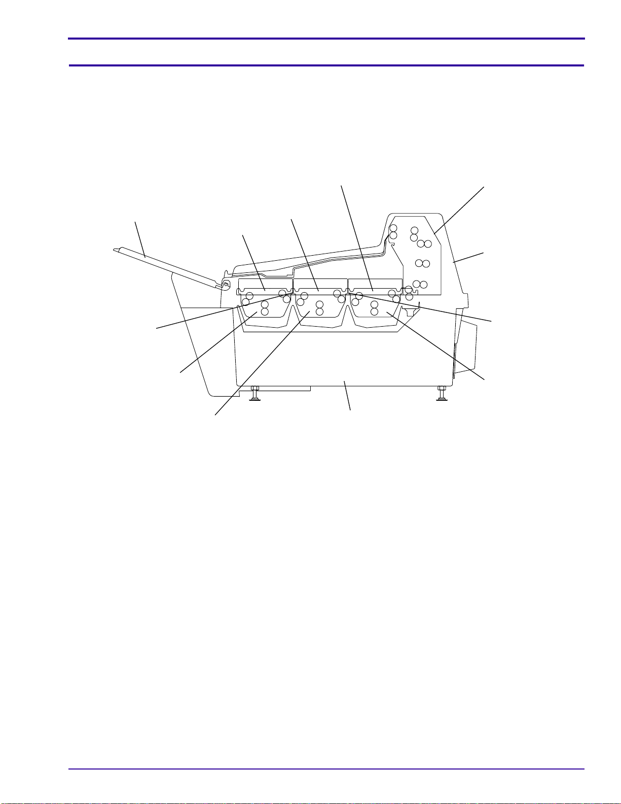
Components . . . . . . . . . . . . . . . . . . . . . . . . . . . . . . . . . . . . . . . . . . . . . . . . . . . . . . . . . . . 5
PROCESSOR Frequency . . . . . . . . . . . . . . . . . . . . . . . . . . . . . . . . . . . . . . . . . . . . . . . . . 6
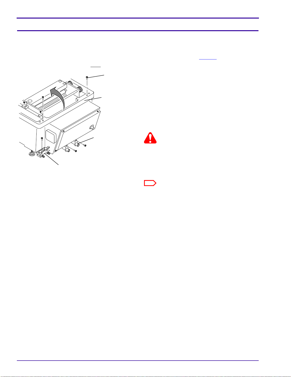
Changing the PROCESSOR Frequency . . . . . . . . . . . . . . . . . . . . . . . . . . . . . . . . . . 6
PROCESSOR Voltage . . . . . . . . . . . . . . . . . . . . . . . . . . . . . . . . . . . . . . . . . . . . . . . . . . . 8
Checking and setting the PROCESSOR voltage. . . . . . . . . . . . . . . . . . . . . . . . . . . . 8
Installing the PROCESSOR . . . . . . . . . . . . . . . . . . . . . . . . . . . . . . . . . . . . . . . . . . . . . . . 10
Connecting the Plumbing. . . . . . . . . . . . . . . . . . . . . . . . . . . . . . . . . . . . . . . . . . . . . . 10
Installing the FEED TRAY . . . . . . . . . . . . . . . . . . . . . . . . . . . . . . . . . . . . . . . . . . . . . 12
Leveling the PROCESSOR . . . . . . . . . . . . . . . . . . . . . . . . . . . . . . . . . . . . . . . . . . . . 12
Function Checkout . . . . . . . . . . . . . . . . . . . . . . . . . . . . . . . . . . . . . . . . . . . . . . . . . . . 13
Setting the Developer Temperature. . . . . . . . . . . . . . . . . . . . . . . . . . . . . . . . . . . . . . 15
Setting the Developer and Fixer Replenishment Rates . . . . . . . . . . . . . . . . . . . . . . . 16
Setting the Processor to the “Regular” Replenishment Mode . . . . . . . . . . . . . . . . . . 17
Setting the Processor to the “Flooded” Replenishment Mode . . . . . . . . . . . . . . . . . . 17
Setting the DRYER Temperature. . . . . . . . . . . . . . . . . . . . . . . . . . . . . . . . . . . . . . . . 18
Final Pre-Operation Checks. . . . . . . . . . . . . . . . . . . . . . . . . . . . . . . . . . . . . . . . . . . . 18

General Information
9B8948 – 15JUN98 3
Section 1: General Information
Electrostatic Discharge
Overview ESD, electrostatic discharge, can damage sensitive electronic parts and assemblies. You cannot
detect a static charge of 3,500 Volts, but a static charge of only 30 Volts can damage some electronic
components.
Preventive Procedures
• Check for ESD warnings on all static sensitive components, such as CIRCUIT BOARDS, before
doing any procedures.
• Use a GROUNDING STRAP when handling static sensitive components.
Special Tools
• LEVEL
• MAGNETS

INSTALLATION INSTRUCTIONS
4 15JUN98 – 9B8948
Section 2: Unpacking the PROCESSOR
The Processor and accessories are packed in 2 cartons. Before unpacking, check the cartons for damage. If the
cartons are damaged contact the Dealer before unpacking the cartons.
Important
When removing packing material, be careful not to cut through the wrapping material which can cause damage to
components.
[1] Open the cartons and remove the packing material.
[2] Remove the contents of the carton.
[3] Use the packing list to check that all contents are included.
Note
There might be parts packed with the PROCESSOR which are not used in the installation.

Components
9B8948 – 15JUN98 5
Section 3: Components
Components of the processing systems are identified by different color LABELS:
• Developer components have red LABELS.
• Fixer components have blue LABELS.
• Wash components either have white LABELS, or they are unlabeled.
H164_0043HC
WASH RACK
CROSSOVER
FIX/WASH
FIXER RACK
RACK
DEVELOPER
FIXER CROSSOVER
DEVELOPER/
FEED TRAY
WASH SECTION
FIXER SECTION
DEVELOPER
SECTION
DRYER
PROCESSOR
COVER
PROCESSOR
H164_0043HCB

INSTALLATION INSTRUCTIONS
6 15JUN98 – 9B8948
Section 4: PROCESSOR Frequency
Changing the PROCESSOR Frequency
Check the frequency of the main power at the site. The PROCESSOR must be set for the same frequency as the
main power.
The PROCESSOR has two HELICAL GEARS:
• The 50 Hz HELICAL GEAR is white.
• The 60 Hz HELICAL GEAR is black.
[1] If the correct HELICAL GEAR is installed on the
PROCESSOR, advance to Step 10. If the correct
HELICAL GEAR is not installed on the
PROCESSOR, use this procedure to replace the
Gear.
[2] Remove the E-Ring from the Shaft. Keep the E-
RING.
[3] Pull the HELICAL Gear up to remove it from the
Shaft.
[4] Loosen, but do not remove, the 4 Motor MOUNT
Screws.
[5] Place the new HELICAL Gear on the Shaft.
[6] Engage the groove on the GEAR with the Pin on
the Shaft.
[7] Install the E-Ring.
[8] Move the HELICAL GEAR toward the DRIVE
GEAR so the GEARS engage with minimum play.
[9] Tighten the Motor MOUNT Screws.
50 Hz
60 Hz
H164_0008AC
GEAR
DRIVE
PIN
SHAFT
HELICAL GEAR
E-RING
SCREWS (4)
MOTOR MOUNT
H164_0008ACA

PROCESSOR Frequency
9B8948 – 15JUN98 7
Possible damage from electrostatic discharge.
ESD
[10] Remove the 4 SCREWS and the CONTROL BOX COVER for access to the SWITCHES inside.
[11] Place the TAB on the CONTROL BOX COVER in the SLOT on the PROCESSOR.
[12] Set the PROCESSOR to the correct frequency:
(a) Move SW02-1 to the “ON” Position for 50 Hz operation or “OFF” for 60 Hz.
(b) Check that the SWITCHES are in the “OFF” position:
• SW02-1
• SW02-3
• SW02-4
Note
The CONTROL BOARD can be moved to the other end of the CONTROL BOX. If the holes at one end are not used,
cover them with TAPE.
H164_0003HC
SLOT
H164_0003HCB
CONTROL
BOARD
TAB
CONTROL
BOX COVER SWITCHES

INSTALLATION INSTRUCTIONS
8 15JUN98 – 9B8948
Section 5: PROCESSOR Voltage
Checking and setting the PROCESSOR voltage
If the PROCESSOR is a 1000A or 1000J, advance to Installing the PROCESSOR on Page 10.
If the PROCESSOR is a 1000, you must check the internal voltage setup and change the voltage setup if necessary:
[1] Open the PROCESSOR:
(a) Remove the 2 SCREWS on top of the feed
end of the PROCESSOR.
(b) RemovetheSCREWfromtheDEVELOPER
and FIXER DRAIN VALVE BRACKET.
(c) Remove the SCREWS from the WASH
WATER OVERFLOW and WASH WATER
DRAIN FITTINGS under the front of the
PROCESSOR.
Warning
The top of the PROCESSOR does not automatically
remain up. You must hold the top of the PROCESSOR
up or it will fall.
(d) Slowly open the top of the PROCESSOR.
There is a HINGE at the dryer end.
Note
The HOSES might prevent you from opening the
PROCESSOR. Feed the HOSES into the
PROCESSOR as you open it.
H164_0076AC
DRAIN FITTINGS
OVERFLOW and
WASH WATER
DRAIN VALVE BRACKET
DEVELOPER/FIXER
PROCESSOR
2 SCREWS
H164_0076ACA

PROCESSOR Voltage
9B8948 – 15JUN98 9
[2] Remove the ELECTRICAL COVER.
[3] Determine the voltage of the power source at the site. It must be 220, 230 or 240 V AC.
[4] Locate TERMINAL BLOCK TB51 inside the PROCESSOR.
[5] Use the following table to select the correct voltage setup for the PROCESSOR.
[6] Move WIRE 6 to the correct location.
[7] Install the ELECTRICAL COVER.
[8] Close the PROCESSOR and install the following:
• DEVELOPER and FIXER DRAIN VALVES and BRACKET
• WASH WATER OVERFLOW and WASH DRAIN FITTINGS
• 2 SCREWS on the top of the PROCESSOR
Note
Be careful not to bend the HOSES when you close the PROCESSOR.
[9] Label the DATA PLATE on the back of the PROCESSOR with the internal voltage setup.
[10] Advance to Installing the PROCESSOR on Page 10.
Voltage at site TERMINAL on TB51
220 V AC 5
230 V AC 6
240 V AC 7
H164_0077HC
1234567
5, 6, and 7
TERMINALS
SCREW
WIRE 6
ELECTRICAL COVER
H164_0077HCA

INSTALLATION INSTRUCTIONS
10 15JUN98 – 9B8948
Section 6: Installing the PROCESSOR
Connecting the Plumbing
Warning
• Drains must be made of chemically resistant, non-corrosive material. Use PVC or equivalent.
• The Drain must have a minimum diameter of 7.6 cm (3 in.) and be free of obstruction.
• Drain service must comply with local codes.
Components of the processing systems are identified by different color LABELS:
• Developer HOSES have red LABELS.
• Fixer HOSES have blue LABELS.
• Wash HOSES either have white LABELS, or they are unlabeled.
[1] Use the figure to connect the HOSES.
[2] Connect the PROCESSOR to the water supply.
Note
A 50 micron FILTER for the water supply is recommended.

Installing the PROCESSOR
9B8948 – 15JUN98 11
H164_0078DC
WASH WATERDEVELOPER
* CONTAINERS NOT SUPPLIED WITH PROCESSOR
or DRAIN*
CONTAINER
DRAIN
CONTAINER*
REPLENISHMENT
FIXER
CONTAINER*
REPLENISHMENT
DEVELOPER
or DRAIN*
CONTAINER
DRAIN
or DRAIN*
CONTAINER
FIXER DRAIN
H164_0078DCA
WATER
SUPPLY
FITTING
FIXER
OVERFLOW
HOSE
DEVELOPER
OVERFLOW
HOSE HOSE
CLAMP
FIXER
DRAIN HOSE
DEVELOPER
DRAIN HOSE
HOSE
CLAMP
HOSE CLAMP
WATER
OVERFLOW HOSE
WATER DRAIN
HOSE/ORIFICE
FIXER
TUBE/HOSE/FILTER
ASSEMBLY
TUBE/HOSE/FILTER
DEVELOPER
ASSEMBLY

INSTALLATION INSTRUCTIONS
12 15JUN98 – 9B8948
Installing the FEED TRAY
Possible damage from electrostatic discharge.
ESD
[1] Remove the 4 NUTS and WASHERS from the
CONTROL BOX COVER.
[2] Insert the FILM SENSOR CABLE through the
hole in the top of the CONTROL BOX.
[3] Press the GROMMET on the CABLE into the hole
on the CONTROL BOX.
[4] Install the FEED TRAY on the CONTROL BOX
using the 4 NUTS and WASHERS. Do not tighten
the NUTS.
[5] Connect the FILM SENSOR CABLE to the CN07
CONNECTOR on the BOARD in the CONTROL
BOX.
[6] Pull the FEED TRAY towards the front of the
PROCESSOR.
[7] Tighten the NUTS.
Leveling the PROCESSOR
Important
The PROCESSOR must be leveled for correct operation.
[1] Place the LEVEL on the non-drive side of the PROCESSOR and adjust the LEVELING SCREWS if necessary.
[2] Place the LEVEL on the back of the PROCESSOR and adjust the LEVELING SCREWS if necessary.
Note
Do not loosen the LEVELING SCREWS excessively or they might fall out.
H164_0045GC
BOX
CONTROL
GROMMET
CN07
FEED TRAY
4 NUTS
4 WASHERS
CABLE
FILM SENSOR
H164_0045GCA
H164_0012BC
LEVELING SCREW
NUT
LOCKING
H164_0012BCA

Installing the PROCESSOR
9B8948 – 15JUN98 13
[3] Remove the tape from the SCREENS in the bottom of the DEVELOPER and FIXER TANKS.
[4] Check the RACKS for squareness. Use the Adjustments and Replacements Section of the SERVICE MANUAL
if necessary.
[5] Install all RackS and CROSSOVERS.
Note
Check that the clear EVAPORATION COVER is correctly installed and snapped into position on the DEVELOPER
RACK.
[6] Check that the MAIN GEAR on each RACK correctly engages the WORM GEARS.
[7] Close all of the DRAIN VALVES.
[8] Fill the DEVELOPER and FIXER TANKS on the
PROCESSOR with water until the water begins to
enter the OVERFLOW HOSES.
[9] Observe the depth of the water around the
RACKS. The ROLLERS should be uniformly
immersed in the solutions.
[10] If necessary, level the PROCESSOR using the
LEVELING SCREWS.
[11] Tighten the LOCKING NUT on each LEVELING
SCREW.
[12] Fill the DEVELOPER and FIXER
REPLENISHMENT TANKS with developer and
fixer solution. See the OPERATOR MANUAL.
Function Checkout
[1] Connect the PROCESSOR to the main power.
[2] Move the POWER SWITCH to the “ON” or “I”
position.
Warning
Be careful of the DRIVE SHAFT, GEARS and other
moving parts.
[3] Place MAGNETS on the PROCESSOR over the
COVER INTERLOCK SWITCHES so the DRIVE
MOTOR will operate without the PROCESSOR
COVER. Observe the inside edge of the
PROCESSOR COVER and determine the correct
position for the MAGNETS on the PROCESSOR.
[4] Allow the PROCESSOR to operate for 10 minutes. Check that the following systems operate correctly:
• The DRIVE SHAFT should operate continually for 5 minutes, then operate intermittently.
• The DRYER BLOWER should operate for 5 minutes.
• The WATER SOLENOID should operate and fill the WASH TANK.
• The “Low t“ INDICATOR should illuminate. This indicates the developer temperature is below the set•point.
• The RECIRCULATION PUMPS should operate for 5 minutes.
H164_0013AC
OPEN
CLOSED
H164_0067AC
H164_0067ACA
MAGNETS

INSTALLATION INSTRUCTIONS
14 15JUN98 – 9B8948
[5] Check the flow of developer and fixer solution in the DEVELOPER and FIXER TANKS.
[6] If there is solution flow in both TANKS, advance to Step 8.
[7] If there is no solution flow in a TANK, there might be air in the RECIRCULATION PUMP. Use the following steps
to correct the problem:
(a) WiththePROCESSORenergized,openthe DRAINVALVEfortheTANKtorelease someof thewaterfrom
the TANK. Do not drain the TANK.
(b) Observe the TANK for flow.
(c) If there is no flow in the TANK, repeat the steps above. Add more water to the TANK, if necessary, before
opening the DRAIN VALVE again. Be careful not to drain the TANK when releasing water.
(d) When the problem is corrected, fill the TANK with solution and advance to the next step.
[8] If the PROCESSOR operates correctly, move the POWER SWITCH to the “OFF” or ”O” position.
[9] Remove the MAGNETS from the top of the PROCESSOR.
[10] Drain the DEVELOPER and FIXER TANKS by opening the DRAIN VALVES. The WASH TANK will drain
automatically.
[11] Close the DEVELOPER and FIXER DRAIN VALVES.

Installing the PROCESSOR
9B8948 – 15JUN98 15
Setting the Developer Temperature
Possible damage from electrostatic discharge.
ESD
[1] To set the developer temperature between
32.0°C and 35.0°C (89.6°F and 95.0°F):
(a) Move SW05-1 to the “OFF” position.
(b) Adjust SW03 using the following table:
Developer Temperature, 32°C - 35°C (89.6°F -
95.0°F)
[2] To set the developer temperature between
35.0°C and 38.0°C (95.0°F and 100.4°F):
(a) Move SW05-1 to the “ON” position.
(b) Adjust SW03 using the following table:
Developer Temperature, 35°C - 38°C (95.0°F -
100.4°F)
7
8
B
D
C
1
0
2
F
E
5
4
3
6
A
9
F
0
1
2
3
4
5
6
7
8
9
A
B
C
D
E
ON
4
3
2
1
DEV TEMP
ADD
SET
SW05
SW04
SW03
H164_0038AC
SW05-1 OFF, Adjust SW03:
Set•
point Temperature Set•
point Temperature
0 32.0°C (89.6°F) 8 33.6°C (92.5°F)
1 32.2°C (90.0°F) 9 33.8°C (92.8°F)
2 32.4°C (90.3°F) A 34.0°C (93.2°F)
3 32.6°C (90.7°F) B 34.2°C (93.6°F)
4 32.8°C (91.0°F) C 34.4°C (93.9°F)
5 33.0°C (91.4°F) D 34.6°C (94.3°F)
6 33.2°C (91.8°F) E 34.8°C (94.6°F)
7 33.4°C (92.1°F) F 35.0°C (95.0°F)
SW05-1 ON, Adjust SW03:
Set•
point Temperature Set•
point Temperature
0 35.0°C (95.0°F) 8 36.6°C (97.9°F)
1 35.2°C (95.4°F) 9 36.8°C (98.2°F)
2 35.4°C (95.7°F) A 37.0°C (98.6°F)
3 35.6°C (96.1°F) B 37.2°C (99.0°F)
4 35.8°C (96.4°F) C 37.4°C (99.3°F)
5 36.0°C (96.8°F) D 37.6°C (99.7°F)
6 36.2°C (97.2°F) E 37.8°C (100.0°F)
7 36.4°C (97.5°F) F 38.0°C (100.4°F)

INSTALLATION INSTRUCTIONS
16 15JUN98 – 9B8948
Setting the Developer and Fixer Replenishment Rates
Possible damage from electrostatic discharge.
ESD
[1] Use the following table to select the correct
replenishment rate:
(a) Adjust SW06 to set the developer
replenishment rate.
(b) Adjust SW07 to set the fixer replenishment
rate.
Note
SW08 is not used.
H164_0039AC
SW05 SW06 SW07
DEV FIX
RPL
1234
ON
1
0
2
5
4
3
7
8
6
9
3
2
9
1
0
8
4
5
6
7
SWITCH Set•point Volume, cc*
60 Hz, SW02-1 OFF.
PUMP ON Time,
seconds
50 Hz, SW02-1 ON.
PUMP ON Time,
seconds
0 50 7.0 8.4
1 60 8.4 10.0
2 70 9.8 11.6
3 80 11.2 13.4
4 90 12.6 15.0
5 100 14.0 16.6
6 110 15.2 18.4
7 120 16.6 20.0
8 130 18.0 21.6
9 140 19.4 23.4
* Volume for film size 35 x 43 cm (11 x 14 in.)

Installing the PROCESSOR
9B8948 – 15JUN98 17
Setting the Processor to the “Regular” Replenishment Mode
Possible damage from electrostatic discharge.
ESD
[1] Move SW05-3 to the “OFF” position.
[2] Install the CONTROL BOX COVER.
Setting the Processor to the “Flooded” Replenishment Mode
Possible damage from electrostatic discharge.
ESD
[1] Move SWITCH SW05-3 to the “ON” position.
[2] Select the replenishment for the “Flooded” Mode:
(a) Move SW05-4 to the “ON” position for
“Flooded” replenishment at 50% of the
operating mode rate.
(b) Move SW05-4 to the “OFF” position for
“Flooded” replenishment at 25% of the
operating mode rate.
Note
When replenishment for the “Flooded” Mode is
selected, the REPLENISHMENT PUMPS will operate
every 20 minutes.
[3] Install the CONTROL BOX COVER.
H164_0039AC
SW05 SW06 SW07
DEV FIX
RPL
1234
ON
1
0
2
5
4
3
7
8
6
9
3
2
9
1
0
8
4
5
6
7
H164_0039AC
SW05 SW06 SW07
DEV FIX
RPL
1234
ON
1
0
2
5
4
3
7
8
6
9
3
2
9
1
0
8
4
5
6
7

INSTALLATION INSTRUCTIONS
18 15JUN98 – 9B8948
Setting the DRYER Temperature
[1] Use the following table to select and set the DRYER temperature. Count the increments between the “LOW”
and “HIGH” positions.
DRYER Temperature
Final Pre-Operation Checks
[1] Use the OPERATOR MANUAL to complete the setup of the PROCESSOR:
(a) Mix the developer and fixer solutions.
(b) Do the Procedure “Filling the Tanks in the PROCESSOR”.
[2] Process test films to check the operation of the PROCESSOR.
Position Temperature Positio
n Temperature
LOW 35°C (95°F) 8 51°C (124°F)
137°C (99°F) 9 53°C (127°F)
239°C (102°F) 10 55°C (131°F)
341°C (106°F) 11 57°C (135°F)
443°C (109°F) 12 59°C (138°F)
545°C (113°F) 13 61°C (142°F)
647°C (117°F) 14 63°C (145°F)
749°C (120°F) HIGH 65°C (149°F)
H164_0037AC
High
Low
Dryer Temperature

Installing the PROCESSOR
9B8948 – 15JUN98 19
Publication History
Print Date Pub. No. ECO No. Affected Pages File Name Notes
July 1997 9B8948 2504-470 All Pages ii3482_1_22jul97.doc First printing.
June 1998 9B8948 All Pages ii3482_1_15jun98.doc Second printing.

Printed in U.S.A. • ii3482_1.fm
EASTMAN KODAK COMPANY
Rochester, NY 14650 HEALTH IMAGING
Kodak
and
X-Omat
are trademarks.
This manual suits for next models
2
Table of contents
Other EASTMAN Medical Equipment manuals
Popular Medical Equipment manuals by other brands

Osprey Medical
Osprey Medical R-RRL Instructions for use

Otto Bock
Otto Bock 2R8 Series Instructions for use

Cardinal Health
Cardinal Health NPWT PRO Patient Quick Reference Guide

Atmos
Atmos Chair M 2 operating instructions

Atmos
Atmos S 201 Thorax Short operating instructions

HCO
HCO ADAMM-RSM quick start guide

Drive DeVilbiss Sidhil
Drive DeVilbiss Sidhil Athena Quick Glance User Guide

Otto Bock
Otto Bock 50K90 Agilium Softfit Instructions for use

Ergotron
Ergotron StyleView SV43 Tech sheet

SoftGuards
SoftGuards MLE09065 quick start guide

steute
steute MKF 3 2S SW2.4LE-MED GP311 manual

NeurOptics
NeurOptics PLR-4000 quick start guide