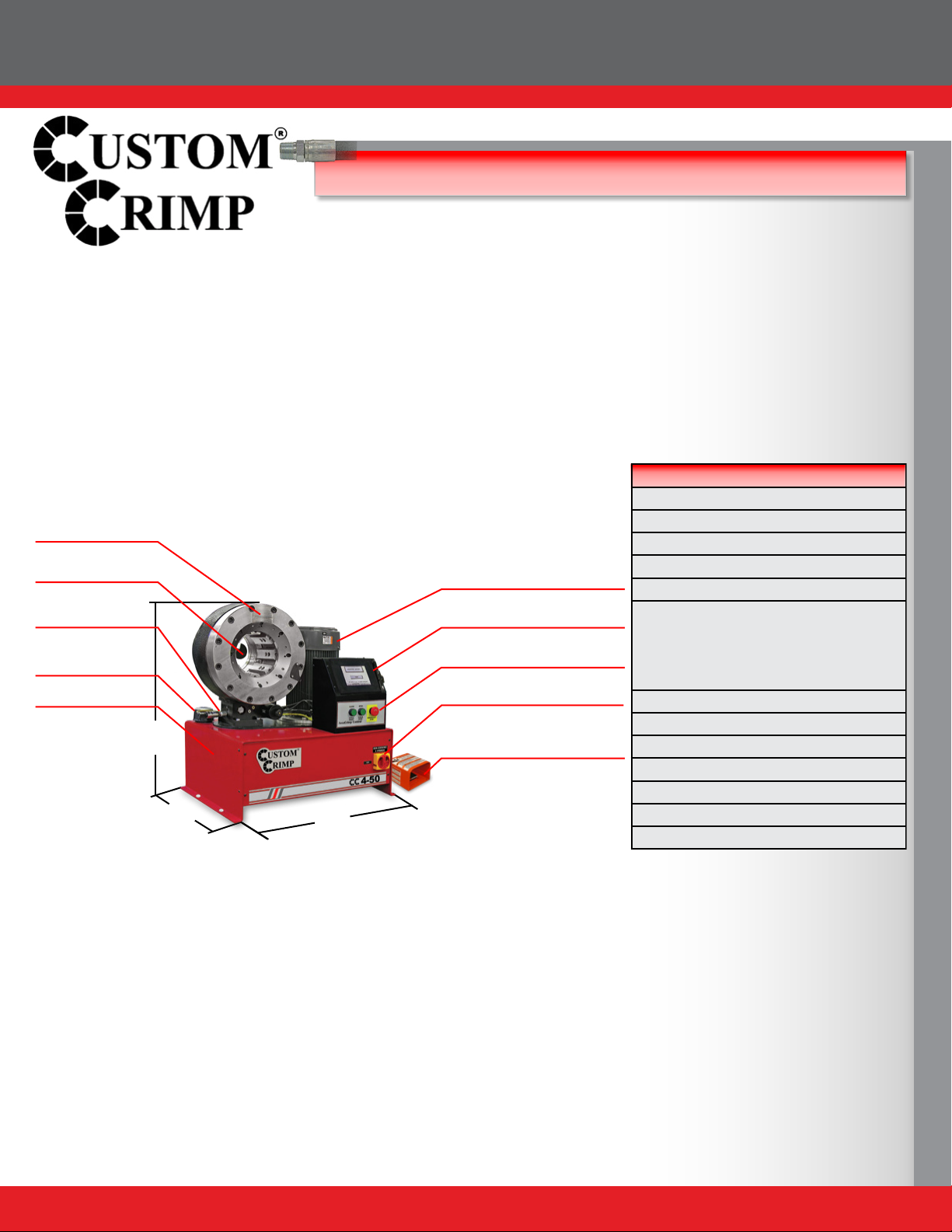
CC4-50 General Production Hose Crimper
5
INITIAL SET UP & MAINTENANCE
Do not lift the machine by the crimper head.
Lift with a fork lift under the tank.
Mount the crimper on a sturdy surface.
Check electrical circuit to be certain that it matches the crimper
requirements shown on the tag attached to the crimper cord.
Electrical Requirements:
220 Volt 3 Phase Current (Standard)
440 Volt 3 Phase Current (Optional)
DO NOT RUN CRIMPER ON AN EXTENSION CORD.
Check to be certain that the motor rotates in the direction of the arrow
shown on the motor housing. If motor rotation is opposite of the direction
of the arrow, reverse any two hot wires in the electrical plug.
(NOTE: THIS IS APPLICABLE TO 3 PHASE CIRCUITS ONLY).
Damage to the pump can result if the motor does not rotate in the
correct direction.
Check the oil level in the sight glass on the rear of the crimper. 8 U.S,
gallons of ISO 46 hydraulic oil are required to completely rell the tank.
Oil can be drained from either of the two ports at the bottom of the tank.
An additional oil cooler, while not normally required, can be plumbed
into the two ports at the rear of the crimper.
Front Flange Bolts: Periodically, every 6-12 months depending upon
usage, the front ange bolt torque should be checked. The correct torque
is 332NM (245 Ft-Lbs).
Lubricate the crimping head after each 100 crimping cycles or at the
start of each shift if the crimper is used in a production setting.
• Bring the master dies to the fully closed position and lubricate the die
ngers through the 8 lubrication ttings in the front ange face.
• Bring the dies to the fully open position and lubricate all 8 ttings again.
Use CRIMPX Die Lubricant Grease or a high quality moly-disulde
grease. Failure to do so may result in damage to the wearing surfaces.