CustomCrimp D105-T420 SERIES User manual

Innovating SMART Hose Assembly Solutions Since 1979
1
D105-T420 SERIES HYDRAULIC CRIMPERS
OPERATORS MANUAL

Innovating SMART Hose Assembly Solutions Since 1979
2
• READ INSTRUCTIONS AND IDENTIFY ALL COMPONENT PARTS BEFORE USING CRIMPER.
• D105-T420 SERIES CRIMPERS CAN PRODUCE 35 TONS OF CRIMPING FORCE.
• KEEP BOTH HANDS AWAY FROM PINCH POINTS.
• CONSULT HOSE AND FITTING MANUFACTURER FOR CORRECT MACHINE SETTINGS
AND CRIMP MEASUREMENTS.
• ALWAYS WEAR EYE PROTECTION.
SAFETY PRECAUTIONS
! !
Rev: 05/2023

Innovating SMART Hose Assembly Solutions Since 1979
3
SAFETY PRECAUTIONS-------------------------------------------------------------------------------------------------------------2
COMPONENT PARTS & TECHNICAL DATA--------------------------------------------------------------------------------------------------4
AVAILABLE D105 / D165 D-SERIES DRAWER ASSEMBLY / STAND---------------------------------------------------------------5
FEATURES---------------------------------------------------------------------------------------------------------------6
INITIAL SET UP-----------------------------------------------------------------------------------------------------------------------7
LUBRICATION PROCEDURE--------------------------------------------------------------------------------------------8
CRIMPING WITH STANDARD T420 PRESSURE PLATE---------------------------------------------------------------------------------9
CRIMPING WITH NOTCHED T420 PRESSURE PLATE-----------------------------------------------------------------------------13
CALIBRATION CHECK PROCEDURE---------------------------------------------------------------------------------17
D105 / D165 D-SERIES DRAWER ASSEMBLY / STAND (INSTRUCTIONS)------------------------------------------------------20
INCLUDED ACCESSORIES----------------------------------------------------------------------------------------21
AVAILABLE ACCESSORIES---------------------------------------------------------------------------------------22
TROUBLESHOOTING---------------------------------------------------------------------------------------------------------23
COMPONENT PARTS BREAKDOWN--------------------------------------------------------------------------------------------24
CUSTOM CRIMP® “NO-NONSENSE” WARRANTY STATEMENT---------------------------------------------------------------27
CUSTOM CRIMP®CONTACT INFORMATION--------------------------------------------------------------------------------------28
TABLE OF CONTENT

Innovating SMART Hose Assembly Solutions Since 1979
4
D160/D165 Pusher
Standard D105
T420 Pressure Plate
T420 Rubber Caged
Die Series
*Crimper capacity is estimated based on typical
1-piece tting. Actual results may vary depending
on the tting and hose manufacturer.
13"
22"
22-½" 1HP/110V/Single Phase
pump for fast crimps
Small Footprint for
minimum use of space
Power Switch
Electrical Enclosure
Adjustable Retraction Stop
Powerful 35 Ton
Hydraulic Cylinder
Removable Pusher
Adjustment Screw
T420 RubberCaged
Die Series
Reservoir
Pneumatic Switch
T420 Pressure Plate
Micrometer Style
Adjustment
Voltage Tag
Electronic Shut O
D105-T420 Technical Specications
Crimping force: 35 Ton
Hydraulic hose capacity: 2 Wire = 1"
4 Spiral = 3/4"
Crimper size: L: 22" x W: 13" x H: 22-½"
Crimper weight: 124 lbs
Power: 1HP/110V/1Phase (Standard)
2HP/220V/1Phase (Optional)
Die series: D160-T420 Rubber Caged
Micrometer style adjustment: T420
Reservoir capacity: 1 US Gallon
Oil type: ISO 46 Hydraulic Oil
COMPONENT PARTS & TECHNICAL DATA

Innovating SMART Hose Assembly Solutions Since 1979
5
D-Series Drawer Assembly / Stand
The crimper bolts directly on
top of the mounting holes of the
D-Series Drawer.
D-Series Drawer Assembly / Stand is available for
D105-T420 / D165-T420 Series Crimpers.
D105-T420 Series Crimper
Die storage drawer to keep
frequently used die sets and
your crimping accessories
readily available.
Base mounting holes allow
the drawer to be bench or
truck bed mounted if required.
D105/D165 D-SERIES DRAWER ASSEMBLY / STAND

Innovating SMART Hose Assembly Solutions Since 1979
6
Automatic stop
switch shuts the
pump o when
the crimp cycle
is complete.
Built-in adjustable retraction
stop limits ram retraction for
quick repetitive crimps.
An easily removable Coupling
Stop makes repetitive crimps
faster by not having to visually
align the tting before each
crimp.
Easy calibration adjustment to
increase or decrease crimp OD.
T420 Micrometer “Micro-Crimp
Adjuster” is fully adjustable to
make precise and repeatable
crimps.
Open design, two piece rubber
caged die set for heavy duty
environments and removable
pusher allows the operator to
accurately position the tting
prior to crimping.
FEATURES

Innovating SMART Hose Assembly Solutions Since 1979
7
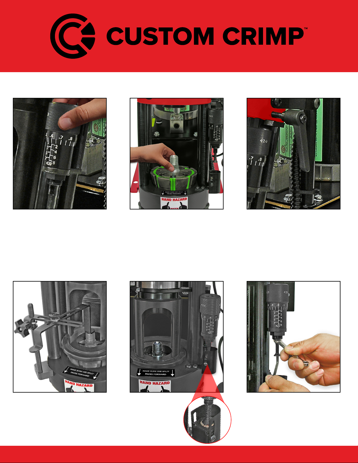
FOLLOW THESE STEPS BEFORE YOU USE THE CRIMPER
FOR THE FIRST TIME.
• Mount the crimper on a sturdy workbench in a well-lit area. Work-
bench should be able to support the crimper and components weight.
Note: The D105-T420 series crimper can be mounted on the D-Series
Drawer/Stand and bolted onto the workbench. (See detailed instruc-
tions included with D-Series drawer/stand).
• The crimper should be mounted close enough to the edge of the
work surface so that hose will not contact the bench or work surface
while crimping. There must be enough clearance for the hose to align
perpendicular with the cone base, or the dies will not seat properly
and the crimps will not be accurate.
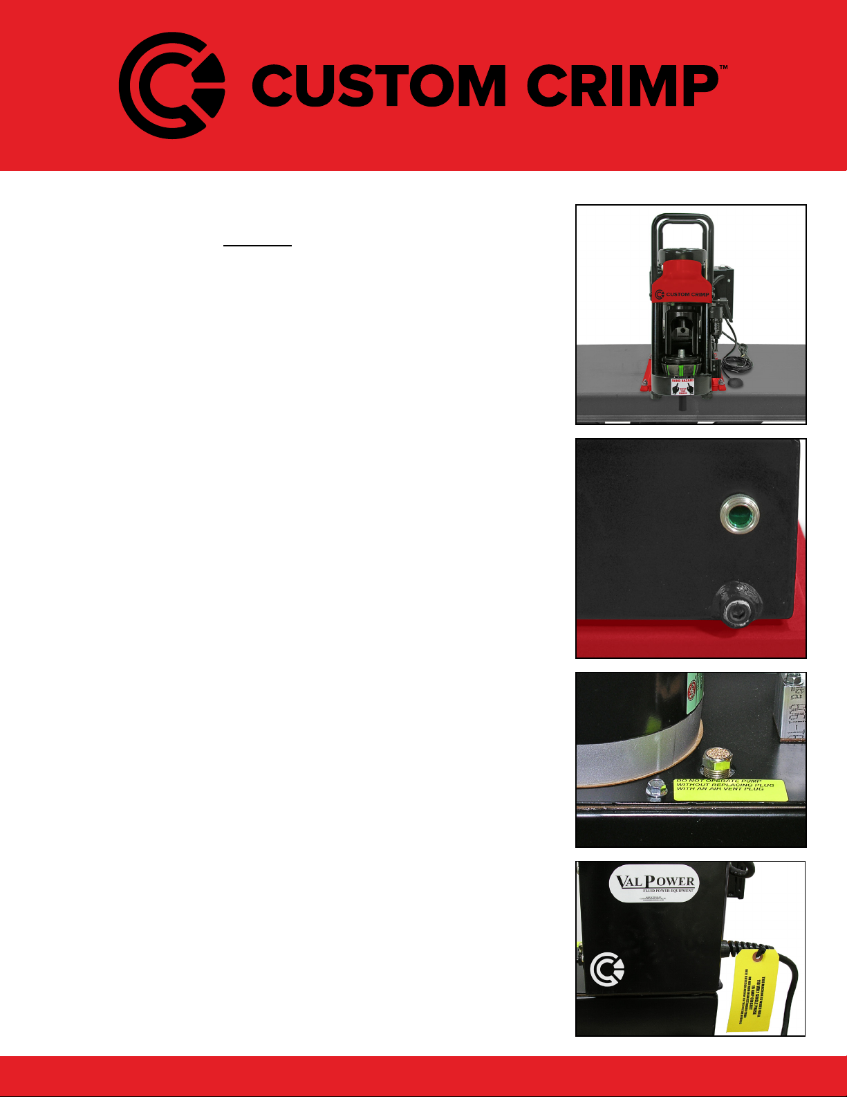
• Always check oil level in the D105-T420 pump, should be 1-1/2
to 2 inches below the vent plug when the cylinder is in the retracted
position and should be visible in the sight glass window of the pump
reservoir.
• If oil needs to be added use ISO 46 weight hydraulic oil.
• Oil can be drained from the rear oil port of the reservoir.
• Check to be certain that the shipping plug in the pump reservoir
has been replaced with the vent plug shipped with the D105-T420
crimper.
• Check electrical circuit to be certain that it matches the crimper
requirements shown on the voltage tag attached to the crimper cord.
• Plug the D105-T420 crimper directly into a 110 volt, 15 amp wall
outlet.
Note: The optional 220 volts / 2HP unit must be connected to a 220
volts 20 amp wall outlet.
INITIAL SET UP

Innovating SMART Hose Assembly Solutions Since 1979
8
Photo # 1
Photo # 2
Photo # 3
Grease Point # 1
Apply a thin layer of CrimpX oil (supplied with the
crimper), or a molybdenum disulde high pressure
grease on the surface of the cone base.
(as shown in photo # 1).
Grease Point # 2
Before sliding the standard pressure plate (or the notched
pressure plate) over the correct dies, apply a thin layer of
CrimpX oil (supplied with the crimper), or a molybdenum
disulde high pressure grease, on the entire area that the
dies come in contact with (as shown in photo # 2).
If Dies are sticking in the cone base: Continue to lubricate
/ grease as explained above, in addition to lubricating each
die nger individually (as shown in photo # 3).
Note: The die ngers must be lubricated at both positions
that come in contact with the pressure plate and the
cone base.
Note: Lubrication is not required before each crimp.
Typical lubrication is after 100 crimps.
Notched Pressure Plate:
For use with 90 degree tting only.
LUBRICATION PROCEDURE

Innovating SMART Hose Assembly Solutions Since 1979
9
Note: Follow the lubrication procedure prior to crimping procedure.
CAUTION: Failure to lubricate the die set and T420 pressure plate
could result in the die seizing in the cone base.
Step 1: Make certain that the Cone Base is clean and lubricated prior
to inserting the die set.
Step 2: Select the Correct Die Set for the combination of hose and
tting being crimped.
Note: Consult your hose and tting manufacturer for the correct die size
for the combination of hose and tting being crimped.
Note: The number etched on the OD of the die ring represents the fully
closed diameter of the die set in millimeters. In addition, rubber caged
die sets are color-coded for easier identication.
Step 3: Lubricate the contact surfaces, both the top and the outside
edges of the die ngers, with CrimpX oil (supplied with the crimper), or
a molybdenum disulde high pressure grease.
Failure to lubricate the contact surfaces with the correct lubricant
will cause the dies to seize in the cone base, causing damage
to the die set as well as possibly damaging the crimper.
CRIMPING WITH STANDARD T420 PRESSURE PLATE

Innovating SMART Hose Assembly Solutions Since 1979
10
Step 4: Place the Lubricated Die Set squarely in the cone base.
Note: Make sure the split of the die cages is facing the operator.
(as shown).
Step 6: Place the Lubricated Standard Pressure Plate over the die set.
Step 5: Align the tting in the die set according to the hose and tting
manufacturer’s recommendation.
Note: Compress the die set by hand to hold the hose and tting in place.
CRIMPING WITH STANDARD T420 PRESSURE PLATE

Innovating SMART Hose Assembly Solutions Since 1979
11
Note: Make sure the pusher is positioned correctly as shown.
Step 7: Slide the Pusher onto the pusher retaining ring on the hydraulic
cylinder.
Note: Make sure slot in pusher goes over lip on pusher retaining ring.
CAUTION: Damage to pusher and retaining ring can occur if misaligned.
Rear View
SlotSlot
Front View
Lip Lip
Pusher
Retaining Ring
CRIMPING WITH STANDARD T420 PRESSURE PLATE

Innovating SMART Hose Assembly Solutions Since 1979
12
Step 8: Set the Micro-Crimp Adjuster to the setting recommended by
the hose and tting manufacturer for the combination of hose and tting
being crimped.
NOTE: The T420 Micro-Crimp Adjuster is a direct reading
micrometer. Add the setting on the micrometer to the closed
diameter of the die set to obtain the nished crimp diameter.
For example: With a 23mm die set and the Micro-Crimp Adjuster set at
3.0, the nished crimp diameter would be 26.0 mm (23mm + 3.0mm).
Note: Each die set has a limited range of diameters for which a satisfactory
crimp can be obtained. Always consult your hose and tting manufacturer
for the correct die set for the hose and tting being crimped.
Step 9: Recheck the tting for the correct alignment in the die set and
depress the start/stop switch.
Depress and hold the Start/Stop switch, until the micrometer touched the
electronic red button as shown, “count one mississippi” the automatic
stop switch will shut the pump o, and the ram will return to the retracted
position. Allow the pusher to return to the retracted position as well.
Step 10: Check the nal crimp diameter with calipers to conrm that
it is within manufacturer’s specications.
Note: Always consult with your hose and tting manufacturer to obtain
the must current crimp specications.
CRIMPING WITH STANDARD T420 PRESSURE PLATE

Innovating SMART Hose Assembly Solutions Since 1979
13
Note: Follow the lubrication procedure prior to crimping procedure.
CAUTION: Failure to lubricate the die set and pressure plate could
result in the die seizing in the cone base.
Step 1: Make certain that the Cone Base is clean and lubricated prior
to inserting the die set.
Step 2: Select the Correct Die Set for the combination of hose and
tting being crimped.
Note: Consult your hose and tting manufacturer for the correct die size
for the combination of hose and tting being crimped.
Note: The number etched on the OD of the die ring represents the fully
closed diameter of the die set in millimeters. In addition, die sets are
rubber caged color-coded for easier identication.
Step 3: Lubricate the contact surfaces, both the top and the outside
edges of the die ngers, with CrimpX oil (supplied with the crimper), or
a molybdenum disulde high pressure grease.
Failure to lubricate the contact surfaces with the correct lubricant
will cause the dies to seize in the cone base, causing damage
to the die set as well as possibly damaging the crimper.
WHEN USING THE NOTCHED T420 PRESSURE PLATE,
FOR USE WITH 90 DEGREE FITTING ONLY,
FOLLOW THESE PROCEDURES:
CRIMPING WITH NOTCHED T420 PRESSURE PLATE

Innovating SMART Hose Assembly Solutions Since 1979
14
Step 2: Place the Lubricated Die Set squarely in the cone base.
Note: Make sure the split of the die cages is facing the operator.
(as shown).
Step 6: Place the Lubricated Notched Pressure Plate over the die set.
Note: The notched pressure plate MUST be covering
all 8 die ngers as shown.
Step 5: Align the 90 degree tting in the die set according to the hose
and tting manufacturer’s recommendation.
Note: Compress the die set by hand to hold the hose and tting in place.
CRIMPING WITH NOTCHED T420 PRESSURE PLATE

Innovating SMART Hose Assembly Solutions Since 1979
15
Step 8: After placing the notched pressure plate covering all 8 die
ngers as shown, slide the Pusher onto the pusher retaining ring on
the hydraulic cylinder.
Note: Make sure the slot in the pusher goes over the lip on the pusher
retaining ring. Refer to page 11 for details if needed.
CAUTION: Damage to the pusher and retaining ring can occur if they
are misaligned.
Note: Recheck that the notched pressure plate is covering all 8 die
ngers.
Step 7: CAUTION: DO NOT MISALIGN NOTCHED
PRESSURE PLATE OR DAMAGE WILL OCCUR.
Note: You MUST follow these steps when crimping
with the notched pressure plate.
A. Die split must face operator.
B. Notched Pressure Plate MUST to cover all 8
die ngers.
Damage can occur to the die ngers if the parts
aren’t aligned properly.
Broken Die Finger
Wrong Alignment
CRIMPING WITH NOTCHED T420 PRESSURE PLATE

Innovating SMART Hose Assembly Solutions Since 1979
16
Step 11: Check the nal crimp diameter with calipers to conrm that
it is within manufacturer’s specications.
Note: Always consult with your hose and tting manufacturer to obtain
the must current crimp specications.
Step 9: Set the Micro-Crimp Adjuster to the setting recommended by
the hose and tting manufacturer for the combination of hose and tting
being crimped.
NOTE: The T420 Micro-Crimp Adjuster is a direct reading
micrometer. Add the setting on the micrometer to the closed
diameter of the die set to obtain the nished crimp diameter.
For example: With a 23mm die set and the Micro-Crimp Adjuster set at
3.0, the nished crimp diameter would be 26.0 mm (23mm + 3.0mm).
Note: Each die set has a limited range of diameters for which a satisfactory
crimp can be obtained. Always consult your hose and tting manufacturer
for the correct die set for the hose and tting being crimped.
Step 10: Recheck the tting for the correct alignment in the die set and
depress the start/stop switch.
Depress and hold the Start/Stop switch, until the micrometer touched the
electronic red button as shown, “count one mississippi” the automatic
stop switch will shut the pump o, and the ram will return to the retracted
position. Allow the pusher to return to the retracted position as well.
CRIMPING WITH NOTCHED T420 PRESSURE PLATE

Innovating SMART Hose Assembly Solutions Since 1979
17
THE CRIMPER IS CALIBRATED PRIOR TO SHIPMENT, BUT A
CALIBRATION CHECK IS RECOMMENDED PRIOR TO USING
THE CRIMPER FOR THE FIRST TIME.
Note: Follow the lubrication procedure prior to calibration check.
CAUTION: Failure to lubricate the die set and pressure plate could
result in the die seizing in the cone base.
Step 1: Make certain that the Cone Base is clean and lubricated prior to
inserting the die set.
Step 2: Place Any Lubricated Die Set squarely in the cone base.
Note: Make sure the split of the die cages is facing the operator.
(as shown).
Step 3: Place the Lubricated T420 Pressure Plate over the die set.
Note: A hose and tting are not required for a calibration check.
CALIBRATION CHECK PROCEDURE

Innovating SMART Hose Assembly Solutions Since 1979
18
Step 4: Slide the Pusher onto the pusher retaining ring on the hydraulic
cylinder.
Note: Make sure slot in pusher goes over lip on pusher retaining ring.
Refer to page 12 for details if needed.
CAUTION: Damage to pusher and retaining ring can occur if misaligned.
Step 5: Set the T420 Micro-Crimp Adjuster at “0”.
Step 6: Depress and hold the Start/Stop switch, until the Die set is
completely closed and oil pressure has built up in the hydraulic cylinder.
If the ram extends, the dies are completely closed, the pump builds
pressure (The sound of the pump will change) when the micrometer
touched the electronic red button as shown, “count one mississippi” the
automatic stop switch will shut the pump o, and the ram will return to
the retracted position the crimper is correctly calibrated.
CALIBRATION CHECK PROCEDURE

Innovating SMART Hose Assembly Solutions Since 1979
19
Step 7: If the above conditions are not met, the crimper requires
recalibration, hold the micrometer barrel with a 5/16 inch open end
wrench and rotate the stem either in or out with a 5/32 inch hex key wrench.
Note: 1/4 turn of the screw will change crimp diameter approximately
0.008”.
• Rotating the stem out of the barrel decreases the time required for
the pump to shut o.
• Recheck calibration.
CALIBRATION CHECK PROCEDURE

Innovating SMART Hose Assembly Solutions Since 1979
20
Install (2) 3/8-16 x 1" carriage bolts in front two
holes (as shown in picture # 1). Use 3/8" plastic
retaining washer to hold bolt into place.
Slide the drawer slightly out to access two rear holes
(as shown in picture # 2). Install (2) 3/8-16 x 1" carriage
bolts in rear two holes (as shown in picture # 2). Use
3/8" plastic retaining washer to hold bolt into place.
Place the D105/D165 base plate over the 4
screws as shown in picture # 3.
Place 3/8" at washer, 3/8" locking washer, and
then the 3/8"- 16 nut over the bolt as shown.
Tighten each nut with a 9/16" wrench or socket until the
nuts are tight as shown in picture # 4.
Note: Bolt the D105/D165 D-Series drawer assembly /
stand to work surface before use.
# 1
# 3 # 4
# 2
D105/D165 D-SERIES DRAWER ASSEMBLY / STAND
Other manuals for D105-T420 SERIES
1
Table of contents
Other CustomCrimp Industrial Equipment manuals
Popular Industrial Equipment manuals by other brands

TRAILPARTS
TRAILPARTS hygo3 installation guide

Napa
Napa 791-7125 Operating manual & parts list

Stahl
Stahl 8150/5-V88 Series operating instructions

Woodward
Woodward CPC-DX Installation and operation manual

SCHUNK
SCHUNK SWG Assembly and operating manual

Emerson
Emerson Yarway Installation, operation and maintenance instructions