Cutler-Hammer Freedom 2100 Series Manual

Cutler-Hammer I.B. 8926-1A
Model A
Effective 3/01
Freedom 2100 Motor Control Center
Installation and Maintenance Manual
TABLE OF CONTENTS
PART DESCRIPTION PAGE
1General Information 2
2Receiving, Handling, & Storage 4
3Installing Control Center Sections 5
4Installing Conduit & Wiring 10
5Incoming Line Connections 12
6Overcurrent Protection Devices 14
7Overload Relay Heater Selection 16
8Inspection Prior to Energizing 19
9Unit Installation & Adjustment 20
10 Maintenance 23
11 Plan Views 31
12 Related Instruction Leaflets 33
This electrical control equipment is designed to be
installed, operated, and maintained by adequately
trained workmen. These instructions do not cover all
details, variations, or combinations of the equipment, its
storage, delivery, installation, check-out, safe operation,
or maintenance. Care must be exercised to comply with
local, state, and national regulations, as well as safety
practices, for this class of equipment. The maximum
short circuit capability of the equipment should not be
exceeded by connection to a source with higher
capacity.
If maintenance or troubleshooting assistance is required,
contact your nearest Cutler-Hammer Sales Office.

2I.B. 8926-1A
Part 1
GENERAL INFORMATION
THE MOTOR CONTROL CENTER
The Cutler-Hammer Freedom 2100 Motor Control
Center may be joined to existing Five Star, Series
2100, and Advantage installations using the splice
bar kits common to both. Units designed for the
Freedom 2100 can be mounted in Five Star Series
and Series 2100 sections, but the opposite is not
recommended, because Five Star and Series 2100
units may lack terminal blocks and sufficient
interrupting capacity. The Freedom 2100 MCC
may be joined to existing Cutler-Hammer Freedom
Unitrol and F10 Unitrol MCC’s with a special splice
bar kit, but units are not interchangable.
CONTROL CENTER NOMENCLATURE
The numbers shown in parentheses in the
following text refer to the balloon legends in Figure
2.
The Cutler-Hammer Freedom 2100 Motor Control
Center consists of one or more totally enclosed,
dead front, free standing structural assemblies (17)
90 inches high which are compartmentalized to
house individual control units. (2) With control units
mounted in the front side only, the structure may
be 16 or 21 inches deep. For mounting units back-
to-back, the structure is 21 inches deep. Steel
covers (7) enclose the structure at the top, sides
and at the rear of front-mounted-only structures.
A vertical bus system (13) installed in each vertical
section is connected to the horizontal bus to feed
the individual control units. (14) The vertical bus is
isolated by a full height barrier. (6) An optional
labyrinth barrier provides both isolation and
insulation. An automatic shutter is included with the
labyrinth barrier system to cover the stab openings
for each control unit.
At the top of each section, a door provides ready
access to the top horizontal wireway (11) and
ground bus (8). The horizontal wireway is isolated
from the bus systems by steel barriers (10) which
can be removed for installation and maintenance
operations. Adequate space is provided for control
wiring and top cable entry.
At the bottom of each section, a door (18) provides
ready access to the bottom horizontal wireway,
(19) and neutral bus (if provided). The bottom of
each section is completely open to provide
unrestricted bottom entry of cable and conduit.
Channel sills may be installed across the bottom of
the control center if specified, and an optional
bottom plate may also be specified.
A vertical wireway 8 inches deep, (16) extending
the full 90 inch height of the control center is
located to the right of each unit compartment. This
wireway is covered by two hinged doors (15) and
contains cable supports to secure wire bundles
and cables. The vertical wireway joins the
horizontal wireway at the top and bottom to provide
unobstructed space for interwiring.
Each vertical section provides space to mount up
to six controller units (2) with a minimum height of
12 inches, in increments of six inches, for a total of
72 inches of usable space. Controllers through
NEMA Size 5 are drawout type (except reduced-
voltage starters). These drawout unit assemblies
are a completely self-contained package consisting
of a steel enclosure, operating handle and
electrical components. The drawout assembly
slides into this compartment on guide rails (11) to
provide easy withdrawal and reinsertion and to
ensure precise alignment of the unit stabs with the
vertical bus. Each drawout unit is held in place by a
single quarter-turn latch (4) which can only be
engaged when the unit stabs are fully mated with
the vertical bus. Each unit has a separate door, (1)
held closed by a minimum of two quarter-turn
fasteners.
The operating handle on the controller unit (3)
moves vertically. In the ON or TIPPED positions,
the handle interlocks with the unit door to prevent
its opening. In this position, authorized personnel
can open the door by turning the defeater
mechanism screw. (21) With the unit door open
Fig. 1 Nameplate

3I.B. 8926-1A
Fig. 2 Motor Control Center Nomenclature
and the operating handle in the ON position,
another interlock to the divider pan prevents
removal of the unit. This same interlock prevents
insertion of the unit unless the handle mechanism
is in the OFF position. To ensure that units are not
energized accidentally or by unauthorized
personnel, the handle mechanism can be
padlocked in the OFF.position. Space for a
minimum of three padlocks is provided on each
handle.The device panel (5) is mounted on the
drawout unit. It will accommodate up to six pilot
devices. The overload reset button (20) is mounted
on the unit door.
(1)
Unit Door
(2)
Drawout
Unit
(4)
¼ Turn Latch
(3)
Operating
Handle
(5)
Device Panel
and Devices
(7)
Top & Side
Covers
(6)
Vertical Bus Barrier
– Labyrinth
(Optional)
(8) Ground Bus
(9) Top
Horizontal
Wireway
(10) Horizontal Bus
Barriers
(12)
Horizontal
Bus
(13)
Vertical
Bus
(11)
Divider Pan/
Guide Rails
(14)
Vertical Bus
Barrier -
Standard
(15)
Vertical
Wireway
Door
(16)
Vertical
Wireway
(17)
Structural
Members
(18)
Bottom
Horizontal
Wireway Door
(19)
Bottom
Horizontal
Wireway
(20)
Overload
Reset Button
(21)
Defeater
Mechanism Screw

4I.B. 8926-1A
RATINGS
Each Freedom 2100 Motor Control Center has a
rating nameplate attached to the door of the top
horizontal wireway of the primary section. See
Figures 1 and 2. This nameplate shows the general
order number under which the motor control center
was built and its continuous electrical ratings, in
terms of incoming line voltage, phases, and
frequency, and ampere ratings of the horizontal bus
and the vertical bus for each section. In addition, this
nameplate shows the passive short-circuit
(withstand) rating of the horizontal and vertical bus
system.
The active short-circuit (interrupting) ratings of the
main and unit short-circuit protective devices are
shown on labels attached to the inside of each unit.
Before installing a motor control center, calculate
and record the fault current available at the incoming
line terminals. Verify that the short-circuit withstand
and short-circuit interrupting ratings of the units in
the motor control center are appropriate for the fault
current available.
QUALIFIED PERSONNEL
Individuals who install, operate or maintain motor
control centers must be trained and authorized to
operate the equipment associated with the
installation and maintenance of a motor control
center, as well as the operation of the equipment
that receives its power from controller units in the
motor control center.
Such individuals must be trained in the proper
procedures with respect to disconnecting and
locking OFF power to the motor control center,
wearing protective clothing and equipment, and
following established safety procedures as outlined
in the National Electrical Safety Code(ANSI C2)
and Electrical Equipment Maintenance(NFPA
70B).
Part 2
RECEIVING, HANDLING, AND STORAGE
RECEIVING
Before and after unloading the motor control center,
inspect each section and unit exterior for evidence of
damage that may have been incurred during
shipment. If there is any indication that the control
center has been mishandled or shipped on its back
or side, remove the drawout units and make a
complete inspection of the internal structure, bus
bars, insulators and unit components for possible
hidden damage. Report any damage found to the
carrier at once.
HANDLING
The following guidelines are provided to help avoid
personal injury and equipment damage during
handling, and to facilitate moving the motor control
center at the job site.
GENERAL HINTS
1. Handle the motor control center with care, to
avoid damage to components and to the
enclosure or its paint finish.
2. Keep the motor control center in an upright
position.
3. Insure that the moving means has the capacity
to handle the weight of the motor control center.
4. The control center should remain secured to the
shipping skid until the motor control center is in
its final location.
5. Exercise care during any movement and
placement operations to prevent falling or
unintentional rolling or tipping.
6. Lifting angles for handling by overhead crane
are bolted to the top of each shipping section.
Handling by overhead crane is preferable but
when crane facilities are not available, the motor
control center can be positioned with a fork-lift
truck or by using rollers under the shipping skid.
OVERHEAD CRANE
1. See Figure 3 for recommended lifting
configuration.
2. Select or adjust the rigging lengths to
compensate for any unequal weight distribution,
and to maintain the motor control center in an
upright position.
3. To reduce tension on the rigging and the
compressive load on the lifting angles, do not
allow the angle between the lifting cables and
vertical to exceed 45 degrees.
4. Use slings with safety hooks or shackles. Do
not pass ropes or cables through lifting
angle holes.

5I.B. 8926-1A
Figure 3 Correct Use Of Lifting Angle
5. After removing the lifting angles, replace the
mounting hardware to prevent the entrance of dirt,
etc.
FORK-LIFT TRUCK
Motor control centers are normally top and front
heavy. Balance the load carefully and steady, as
necessary, while moving. Always use a safety
strap when handling with a fork-lift.
ROLLERS
Rod or pipe rollers, with the aid of pinch bars,
provide a simple method of moving the motor control
center on one floor level, if there is no significant
incline. Roll the motor control center slowly, and
steady the load to prevent tipping.
STORAGE
When a motor control center cannot be installed and
placed into operation immediately upon receipt, take
steps to prevent damage by condensation or harsh
environmental conditions. If the motor control center
cannot be installed in its final location, store it in a
clean, dry, ventilated building, heated to prevent
condensation, and protected from dirt, dust, water,
and mechanical damage. When storage conditions
are less than ideal, install temporary electrical
heating, typically in the form of light bulbs, totaling
150 watts per section, hung in the vertical wireway,
or by applying power to self-contained space
heaters that the motor control center may be
equipped with. Remove all loose packing and
flammable materials before energizing any of the
heating elements.
Part 3
INSTALLING CONTROL CENTER SECTIONS
GENERAL
Freedom Series 2100 Motor Control Centers
(MCC’s) are designed for installation in accordance
with both the National Electrical code (NEC), NFPA
70, and the National Electrical Safety Code (NESC),
ANSI C2.
Caution – If work is involved in connecting the
control center with existing equipment, ensure
that incoming power is disconnected before
work is begun. Disconnecting means should be
locked out and/or tagged out of service. Where it
is not feasible to de-energize the system, the
following precautions should be taken:
A) Persons working near exposed parts that are or
may be energized should be instructed and should
use practices (including appropriate apparel,
equipment, and tools) in accordance with the NESC.
B) Persons working on exposed parts that are or
may be energized should, in addition, be qualified
persons who have been trained to work on
energized circuits.
INSTALLATION
1. Before any installation work is begun, consult all
drawings furnished by Cutler-Hammer as well as
all applicable contract drawings for the
installation. Give particular attention to the
physical location of units in the control center
and their relation to existing or planned conduit,
busways, etc. Provide for future conduit
entrance prior to control center installation.
2. Locate the control center in the area shown on
the building floor plans. If in a wet location or
outside of the building, protect the control center
from water entering or accumulation within the
enclosure. Recommended clearances or
working spaces are as follows:
a) Clearance from walls (where not rear
accessible) – a minimum of ½ inch for
indoor and 6 inches for outdoor or wet
locations.
b) Clearance from front of MCC (working
space) – minimum of 3 feet for control
centers without exposed live parts. See NEC
110-16d. NOTE: This working space should

6I.B. 8926-1A
not be used for storage and should have
adequate lighting.
3. Since control centers are assembled at the
factory on smooth and level surfaces to assure
correct alignment of all parts, control centers
should be securely mounted on a level surface.
The foundation furnished by the purchaser must
be true and level, or the bottom frames must be
shimmed to support the entire base in a true
plane. It is recommended that leveled channel
sills under both the front and rear of the control
center be used to provide this level base. Drill an
tap the channel sills for mounting bolts in
accordance with the applicable floor plan
drawing and then either install the MCC level
with, or on top of, the finished floor. If sills are
grouted in concrete, the mounting bolts should
be screwed in place and remain until the
concrete has hardened.
4. For bottom entry, position the motor control
center so that the conduit stubs or floor
openings are located in the shaded areas shown
on the MCC floor plan drawings (refer to pages
31 to 32 for floor plan dimensions). The shaded
areas represent the open space available for
conduit entry through the bottom of each
section. A shaded area may be restricted if large
controllers or autotransformers are mounted in
the bottom of the sections. If optional bottom
plates are supplied, the plates may be removed
and drilled for conduit entry.
5. Install the MCC in its final position, progressively
leveling each section and bolting the frames
together if they are separated. If necessary,
secure the MCC to walls or other supporting
surfaces. Do not depend on wooden plugs
driven into holes in masonry, concrete, plaster,
or similar materials. See NEC 110-13.
6. If two or more shipping sections are to be joined
into an integral assembly or a shipping section is
to be joined to an existing section, refer to
paragraphs below before proceeding with the
installation.
7. Ground and bond the motor control center as
follows:
a) Motor control centers used as service
equipment for a grounded system or as an
incoming line section for a separately-
derived previously grounded system:
i) Run a grounding electrode conductor
(ground wire) having a size in
accordance with NEC 250-94 from the
grounding electrode to the MCC ground
bus or ground terminal provided. See
also NEC 250-91(a) and 92(b).
ii) If the system is grounded at any point
ahead of the MCC, the grounded
conductor must be run to the MCC in
accordance with NEC 250-23(b), and
connected to the ground bus terminal.
iii) Do not make any connections to ground
on the load side of any neutral
disconnecting line or any sensor used for
ground-fault protection. Do not connect
outgoing grounding conductors to the
neutral.
b) Motor control centers used as service
equipment for an ungrounded system or as
an incoming line section for a separately-
derived previously ungrounded system:
i) Run a grounding electrode conductor
(ground wire) having a size in
accordance with NEC 250-94 from the
grounding electrode to the MCC ground
bus terminal. See NEC 250-91(a) and
92(b).
c) Motor control centers not used as service
equipment nor as an incoming line section
for a separately-derived system, and used
on either a grounded or ungrounded system:
i) Ground the MCC ground bus by means
of equipment grounding conductors
having a size in accordance with NEC
250-95 or by bonding to the raceway
enclosing the main supply conductors in
accordance with NEC 250-91(b).
8. When all wiring and adjustments are complete,
close all unit and wireway doors.
9. In damp indoor locations, shield the MCC to
prevent moisture and water from entering and
accumulating.
10. Unless the motor control center has been
designed for unusual service conditions, it
should not be located where it will be exposed to
ambient temperatures above 40°C (104°F),
corrosive or explosive fumes, dust, vapors,
dripping or standing water, abnormal vibration,
shock or tilting.
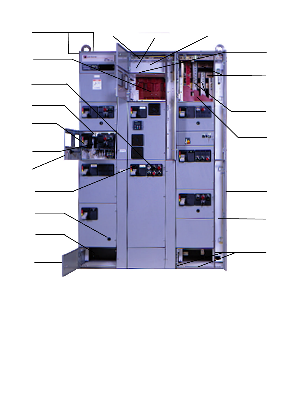
JOINING COMPATIBLE SECTIONS
If two more shipping blocks are to be joined into an
integral assembly, or a section added to an existing
installation, splicing or horizontal bus, ground bus,
neutral bus and joining of the adjacent vertical
sections must be planned with the installation.
1. Remove the side sheets from adjacent vertical
sections to be joined. (These sheets will have
been removed from factory-assembled
sections.)
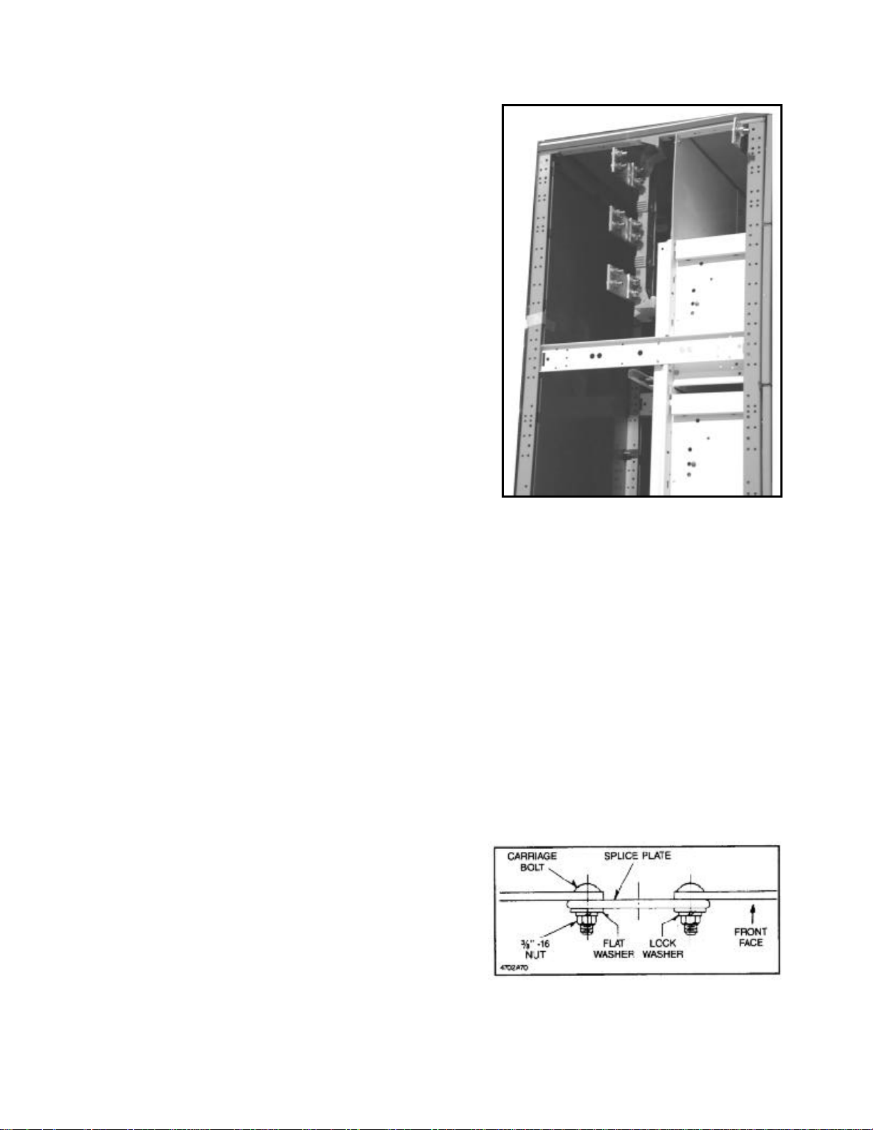
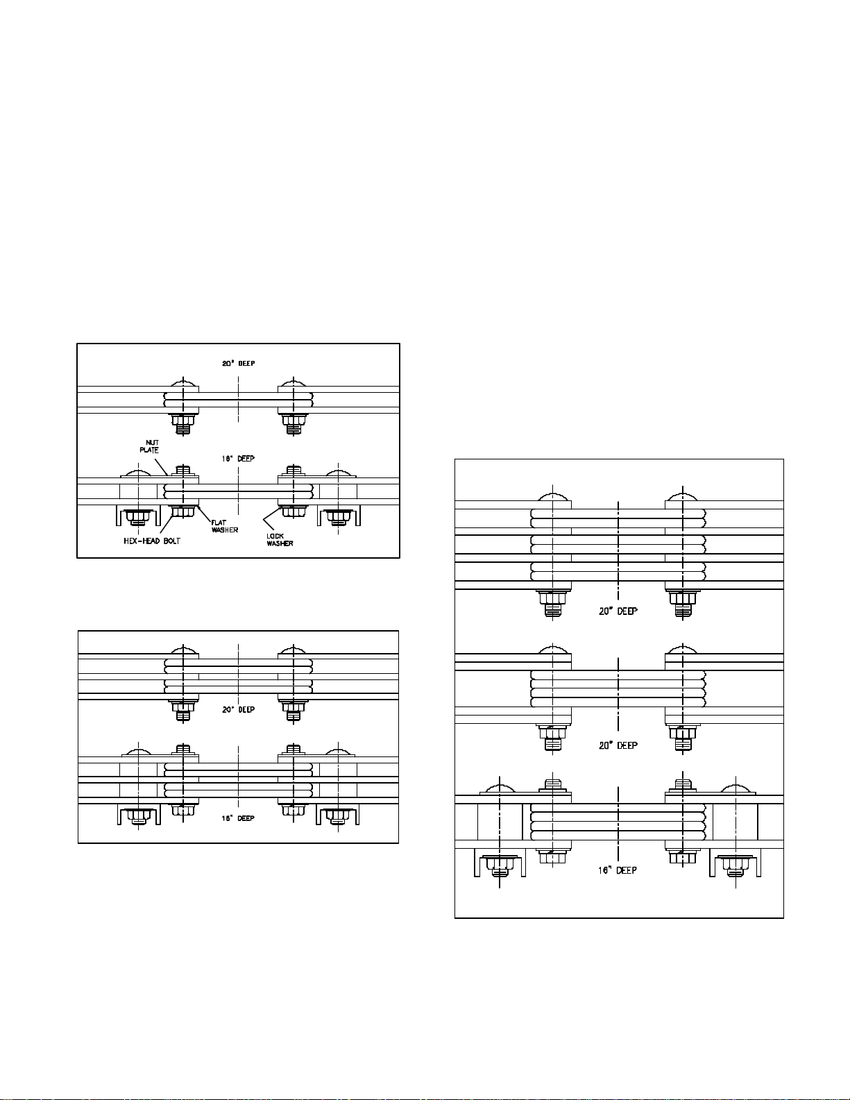
2. The horizontal bus splice plates and connection
hardware will be shipped with the MCC attached
to one end of shipping section. Refer to Figure
4. This method provides the most convenient

7I.B. 8926-1A
access to the bolts, and eliminates the need to
remove the horizontal bus barriers in that
structure. Should the existing bus be oxidized,
sand lightly with a fine aluminum oxide paper.
CAUTION – Do not use emery cloth or any
abrasive containing metal.
3. Remove the upper horizontal wireway door from
the structure on the right side of the left-
hand(LH) section and remove the two-piece
wireway barrier to provide access to the ends of
the bus in that section.
4. Move the section in place, aligning the upright
structural channels and bottom channels.
Alignment of the section with floor sills and
foundation provisions will be facilitated by
removing the bottom horizontal wireway doors.
Using the “U” type frame clamps provided,
clamp adjacent front upright channels together
at the top, bottom and approximate center of the
vertical structure. This operation will be
facilitated by removing the vertical wireway
doors from the left-hand structure and one or
more drawout units from the right-hand
structure. See Part 9.
5. If rear access is available, “U” clamps should
also be used to clamp the rear upright channels
together. In front-mounted-only structures this
will require removal of the adjacent back sheets.
In a back-to-back mounted structure, remove the
vertical wireway doors and one or more drawout
units as above.
6. Secure the sections to the floor sills or mounting
bolts as provided for the installation.
7. Bolt the horizontal bus splice plates to the bus in
the left-hand structure, torquing all bus splice
bolts to 360 pound-inches (30 pound-feet). See
Figure 5.
8. Replace all unit, bus barriers, and doors.
JOINING INCOMPATABLE SECTIONS
Joining a Freedom 2100 Motor Control Center to
other equipment such as Type W and 11-300
Control Centers will usually involve a transition
section, installed between the two varieties of
equipment. This transition section will be detailed on
drawings provided by Cutler-Hammer and the
applicable contact drawings. If provided separately,
it should be installed first. Review the overall
installation task to determine whether the transition
section should be attached to the existing equipment
or to the Freedom 2100 section, before it is moved
into place, and select the sequence which will
provide best access to bus splicing and joining of the
structures.
Figure 4 Splice Plates Attached to RH Section
Figure 6 Single Bar Splice Kit

8I.B. 8926-1A
SPLICE PLATES
Each splice plate kit consists of short pieces of bus
bar the same width as the main horizontal bus of the
MCC the kit is shipped with, four bolts per phase,
and appropriate quantities of related hardware. For a
single bus bar per phase the hardware is used as
shown in Figure 6 for either 16” or 20” deep
enclosures. Each splice plate is punched with
rectangular holes to accept a square shank carriage
bolt that will not rotate as the nut is tightened.
Where the MCC is built with two horizontal bus bars
per phase, the splice plates are installed as shown
in Figure 7. The top edge of Figures 7 through 10
represents the backside of the MCC. The top portion
of each of these figures applies to 20” deep
enclosures and the lower portion to 16” deep
enclosures. Note that for all but the single-bar per
phase (Figure 6) installation, the16” deep enclosures
require the use of a nut plate that is mounted with
the same carriage bolt used to attach the horizontal
bus bars to the channel-shaped insulators. Install
these nut plates before mounting the splice plates.
Tighten the splice plate bolts with a driving torque of
360 pound-inches (30 pound-feet).
Fig. 7 Double Bar Splice Kit
Fig. 8 Triple Bar Splice Kit
TYPE 3R ENCLOSURES
Where the MCC is supplied in a Type 3R enclosure
for an outdoor application, apply roof splice caps at
each shipping block junction to maintain the
enclosure integrity.
Fig. 9 Quadruple Bar Splice Kits

9I.B. 8926-1A
Fig. 10 Six and Eight Bar Splice Kits
JOINING FREEDOM 2100 TO FREEDOM UNITROL OR F10 UNITROL
Consult the assembly instruction supplied with every Freedom 2100 Motor Control Center set up for splice to
Freedom Unitrol or F10 Unitrol.
Fig. 11 Splice Plates Attached to Freedom 2100
Horizontal Bus and Ground Bus at Top. Fig. 12 Horizontal Bus Splice Freedom Unitrol on
Left, Freedom 2100 on Right.

10 I.B. 8926-1A
Fig. 13 Splice Plate Attached to Freedom 2100
Ground Bus at Bottom.
Fig. 14 Splice Plate Attached to Freedom 2100
Neutral Bus.
Part 4
INSTALLING CONDUIT AND WIRING
CONDUIT
Install conduit in such a manner as to prevent water
from entering and accumulating in the conduit or the
enclosure. Eliminate sags in conduit. Have the
conduit enter the motor control center (MCC) in the
areas designated for conduit entry on the plan
views. See pages 31 and 32 of this booklet and
outline drawings shipped with the MCC. Keeping
conduit within the shaded areas shown in the plan
views will avoid cable interference with structural
members and live bus. See Part 12.
WIRING
Install the line and load conductors sized in
accordance with the NEC. Use copper wire only
for control terminations. Use copper wire only
for power terminations unless they are marked
“CU/AL”. Use conductors with a temperature rating
of 75°C or higher, but regardless of the insulation
temperature rating select the wire size on the basis
of 75°C wire ampacity. Using a higher temperature
wire ampacity table often results in a smaller cross-
section of copper available for carrying heat away
from terminals.
Install insulated wire and cable at a temperature
sufficiently warm to prevent the insulation from
cracking or splitting.
When more than one conduit is run from a common
source or to a common load, be sure to have each
conduit carry conductors from each phase and the
same number of conductors per phase. If the phase
conductors are not distributed uniformly, eddy
currents will be generated in the steel between the
conduits.
Locate conductors within the MCC to avoid physical
damage and to avoid overheating. Secure incoming
power lines in a manner adequate to withstand the
forces which will act to separate the conductors
under short-circuit conditions. Use the cable ties
furnished in both horizontal and vertical wireways to
support the load and interconnection wire. Use a
shielded communications cable inside of flexible
metal conduit to protect very low voltage signals
transmitted to or from a computer or programmable
controller.
Lugs furnished with the MCC and its components
are for Class B and Class C stranding. Verify the
compatibility of wire size, type, and stranding with
the lugs furnished. Where they are not compatible,
change the wire or lugs accordingly. If crimp lugs are
used, crimp with the tools recommended by the
manufacturer.
Use care in stripping insulation to avoid nicking or
ringing the metal.
All field wiring to control units should be made in
accordance with the wiring drawings that are
furnished with the control center. Load and control
wiring can be brought in through the upper and/or
lower horizontal wireways. Determine the type of
wiring installed in the control center (NEMA Type B
or C) and proceed per the following appropriate
paragraph.
The phase sequence of the power circuit load
terminals (left-to-right: T1, T2, T3) in units

11 I.B. 8926-1A
mounted on the rear side of the MCC is opposite
to that of the load terminals in units mounted on
the front side of a back-to-back MCC. To obtain
the same direction of rotation for a motor
connected to a rear-mounted unit as for one
connected to a front-mounted unit re-label the
terminals in the rear-mounted unit: T3, T2, T1,
and wire accordingly. Refer to the warning
sticker supplied with rear-side units.
When making connections to the load terminals,
be sure to leave sufficient slack in the wires so
that the unit can be withdrawn to the detent
position for maintenance. See page 20.
NEMA TYPE B WIRING
Each control unit is factory assembled with devices
inter-wired within the unit. In addition, all control
wiring is carried to unit terminal blocks mounted on
the right-hand side of the unit. See Figure 15. Bring
the field wiring of control wires from a horizontal
wireway into the vertical wireway on the right-hand
side of the applicable control unit and terminate
them at the unit terminal blocks. Bring load wiring
from the vertical wireway, under the bottom right-
hand side of the unit, to terminations within the unit.
ENGAGING PULL-APART TERMINAL
BLOCKS
The male portion of the pull-apart terminal block is
located in a plastic bag tied to the pivot rod inside
the unit. This terminal block can be wired outside of
the vertical wireway. To engage the terminal block,
align the fingers of the male connector with the slot
at the back of the female portion of the terminal
block. Then rotate the male portion forward and to
the left into the female portion of the terminal block.
Each male portion of the pull-apart terminal block
has two cavities adjacent to the center terminal
screw to accept the blade of an electrician’s
screwdriver used to cam the block into and out of
engagement. Each male portion also has a rear slot
that can engage the edge of the unit frame where it
can be mounted for ease in trouble-shooting.
NEMA TYPE C WIRING
Each control unit is factory assembled with devices
inter-wired within the unit. In addition, all control
wiring is carried to unit terminal blocks on the side of
the unit and from these unit blocks, along with load
wiring through Size 3, to master terminal blocks
located at the top or bottom of the structure. See
Figure 16. Master terminal blocks can be either fixed
or drawout mounted. In the drawout design the
terminal blocks are rack mounted to permit
withdrawal of the entire assembly for ease of wiring
during installation and maintenance. Bring field
wiring from the horizontal wireway to the master
terminal blocks except for load wiring larger than
Size 3. These latter load wires should be carried into
the vertical wireway and under the bottom right-hand
side of the unit to terminations within the unit.
Fig. 16 Master Terminal Blocks
Fig. 15 Unit Terminal Blocks

12 I.B. 8926-1A
Part 5
INCOMING LINE CONNECTIONS
OVERCURRENT PROTECTION
All ungrounded conductors in a motor control center
(MCC) installation require some form of overcurrent
protection in order to comply with Section 240-20 of
the NEC. Such overcurrent protection for the
incoming lines to the MCC is in the form of fuses or
a circuit breaker located at the transformer
secondary that supplies the MCC. The conductors
from the transformer secondary constitute the feeder
to the MCC, and the “10-foot rule” and the “25-foot
rule” of NEC, 240-21 apply. These latter exceptions
to the general rule allow the disconnect means and
Fig 17 Main Disconnect with Stab Load
Connections
overcurrent protection to be located in the MCC,
provided the feeder taps from the transformer are
sufficiently short and other requirements are met.
MAIN DISCONNECTS
A circuit breaker or a circuit interrupter combined
with fuses controlling the power to the entire MCC
may provide the over-current protection required as
described above or may be a supplementary
disconnect (isolation) means. See Figures 17, 18,
and 19.
Fig. 18 Main Circuit Breaker with Reverse Feed
Fig. 19 Main Circuit Breaker

13 I.B. 8926-1A
When the MCC has a main disconnect, bring the
incoming lines (the feeders) to the line terminals of
the circuit breaker or circuit interrupter. The load side
of the circuit breaker or the load side of the fuses
associated with the circuit interrupter has already
been connected to the MCC bus bar distribution
system. In the case of main disconnects rated 400
amperes or less, this load connection is made by
stab connections to vertical bus bars which connect
to the horizontal bus distribution system. See Figure
17.
INCOMING LINE LUGS
Where the overcurrent protection for the MCC is at a
remote location, the MCC feeder lines are
connected to incoming line lugs attached to the bus
bar distribution system. See Figure 20. For high-
ampere rated horizontal bus bar systems, the
incoming line lugs are mounted on vertical risers,
which connect to the horizontal bus bars. See Figure
21.
SHORT-CIRCUIT BRACING
All incoming lines to either incoming line lugs or to
main disconnects must be braced to withstand the
mechanical forces created by a high fault current.
With the remainder of a Freedom 2100 MCC braed
for not less than 65,000 amperes (rms symmetrical),
the installing electrician needs to anchor the cables
at the incoming line connections sufficiently and
tighten the lugs correctly. Each incoming line
compartment is equipped with a two-piece spreader
bar located about nine inches from the conduit entry.
Use this spreader bar an appropriate lacing material
to tie cables together where they can be bundled
and to hold them apart where they are separated. In
other words, position the incoming line cables and
then anchor them in place. See Figure 22 and the
instruction sheet inside of the MCC.
Fig.20 Incoming Line Lug Connections
Fig. 21 Incoming Line Compartment, 2000A
MAKING CONNECTION
CAUTION: All incoming line compartments
present an obvious hazard when the door is
opened or covers are removed with power on.
When working in this area, the incoming feeder
should be de-energized.
Before beginning work on incoming line connections,
refer to all drawings furnished by Cutler Hammer as
well as all applicable contract drawings for the
particular installation.
Depending on the location, size and type of the
incoming arrangement, remove one or more
horizontal and vertical wireway doors, and selected
units to provide complete access. See Part 9 for unit
removal instructions.
For top entry, the top cover plates are easily
removed for drilling or punching operations.
Fig. 22 Spreader Bar For Top Entry

14 I.B. 8926-1A
Part 6
OVERCURRENT PROTECTION DEVICES
DEVICE SELECTION
Articles 240 and 430 of the NEC contain the rules for
selecting fuses, circuit breakers and overload relays
by type and by voltage and ampere rating. Follow
these rules for feeder circuits, and the instructions
attached to the inside of the left-most vertical
wireway door, for motor branch circuits. Select and
install overload relay current elements (heaters)
based on the motor service factor and full-load
current. Ambient compensated overload relays are
used in motor control centers (MCC’s) to offset the
temperature gradient which occurs from top to
bottom in a loaded vertical section.
HEATERS MUST BE INSTALLED IN THE
STARTER OVERLOAD RELAY ASSEMBLIES
BEFORE THE STARTER IS ENERGIZED.
C306 THERMAL OVERLOAD RELAYS (FIG.24)
C306 Overload Relays are provided on Freedom
Starters. Four sizes are available for overload
protection up to 114 amperes. Features include:
•Selectable Manual or Automatic Reset operation.
•Interchangeable Heater Packs adjustable ±24%
to match motor FLA and calibrated for use with
1.0 and 1.15 service factor motors.
Heater packs for 32 ampere overload relay will
mount in 75 ampere overload relay – useful in de-
rating applications such as jogging.
•Class 10 or 20 heater packs. (Fig. 24) Use Class
10 heaters with fusible or thermal magnetic
breaker disconnects only.
•Bimetallic, ambient compensated operated. Trip
free mechanism.
•Electrically isolated NO – NC contacts (pull
RESET button to test).
•Overload trip indication.
•Single phase protection.
•UL listed, CSA certified and NEMA compliance.
Fig. 23 Overload Relay Settings
Fig. 24 C306 Thermal Overload Relay and Heater
Pack.
C306 OVERLOAD RELAY SETTING
FLA DIAL ADJUSTMENT – For motors having a
1.15 service factor, rotate the FLA adjustment dial to
correspond to the motor’s FLA rating. Estimate the
dial position when the motor FLA falls between two
letter values as shown in Fig. 23.
For motors having a 1.0 service factor, rotate the
FLA dial one-half position counterclockwise (CCW).
MANUAL/AUTOMATIC RESET – The overload relay
is factory set “M” for manual reset operation as
shown in Fig. 23. For automatic reset operation, turn
the reset adjustment dial to the “A” position.
Automatic reset is not intended to two-wire devices.
TEST FOR TRIP INDICATION – To test overload
relay for trip indication when in manual reset, pull out
the blue reset button. An orange flag will appear
indicating that the device has tripped. Push reset
button to reset.
WARNING – To provide continued protection
against fire or shock hazard, the complete overload
relay must be replaced if burnout of the heater
element occurs.

15 I.B. 8926-1A
CURRENT TRANSFORMERS
When current transformers are used with overload
relays, the current through the overload relay heater
is related to the motor full-load by the inverse of the
current transformer ratio.
WARNING: Do not ever remove heaters from Size 5
and larger starters to check unit operation. These
starters use current transformers to drop the current
to the range of the size 1 overload relay. Operation
with heaters removed will not interrupt voltage to the
motor and will generate dangerous voltages in the
open secondary of the current transformer.
MOTOR CIRCUIT PROTECTOR (HMCP)
AFTER INSTALLATION OF THE CONTROL
CENTER, EACH MCP MUST BE ADJUSTED TO
ACTUAL MOTOR FULL-LOAD AMPERES (FLA) SO
THAT IT WILL TRIP AT ANY CURRENT WHICH
EXCEEDS STARTING INRUSH. This setting
provides low-level fault protection. The first half-
cycle inrush will vary with the motor characteristics.
Motors with locked-rotor currents of six times motor
full-load amperes will usually require an
instantaneous magnetic setting of 7 to 11 times
motor full-load amperes to prevent tripping when
starting.
Fig. 25 HMCP Magnetic Adjustment
A cam to accept a small narrow-blade electrician’s
screwdriver is near the lower left corner and around
which are eight lettered adjustment points, calibrated
in trip amperes. See Figure 25. Adjustment should
never exceed 13 times FLA which is in accordance
with NEC requirements for magnetic-trip-only
breakers. Adjustment should be made as follows:
1. Obtain FLA from motor nameplate.
2. Multiply FLA by 13.
3. Set the cam to the highest trip setting which does
not exceed the calculated figure of Item 2. This is
the maximum setting that should be used.
4. Depress and turn the screwdriver adjustment
counter-clockwise one setting at a time, until the
breaker trips in starting and then adjust upward
one setting position. This will insure that the
circuit will open instantly on any current above
the motor inrush, usually 7 to 11 time FLA.
The PUSH-TO-TRIP button checks the tripping
function and is used to periodically exercise the
operating mechanism. The button is designed to be
operated by using a small screwdriver.
Freedom 2100 MCC’s are supplied with Type HMCP
motor circuit protectors having an interrupting rating
to match the short-circuit withstand rating of the bus
bar system. For HMCP’s in 225, 400, and 600
ampere frame sizes, the magnetic-trip adjustment is
set for each pole. A three-pole HMCP has three trip
settings to adjust. Place all three poles at the same
setting.
CURRENT LIMITERS FOR USE WITH TYPE
HMCP AND FD BREAKERS
The addition of the current limiter provides
interrupting capacity above the range handled by the
HMCP in motor starters or by FD thermal-magnetic
feeder breakers.
Each HMCP or FD breaker rated up to 150 amps
has its own current limiter to provide coordinated
protection against faults up to 100,000 amperes, rms
symmetrical.
Built-in trip indicators in each phase immediately
show when a fault has blown the current limiter and
tripped the circuit breaker. This provides protection
against single phasing. After interrupting a fault,
the current limiter will require replacement. After
the fault has been cleared, the current limiter is
replaced by the removal of three screws. The
breaker can then be reset to provide for subsequent
high overcurrent protection.

16 I.B. 8926-1A
TYPE HMCP AND FD CIRCUIT BREAKERS
WITH TERMINAL END COVERS
Circuit breakers installed in units connected to 600
volt distribution systems require a terminal end cap
to be installed on the line side. Replace the terminal
end cap when replacing circuit breakers in such
units.
Part 7
OVERLOAD RELAY HEATER SELECTION
HEATER SELECTION AND INSTALLATION
Heaters should be selected on the basis of the
actual full load current and service factor as shown
on the motor nameplate or in the motor
manufacturer’s published literature.
When motor and overload relay are in the same
ambient and the service factor of the motor is 1.15 to
1.25, select heaters and set FLA adjustment dial
from the heater application table. If the service
factor of the motor is 1.0, or there is no service
factor shown, rotate the FLA adjustment dial
counter-clockwise one half (1/2) position.
The conductors attached to the terminals of an
overload relay act as a heat sink and are a
consideration in establishing the current rating of
each heater element. To prevent nuisance tripping,
which will occur if undersized conductors are used,
select the wire size as if the conductors had an
insulation temperature rating of 75°C, even if the
conductors actually used have a temperature rating
higher than 75°C.
Protect heater and starter against short circuits by
providing branch circuit protection in accordance
with the National Electric Code.
Note: Before installing heater packs, refer to the
motor nameplate for FLA (full load amps) and
service factor (1.5 or 1.0). Select the heater pack
from the proper table on this page.
To install:
A. Insert three (3) identically numbered heater packs
into the overload relay with an FLA rating that
includes the motor nameplate FLA (full load
amps).
B. Tighten the heater pack mounting screws
securely per recommended torque values listed
below.
Heater Pack Numbers Recommended Torque
H2001B thru H2017B
H2018 thru H2024 9 lb-in [1 N•m]
24-30 lb-in [2.7-3.4 N•m]
C. Adjust the FLA adjustment dial to
the motor nameplate FLA (full
load amps).
THE OVERLOAD IS NOW SET FOR
1.15 SERVICE FACTOR.
D. If the motor nameplate is 1.0
service factor, rotate the FLA
Adjustment dial counter-clockwise
on half (1/2) position.
E. The overload is factory set for M
(MANUAL) reset operation. If
automatic reset is required, turn
the reset adjustment dial to A
(AUTO). Automatic reset is not
intended for two-wire control
devices.
Heater Pack
Mounting Screw

17 I.B. 8926-1A
TO REMOVE HEATER PACKS
Loosen two (2) heater packs mounting screws and
remove heater pack from overload relay.
OVERLOAD RELAY SETTING
This bimetalic ambient compensated overload relay
is adjustable within the FLA range of the heater
pack. Each heater pack is marked with its FLA
ratings. With proper heater section, the overload
relay will ultimately trip at 125% FLA for a 1.15
service factor motor and at 115% FLA for a 1.0
service factor motor.
HEATER SELECTION / INSTALLATION
Select the appropriate heater pack number, which
corresponds to the motor FLA rating for your
application. Insert each heater into the overload
relay and tighten heater mounting screws securely
per table below.
NOTE: A total of three individual heaters must be
installed in order for the overload relay to work
properly.
HEATER PACK NOS. TORQUE
H2001B thru H2017B 9 lb-in.
H2018 thru H2024 4-30 lb-in.
FLA DIAL ADJUSTMENT
For motors having a 1.15 service factor, rotate the
FLA adjustment dial to correspond to the motor’s
FLA rating. Estimate the dial position when the
motor FLA falls between two letter values as shown
in the example.
For motors having 1.0 service factor, rotate the FLA
dial one-half position counter-clockwise (CCW).
FLA 1.0
ADJUSTMENT SERVICE
DIAL FACTOR
Example of a 12.0 FLA setting for a
heater pack number H2011B
showing position for 1.0 or 1.15
service factor motor.
MANUAL / AUTOMATIC RESET
The overload relay is factory set at “M” for manual
reset operation as shown in the illustration. For
automatic reset operation, turn the reset adjustment
dial to the “A” position
Automatic reset is not intended for two-wire control
devices.
RESET Examples of
ADJUSTMENT setting for
DIAL manual reset.
TEST FOR TRIP INDICATION
To test overload relay for trip indication when in
manual reset, pull out the blue reset button. An
orange flag will appear indicating that the device has
tripped. Push reset button in to reset.
A B C D
.254 .306 .359 .411 H2001B
.375 .452 .530 .607 H2002B
.560 .676 .791 .907 H2003B
.814 .983 1.15 1.32 H2004B
1.20 1.45 1.71 1.96 H2005B
1.79 2.16 2.53 2.90 H2006B
2.15 2.60 3.04 3.49 H2007B
3.23 3.90 4.56 5.23 H2008B
4.55 5.50 6.45 7.40 H2009B
6.75 8.17 9.58 11.00 H2010B
9.14 10.8 12.4 14.0 H2011B
14.0 16.9 19.9 22.8 H2012B
18.7 22.7 26.7 30.7 H2013B
23.5
28.5
33.5
-
H2014B
FLA DIAL POSITIONS
STD TRIP
CLASS 20
NEMA SIZE 0 AND 1 SIZE F
HEATER PACK SELECTION TABLE
MOTOR FLA RATING
NEMA SIZE AMPERES SIZE AMPERES
018
1
27
F
32
MAXIMUM RATINGS
Use 75°C copper conductors only
Max. Wire Size – 8 AWG
nNOTE: After the above referenced settings have
been made, rotate the FLA dial one position
clockwise for these heaters (see table). If less than
one position is available, rotate dial maximum. This
note does not apply when these heaters are used
with adapter base. Catalog No. C306TB1.
Exception: does not apply to AN16DN0.
WARNING – To provide continued protection against
fire or shock hazard, the complete overload relay
must be replaced if burnout of the heater element
occurs.

18 I.B. 8926-1A
SIZE J AND K
A B C D
3.23 3.90 4.56 5.23 H2008B
4.55 5.50 6.45 7.40 H2009B
6.75 8.17 9.58 11.0 H2010B
9.14 10.8 12.4 14.0 H2011B
14.0 16.9 19.9 22.8 H2012B
18.7 22.7 26.7 30.7 H2013B
23.5 28.5 33.5 38.5 H2014B
29.0 34.0 39.1 44.1 H2015B
39.6 45.5 51.5 57.4 H2016B
53.9
60.9
67.9
74.9
H2017B
NEMA SIZE 2
STD TRIP
Class 20
HEATER PACK SELECTION TABLE
MOTOR FLA RATING
FLA DIAL POSTITIONS
NEMA SIZE
AMPERES SIZE AMPERES
245 J60
K
73
MAXIMUM RATINGS
Use 75°C copper conductors only
Max. Wire Size – 3 AWG
lNOTE: After the above reference settings have
been made, rotate the FLA dial one position
clockwise for these heaters (see table). If less than
one position is available, rotate dial to maximum.
This note does not apply when these heaters are
used with adapter base. Catalog No. C306TB1.
SIZE N
A B C D
18.0 20.2 22.3 24.5 H2018
24.6 27.6 30.5 33.4 H2019
33.5 37.5 41.5 45.6 H2020
45.7 51.2 56.7 62.1 H2021
62.2 69.7 77.1 84.6 H2022
84.7 94.9 105 115 H2023
106
118
131
144
H2024
NEMA SIZE 3 AND 4
HEATER PACK SELECTION TABLE
STD TRIP
Class 20
MOTOR FLA RATING
FLA DIAL POSTITIONS
NEMA SIZE AMPERES SIZE AMPERES
390 N* 14
4*
135
MAXIMUM RATINGS
Minimum Wire Size – 6 AWG
lNOTES:
Part Winding Starters – Select heater packs for
50% of the motor FLA
Wye Delta Starters – Select heater packs for 58%
motor FLA
uFor motor FLA values not listed, turn the dial
clockwise for higher or counterclockwise for
lower ratings.
A B C D
34 41 48 54 H2003B
49 59 69 79 H2004B
72 87 103 118 H2005B
107 130 152 174 H2006B
129 156 182 209 H2007B
194
234
274
-
H2008B
STD TRIP
Class 20
NEMA SIZE 5
HEATER PACK SELECTION TABLE
MOTOR FLA RATING
FLA DIAL POSTITIONS
MAXIMUM RATINGS
NEMA Size 5 = 270 Amperes Min. Wire Size-2 AWG
A B C D
144 174 205 235 H2005B
215 259 304 348 H2006B
258 312 365 419 H2007B
388
468
547
-
H2008B
STDTRIP
Class 20
NEMA SIZE 6
HEATER PACK SELECTION TABLE
MOTOR FLA RATING
FLA DIAL POSTITIONS
MAXIMUM RATINGS
NEMA Size 6 = 540 Amperes
sFLA rating marked on heater pack multiplied
by a transformation ratio. For motor FLA values
not listed, turn the dial clockwise for higher or
counterclockwise for lower ratings.
Autotransformer F600 1 3
Part-Winding F700 .5 6
Star-Delta
F800
0 .575
3
Magnetic Reduced Voltage Starter Classes F600, F700,
F890 with C306 Thermal Overload Relay.
Qty. of
heaters
required
per starter
Multiply actual
motor full load
current by factor
below and refer
to adjusted full
load current
column in tables.
Class
Starter Type

19 I.B. 8926-1A
Part 8
INSPECTION PRIOR TO ENERGIZING
1. Before energizing the motor control center
(MCC), conduct a thorough inspection to make
certain that all foreign materials such as tools,
scraps of wire and other debris are removed
from all units and the structure. Remove any
accumulation of dust and dirt with a vacuum
cleaner.
2. All circuit connections are tightened at time of
assembly by power-driven tools with controlled
torque. However, the vibrations experienced in
transit may loosen some of these connections.
Check at least 10% of the total connections for a
tight connection. Should this spot-check
reveal some loose connections, it will be
necessary to check all connection points.
The connections to be checked include bus
hardware, circuit breaker and switch terminals,
contactor and relay terminals and terminal
blocks. Always check the incoming line
connections. Tighten to the torque values shown
in Tables 8-1.
3. Remove all blocks or other temporary holding
means used for shipment from all component
devices in the MCC interior.
4. Check the enclosure to see that it has not been
damaged so as to reduce electrical spacings.
5. Compare all circuits for agreement with the
wiring diagrams which accompany the MCC. Be
sure that each motor is connected to its intended
starter.
6. Make certain that field wiring is clear of live
busses and physically secured to withstand the
effects of fault current.
7. Check to determine that all grounding
connections are made properly.
8. Check all devices for damage. Make all
necessary repairs or replacements, prior to
energizing.
9. Manually exercise all switches, circuit breakers,
and other operating mechanisms to make
certain that they are properly aligned and
operate freely.
10. Test any ground-fault protection systems that
were furnished.
11. Set any adjustable current and voltage trip
mechanisms to the proper values.
12. Ensure that overload relay heater elements are
installed and selected to the full-load current
shown on the nameplate of each motor.
13. Install power circuit fuses in the fusible switches
in accordance with NEC application
requirements. Make sure that fuses are
completely inserted in the clips provided. Do not
attempt to defeat the rejection feature on the
fuse clip, when provided.
14. Do not operate a current transformer with its
secondary circuit open. Insure current
transformer is connected to a load, or a
secondary shorting bar is installed.
15. To prevent possible damage to equipment or
injury to personnel, check to insure that all parts
and barriers that may have been removed
during wiring and installation have been properly
reinstalled.
Coil Leads…………………………………………….
…….8 lb.-in.
Relays……………………………………………………
…….8 lb.-in.
Push Buttons………………………………………..
…….8 lb.-in.
Control Fuse Blocks……………………………………
…….8 lb.-in.
Auxiliary Contacts……………………………………
…….8 lb.-in.
Control Wiring Terminal Blocks
Side Mounted Lug/Compression…………………
…....9 lb.-in.
Rail Mounted Lug Type…………………………….
…...12 lb.-in.
Rail Mounted Compression Type………………….
…...18 lb.-in.
Using Overload
Catalog Number
Conductors
C306DN3 Wire size (AWG) Torque (lb.-in.)
14-10 35
840
6 - 4 45
3 - 2 50
For Starters Wire size (AWG) Torque (lb.-in.)
840
6 - 4 45
3 - 2 50
Socket Size (In.) Torque (lb.-in.)
3/16 120
1/4 200
5/16 250
Size N and Size 4
Size 5 and Size 6
30 Amp Fuse Assy………………………………… ……25 lb.-in.
60 Amp Fuse Assy………………………………… ……50 lb.-in.
100 Amp Fuse Assy…………………………………
……50 lb.-in.
200 Amp Fuse Assy………………………………. …..300 lb.-in.
400 Amp Fuse Assy………………………………. …..300 lb.-in.
600 Amp Fuse Assy………………………………. …..300 lb.-in.
#2/0-350 MCM…………………………………….. …..360 lb.-in.
#2/0-650 MCM…………………………………….. …..360 lb.-in.
#2/0-750 MCM…………………………………….. …..500 lb.-in.
500-1000 MCM…………………………………….. …..600 lb.-in.
All………………………………….. ………….275 lb.-in.(23lb.-ft.)
20 lb.-in.
BREAKERS-
Refer to Torque Values on Breaker Case
Incoming Line Lugs:
Bus Bolts:
Size 3
Socket Head Screw
275 lb.-in.
500 lb.-in.
Use 75
Degrees C
copper or
aluminum
conductors
Slotted Head Screw
Fused Switches:
TABLE 8-1 DRIVING TORQUE
Control Wiring:
Power Wiring: Starters
C306GN3 and
size 2 Contactor
Tightening Torque - Load Side
Use 75
Degrees C
copper
conductors

20 I.B. 8926-1A
16. Conduct an electrical insulation resistance test to
make sure that the MCC and field wiring are free
from short circuits and grounds. Do this test
phase-to-phase, phase-to-ground, and phase-to-
neutral, with the switches or circuit breakers
opened.
17. If the MCC contains a labyrinth vertical bus
barrier system, verify the operation of the
automatic shutters. See Part 9 for adjustments
of this mechanism.
18. Install covers, close doors, and make certain that
no wires are pinched and that all enclosure parts
are properly aligned and tightened.
19. Turn all circuit breakers and fusible switches to
the OFF position before energizing the bus.
Part 9
UNIT INSTALLATION AND ADJUSTMENT
DOOR REMOVAL AND INSTALLATION
All doors on the control center are mounted on pin
hinges to facilitate removal for installation and
maintenance operations. With the operating handle
on the OFF position, rotate the quarter-turn latches,
open the door, remove the hinge pins as shown in
Figure 26, partially close the door and lift it from the
structure. Reverse this procedure for installation.
UNIT REMOVAL AND INSTALLATION
After opening and/or removing the unit door, the
control unit is exposed. With a screwdriver, push in
on the latch at the top center of the unit and rotate ¼
turn counterclockwise. CAUTION: Units 18” or more
high have a retaining brace at the lower edge of
each side of the unit frame to add stability in
shipping. The shipping braces may be retained or
removed after installation; unscrew prior to unit
withdrawal. Pull-apart terminal blocks in the vertical
wireway must be disengaged (see Figure 27 and
page 10) and wiring from the unit to other units, to
master terminal blocks or to load devices must be
disconnected before the unit is removed. Grasp the
unit as shown in Figure 28 and pull it outward. The
first inch of travel pulls the stabs free from the
vertical bus, and the grounding clip on the side of
the unit frame is also disengaged.
To replace a control unit, position the mounting
points on the unit frame with the mating guide rails.
Slide the unit inward until all four mounting points
are engaged, then move it inward with a quick push.
This movement easily overcomes the compression
of the stabs as they engage the vertical bus. With
the unit in its correct position, the quarter-turn latch
is easily engaged by pushing inward and rotating ¼
turn clockwise.
Fig.26 Hinge Pin Removal
Fig. 27 Disengaging Pull-Apart Terminal Blocks
Fig. 28 Withdrawing a Unit
Table of contents
Other Cutler-Hammer Control Unit manuals