manuals.online logo
Brands
  1. Home
  2. •
  3. Brands
  4. •
  5. Cutler-Hammer
  6. •
  7. Control Unit
  8. •
  9. Cutler-Hammer 8280A User manual

Cutler-Hammer 8280A User manual

104232 Rev 02Cutler-Hammer
Instruction Manual—80 Series Photoelectric
8280A Time Delay Logic Card
INTRODUCTION
The 8280A is an optional logic card for the 80 Series “Blue
Eyes” Control Modules. The 8280A provides three ranges of
independently adjustable on and off delay.
By themselves, the control modules provide a simple on-off
control action through either a triac output or NPN transistor.
Control actions take many forms; start up and shut down
sequences, counting, sorting, or jam detection are some of the
possibilities. The on-off state of the control module’s output
depends on the status of the infrared light beam established by
a sensor head. The light beam is either complete (LT) or
blocked(DRK).
The addition of time delay to a control module’s operation
separates the instant of the LT/DRK change from the start of
the control action. Time delay makes it possible for the control
module to ignore short duration LT/DRK changes and/or to
stretch the apparent length of a LT/DRK change.
INSTALLATION
1. Remove the sensor head if installed.
2. Remove the pin guide.
3. Set the appropriate switches for the timing range desired.
4. Orient the logic card so that the adjustment
potentiometer(s) face out.
5. Slide the logic card all the way into the control module and
replace or install the sensor head. Be sure that the sensor
module’s bayonet pins line up properly with the logic
card’s receptacles. The logic card is connected to the
control module’s circuit only when the sensor head is
plugged in.
6. Adjustment within the timing range selected can now be
made via the potentiometer(s) on the logic card.
SPECIFICATIONS
Input Power:
Supplied only by the 80 Series Control Modules; do not
connect the one-shot card to external power.
Timing Range:
5 mS to 20 seconds in three ranges:
Range 1 ...........................................10 mS to 200 mS
Range 2 .................................... 100 mS to 2.5 seconds
Range 3 ..................................... 1.0 mS to 20 seconds
Power Up Initialization:
Time delay settings are disabled for 20 mS on power up. The
8280A assumes the control modules settings and beam status.
Note- For all Series 80 control modules, the output(s) are
inactive (open) for 100 to 300 mS after power is applied
regardless of control settings or the light beam’s status.
Environmental:
Operating Temperature............... -40° to 131°F (-40° to 55° C)
Storage Temperature ................. -40° to 167° F (-40° to 75° C)
Operating Humidity...............................95% Relative Humidity
Storage Humidity .........................95% Relative Humidity, Max.
Mechanical:
Construction - The 8280A consists of a single PCB assembly
configured to interface with the Series 80 sensor system.
Vibration - 5 G or 0.06 inch displacement, whichever is less,
over a frequency range of 10 Hz to 2000 Hz
6
5
Potentiometers
This side in
Range Switches
Effective 5/20/97
Printed in U.S.A.
104232 Rev 02
Cutler-Hammer
720 80th Street SW
Everett, WA 98203-6299
425/513-5300 Fax: 425/513-5302
www.cutlerhammer.eaton.com
Page 2
Still Need Help?
Contact the
Cutler-HammerSensor
Application Engineers
1-800-426-9184
Fax: 425-513-5356
TIMINGDIAGRAM:
Condition 1 - DRK delay prevents the output from changing at
the same moment the beam is blocked (DRK).
Condition 2 - LT delay prevents the output from changing at
the same moment the beam is completed (LT).
CONTROLSANDADJUSTMENTS
The timing range is switch selected according to the selection
chart printed on the label. Paste the label on the inside of the
control module’s side cover for future reference. The length of
time delay may be varied, within the range selected, by
adjusting the pulse width potentiometer (clockwise = increase).
The selected timing range applies to both LT and DRK delay.
Slide the numbered switch upward for the “ON” position. In the
example below, 1 and 2 are set to “ON,” and 3 is “OFF.”
INCR
LT
DELAY DRK
DELAY
8280A
TIME DELAY
RANGE (SEC)
.01 - .20
.10 - 2.0
1.0 - 20
SWITCH
1
ON
ON
ON
2
OFF
ON
ON
3
OFF
OFF
ON
With the installation of a logic card, the control module’s
output is governed by the settings of the logic card rather
than the status of the infrared light beam. For the following
timing diagrams, assume that the control module is set for LT
mode operation (beam complete = output on); DRK mode
operation is similar.
Condition 3 - LT and DRK delay can be used together to offset
the output action.
Condition 4 -An event which is shorter than the set delay
period will be ignored and the delay reset.

Other Cutler-Hammer Control Unit manuals

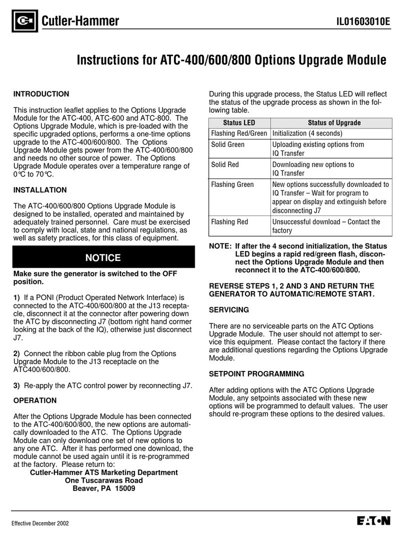
Cutler-Hammer ATC-400 User manual

Cutler-Hammer

Cutler-Hammer ATC-400 User manual

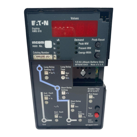
Cutler-Hammer Digitrip RMS 810 User manual

Cutler-Hammer

Cutler-Hammer Digitrip RMS 810 User manual

Cutler-Hammer Freedom 2100 Series Manual

Cutler-Hammer

Cutler-Hammer Freedom 2100 Series Manual

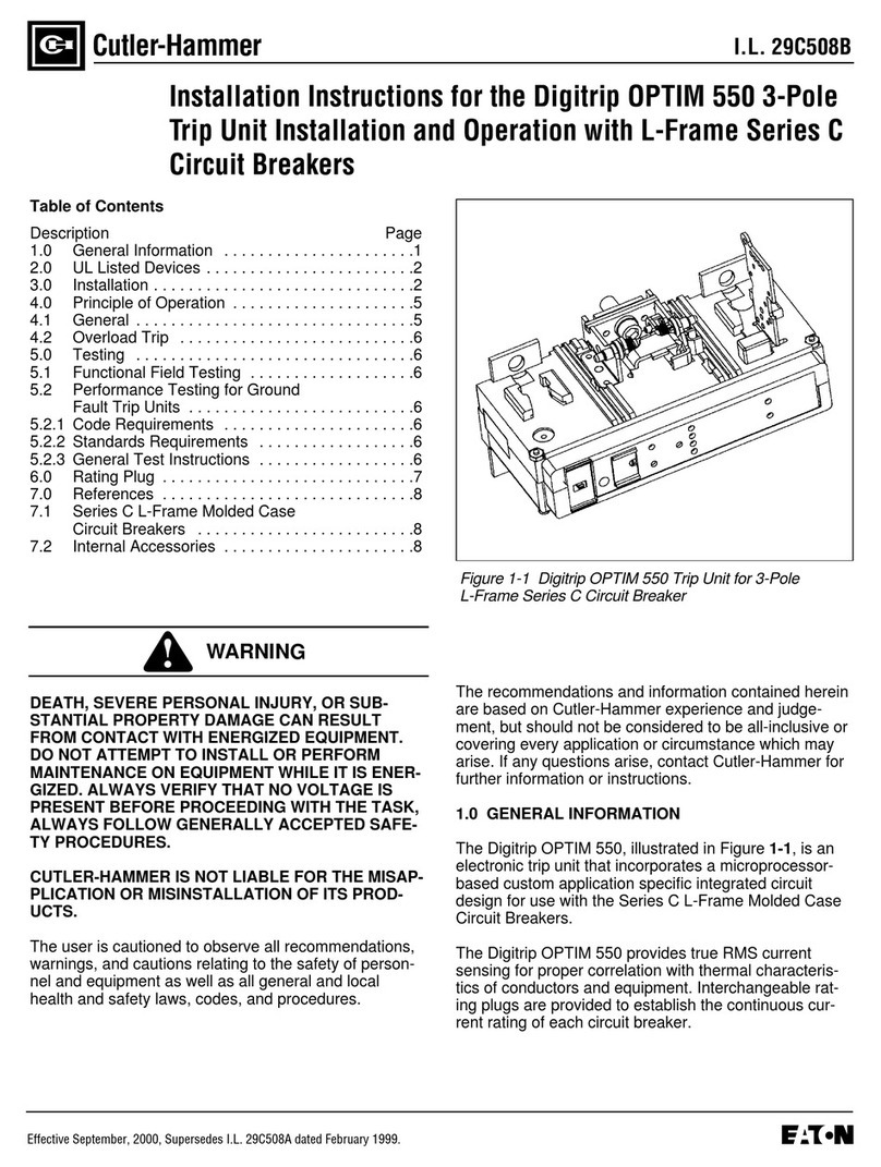
Cutler-Hammer Digitrip OPTIM 550 User manual

Cutler-Hammer

Cutler-Hammer Digitrip OPTIM 550 User manual

Popular Control Unit manuals by other brands

Fukuda Denshi HR-800 Service manual

Fukuda Denshi

Fukuda Denshi HR-800 Service manual

Burkert 6440 operating instructions

Burkert

Burkert 6440 operating instructions

Beckhoff EtherCAT Box quick start guide

Beckhoff

Beckhoff EtherCAT Box quick start guide

Graco SDM8 Series instructions

Graco

Graco SDM8 Series instructions

Honeywell W7212 Product data

Honeywell

Honeywell W7212 Product data

Gemini Valve 89 Series installation instructions

Gemini Valve

Gemini Valve 89 Series installation instructions

Allen-Bradley ControlNet 1786-RPCD installation instructions

Allen-Bradley

Allen-Bradley ControlNet 1786-RPCD installation instructions

Fermax AMPLIFIER MODULE CITYMAX quick start guide

Fermax

Fermax AMPLIFIER MODULE CITYMAX quick start guide

SHEN JIZHUO TECHNOLOGY JZ861 user manual

SHEN JIZHUO TECHNOLOGY

SHEN JIZHUO TECHNOLOGY JZ861 user manual

DeZurik APCO CSD-800 user manual

DeZurik

DeZurik APCO CSD-800 user manual

Technische Alternative ESR 31 Operation & installation instructions

Technische Alternative

Technische Alternative ESR 31 Operation & installation instructions

Ogden ETR-9040 instruction manual

Ogden

Ogden ETR-9040 instruction manual

Navilock NL-82052RS manual

Navilock

Navilock NL-82052RS manual

M-system R3-GC1 instruction manual

M-system

M-system R3-GC1 instruction manual

ABB NMBP-01 Installation and startup guide

ABB

ABB NMBP-01 Installation and startup guide

Watts FlowBox HKF25 Series Installation and operating manual

Watts

Watts FlowBox HKF25 Series Installation and operating manual

Jung 4091 TSM manual

Jung

Jung 4091 TSM manual

Pfeiffer Vacuum UVH 016 VI operating instructions

Pfeiffer Vacuum

Pfeiffer Vacuum UVH 016 VI operating instructions

manuals.online logo
manuals.online logoBrands
  • About & Mission
  • Contact us
  • Privacy Policy
  • Terms and Conditions

Copyright 2025 Manuals.Online. All Rights Reserved.