Cutler-Hammer CLIPPER VL Installation instructions

Cutler-Hammer - The Industry Leader in Power Protection CVL
TD.37B.05.T.E. - 1 - IM-PX1-00009-1 04.00 Rev. H
CLIPPER VL
INSTALLATION & OPERATING
MANUAL

Cutler-Hammer - The Industry Leader in Power Protection CVL
TD.37B.05.T.E. - 2 - IM-PX1-00009-1 04.00 Rev. H
CLIPPER VL
INSTALLATION & OPERATING MANUAL
This manual applies to all Clipper VL Nema 1,
Nema 3R and Flush mount versions.
1.0 Introduction
Congratulations on your purchase of this Surge
Protective Device (SPD). The Clipper VL is a SPD that
protects sensitive electronic equipment from damaging
transients, surges and electrical line noise. Proper
installation is critical to ensure this unit operates as
intended.
Please read the installation and operating instructions
prior to using this SPD.
2.0 Preparation
2.1 Verify that the electrical distribution system voltage
and wiring configuration are the same as that of the
enclosed SPD by checking the voltage-rating label
located on the inside cover.
2.2 Check the facility grounding system. All
grounding, bonding and earthing practices must meet
NEC, CEC and local approved practices. A poor
ground, or grounding/bonding violations, seriously
affect the SPD's ability to function as specified.
3.0 Installation Procedures
The CVL uses 14 AWG wire for connection to the
distribution system. The wires require protection from
a 15 Amp circuit breaker or fuse. This ensures
protection against fault current and fire. The CVL must
be connected in accordance with NEC/CEC and local
codes for all safety ratings.
3.1 Locate an available 15 AMP breaker space
immediately after the main breaker in the electrical
equipment being protected. If this position is not available,
identify the next closest breaker space. Note that fuses
rated 600V, 15 AMP can be used in place of the circuit
breaker described here.
3.2 If there is no space available within the electrical
equipment, locate the closest existing 15 AMP breaker
within the electrical equipment.
3.3 To ensure maximum effectiveness and provide the best
possible protection for the sensitive electrical equipment,
the SPD must be installed as close to the electrical
equipment as possible.
The 14 AWG wire lead length between the SPD and
installation breaker should be 35 cm (14”) or less.
NOTE: Twist the wires tightly together. Minimize overall
lead length to optimize SPD performance.
3.4 Turn OFF the power to the electrical equipment where
the SPD is to be installed.
3.5 Install a 15 AMP branch circuit breaker to feed the SPD
(if space is not available refer to 3.2).
3.6 The Clipper VL may be installed using a standard
knockout. If so, remove lock-nut from nipple, insert nipple
and 14 AWG wires through knockout, re-install lock-nut
and tighten. If not installed directly into the electrical
equipment use a metal conduit (rigid or flexible) between
the SPD and the electrical equipment. For NEMA 3R
applications use watertight conduit and glands, and ensure
the Clipper VL is mounted with the nipple pointing in the
downward direction and the driphood in the upright
direction.
3.7 Run the 14 AWG wires from the SPD to the electrical
equipment.
3.8 Strip the ends of the wires and terminate at the line
side terminals of the identified branch breaker mounted
within the electrical equipment. Tighten all connections.
CVL Nema 3R
CVL Nema 1

Cutler-Hammer - The Industry Leader in Power Protection CVL
TD.37B.05.T.E. - 3 - IM-PX1-00009-1 04.00 Rev. H
3.9 Recheck all connections.
3.10 Switch the MAIN power to the ON position for the
electrical equipment and SPD.
3.11 Check all status indicator lamps to verify system
operation (see maintenance and operating procedures).
3.12 If a remote monitoring option is required, connect the
Form C Contacts to an alarm or building monitoring system.
These relay contacts are rated at:
AC - 125 V, 60 VA, 1 Amp.
DC - 150 V, 30 W, 1 Amp.
Figure 1: Clipper VL Wiring Examples
POWER WIRE COLOR CODE FORM C WIRE COLOR CODE
MODE CVL MODE COLOR
L1 (A) BLACK COMMON BLUE/WHITE
L2 (B) RED NORMALLY OPEN RED/WHITE
L3 (C) BLUE NORMALLY CLOSED ORANGE/WHITE
NEUTRAL WHITE
GROUND/PE GREEN/YELLOW
Normal condition is powered with no faults

Cutler-Hammer - The Industry Leader in Power Protection CVL
TD.37B.05.T.E. - 4 - IM-PX1-00009-1 04.00 Rev. H
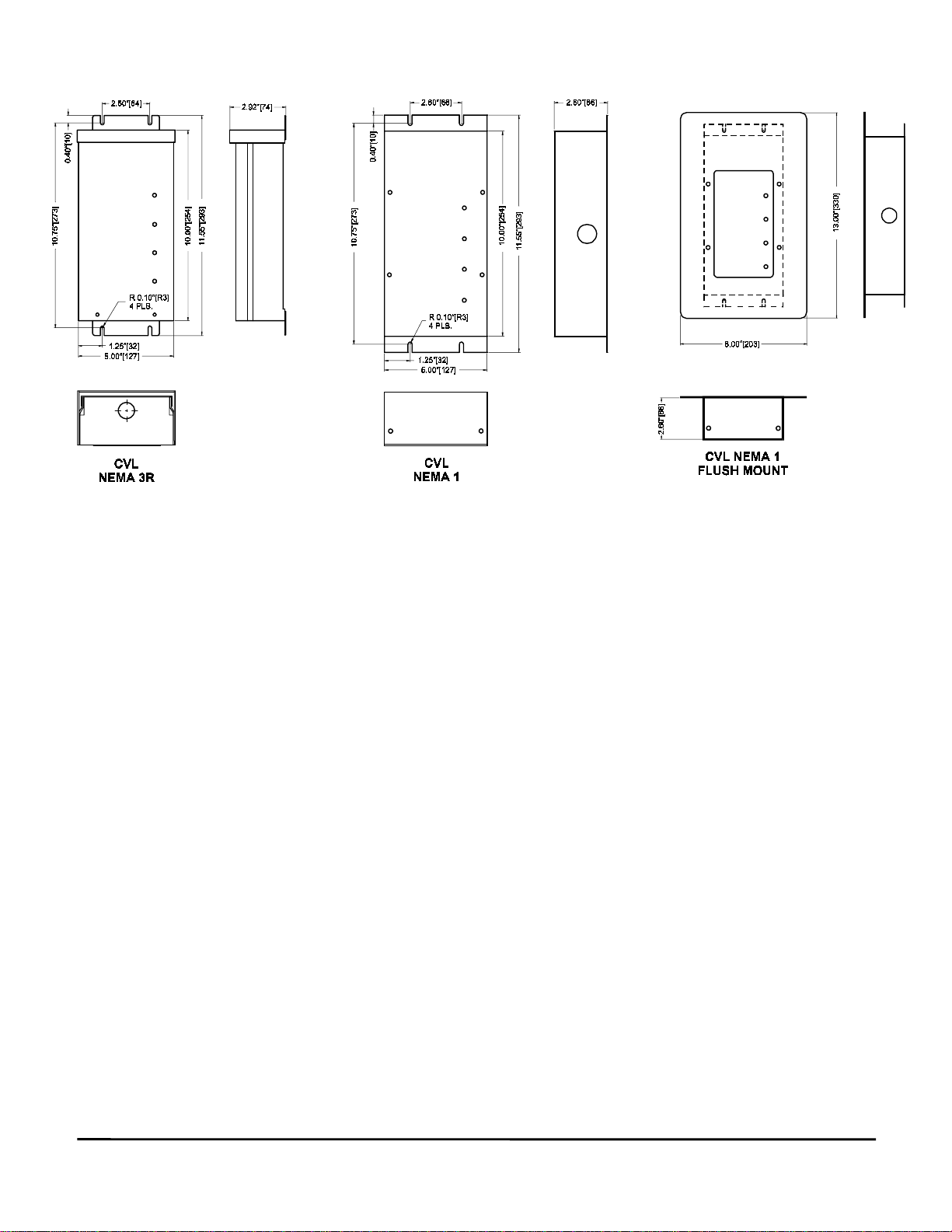
Figure 2: Dimension Details
4.0 Diagnostics and Safety Features
4.1 Status Indicator Lights. To keep you informed of the
SPD’s operating status, each phase is equipped with green
indicator lights. When illuminated, the system is operating
properly. If the lamps are off, a problem may exist within
the SPD.
The Clipper VL is also provided with a green status
indicator lamp, that monitors individual MOVs. If a fault is
found with any MOV, this lamp turns off to indicate a
problem.
The audible alarm and Form C Contacts are tied to the
main status indicator lights and will sound/switch in the
event of a problem.
5.0 Ten Year Warranty
Cutler-Hammer warrants the Clipper VL SPD for a period
of ten years from the date of delivery to the purchaser to be
free from defects in both workmanship and materials.
Cutler-Hammer assumes no risk or liability for results of
the use of the products purchased from it, including but
without limiting the generality of the foregoing: (1) The use
in combination with any electrical or electronic
components, circuits, systems, assemblies or any other
materials or substances. (2) Unsuitability of any product
for use in any circuit or assembly. Purchaser’s rights
under the warranty shall consist solely of requiring Cutler-
Hammer to repair, or at Cutler-Hammer’s sole discretion,
replace, free of charge, F.O.B. factory, any defective items
received at said factory within said term determined by
Cutler-Hammer to be defective. The giving of or failure to
give any advice or recommendations by Cutler-Hammer
shall not constitute any warranty by or impose any liability
upon Cutler-Hammer AND IS IN LIEU OF ANY AND ALL
OTHER WARRANTIES EXPRESSED, IMPLIED OR
STATUTORY AS TO THE MERCHANTABILITY, FITNESS
FOR PURPOSE SOLD, DESCRIPTION, QUALITY,
PRODUCTIVENESS OR ANY OTHER MATTER. In no
event shall Cutler-Hammer be liable for special or
consequential damages or for delay in performance of the
warranty.
This warranty does not apply if the unit has been misused,
abused, altered, tampered with, or applied in excess of the
specifications other than those written on the nameplate.
At the end of the warranty period Cutler-Hammer shall be
under no further warranty obligation expressed or implied.
The Clipper VL SPD covered by this warranty certificate
can only be repaired or replaced by the factory. A
RETURN PRODUCT NUMBER (R.P.N.) must be obtained
and be clearly marked on the outside of the shipping
container as well as on the unit being returned. It should
be forwarded, freight, brokerage and Duty Prepaid to:
Cutler-Hammer, #10, 2256-29th Street N.E., Calgary, AB,
Canada, T1Y 7G4, (403) 717-2000, Fax: (403) 717-0567,
with a detailed description of the fault, your name, address
and telephone number. Repair or replacement will be
returned customer collect. If Cutler-Hammer finds the
return is the result of a manufacturer’s defect, the unit will
be returned prepaid.
6.0 Troubleshooting Guide
The Clipper VL SPD requires no maintenance.
If any green light is off, the unit requires replacement. Call
Cutler-Hammer to arrange delivery for a replacement unit.
U.S.A. 1-800-525-2000
CANADA 1-800-524-5004