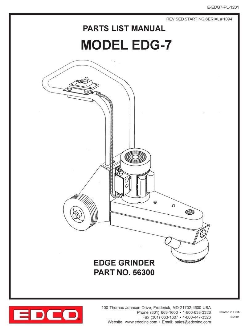
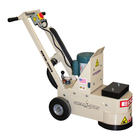
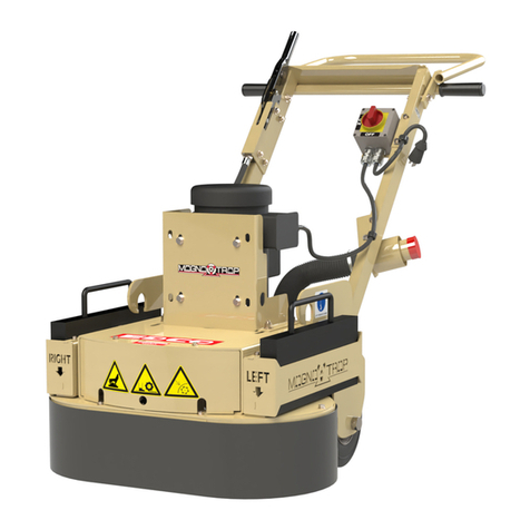
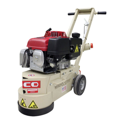
Edco TG-10 Assembly instructions

Printed in USA
TVW ©2003
Page 1
E-TG10-I-0503
100 Thomas Johnson Drive, Frederick, MD 21702-4600 USA
Phone (301) 663-1600 • 1-800-638-3326
Fax (301) 663-1607 • 1-800-447-3326
Operator’s Instruction Manual
TG-10
Turbo Grinder
Available in Gasoline, Propane
and Electric Models

Printed in USA
©2003TVW
Page 2
E-TG10-I-0503
100 Thomas Johnson Drive, Frederick, MD 21702-4600 USA
Phone (301) 663-1600 • 1-800-638-3326
Fax (301) 663-1607 • 1-800-447-3326
READ AND UNDERSTAND THE OPERATORS INSTRUCTION MANUAL THOROUGHLY
BEFORE ATTEMPTING TO OPERATE THIS EQUIPMENT.
Death or serious injury could occur if this machine is used improperly.
Extreme care must be taken when operating electric
models with water present: Ensure power cord is prop-
erly grounded, is attached to a Ground-Fault-Interrupter
(GFI) outlet, and is undamaged.
• Check all electrical cables - be sure connections are tight and
cable is continuous and in good condition. Be sure cable is
correctly rated for both the operating current and voltage of this
equipment.
• Improper connection of the equipment-grounding conductor
can result in a risk of electric shock. Check with qualified electri-
cian or service person if there is any doubt as to whether the
outlet is properly grounded. Adhere to all local codes and ordi-
nances.
•NOTE: In the event of a malfunction or breakdown, grounding
provides a path of least resistance for the electric current to
dissipate. The motor is equipped with a grounded plug and
must be connected to an outlet that is properly installed and
properly grounded. DO NOT modify the plug provided on the
motor. If the plug does not fit the outlet have a qualified electri-
cian install the proper receptacle.
• Switch motor OFF before disconnecting power.
• Engine exhaust from this product contains
chemicals known to the State of California to
cause cancer, birth defects or other reproductive
harm.
• Gasoline is extremely flammable and poisonous. It
should only be dispensed in well ventilated areas,
and with a cool engine.
• Small gasoline engines produce high concentrations of car-
bon monoxide (CO) example: a 5 HP 4 cycle engine operation
in an enclosed 100,000 cu. ft. area with only one change of air
per hour is capable of providing deadly concentrations of CO
in less than fifteen minutes. Five changes of air in the same
area will produce noxious fumes in less than 30 minutes.
Gasoline or propane powered equipment should not be used
in enclosed or partially enclosed areas. Symptoms of CO poi-
soning include, headache, nausea, weakness, dizziness,
visual problems and loss of consciousness. If symptoms oc-
cur - get into fresh air and seek medical attention immediately.
SAFETY
MESSAGES SAFETY MESSAGES
Indicates an imminent hazard which, if not
avoided, will result in death or serious injury.
Indicates an imminent hazard which, if not
avoided, can result in death or serious injury.
Indicates hazards which, if not avoided, could
result in serious injury and or damage to the
equipment.
• Safety Instructions are proceeded by a graphic alert symbol of
DANGER,WARNING,or CAUTION.
ELECTRICAL POWERED EQUIPMENT
GASOLINE/PROPANE POWERED EQUIPMENT
•Equipment should only be operated by trained personnel in
good physical condition and mental health (not fatigued). The
operator and maintenance personnel must be physically able
to handle the bulk weight and power of this equipment.
•This is a one person tool. Maintain a safe operating distance to
other personnel. It is the operators’ responsibility to keep
other people (workers, pedestrians, bystanders, etc.) away
during operation. Block off the work area in all directions with
roping, safety netting, etc. for a safe distance. Failure to do so
may result in others being injured by flying debris or exposing
them to harmful dust and noise.
•This equipment is intended for commercial use only.
•For the operator’s safety and the safety of others, always keep
all guards in place during operation.
•Never let equipment run unattended.
• Personal Protection Equipment and proper safety attire must
be worn when operating this machinery. The operator must
wear approved safety equipment appropriate for the job such
as hard hat and safety shoes when conditions require. Hear-
ing protection MUST be used (operational noise levels of this
equipment may exceed 90db). Eye protection MUST be worn at
all times.
Keep body parts and loose clothing away from moving
parts. Failure to do so could result in dismemberment
or death.
•Do not modify the machine.
• Stop motor/engine when adjusting or servicing this equipment.
Maintain a safe operating distance from flammable
materials. Sparks from the cutting-action of this ma-
chine can ignite flammable materials or vapors.
GENERAL INSTRUCTIONS
DUST WARNING
Some dust created by power sanding, sawing,
grinding, drilling, and other construction activi-
ties contains chemicals known to cause can-
cer, birth defects, or other reproductive harm.
Some examples of these chemicals are:
• Lead from lead-based paints, and
• Crystalline silica from bricks and concrete and other
masonry products.
Your risk of exposure to these chemicals varies depending
on how often you do this type of work. To reduce your risk:
work in a well ventilated area, use a dust control system,
such as an industrial-style vacuum, and wear approved per-
sonal safety equipment, such as a dust/particle respirator
designed to filter out microscopic particles.
• Do not disconnect power by pulling cord. To disconnect, grasp
the plug, not the cord.
• Unplug power cord at the machine when not in use and before
servicing.
Printed in USA
TVW ©2003
Page 3
E-TG10-I-0503
100 Thomas Johnson Drive, Frederick, MD 21702-4600 USA
Phone (301) 663-1600 • 1-800-638-3326
Fax (301) 663-1607 • 1-800-447-3326
EDCO Model TG-10 TURBO GRINDER
Operator’s Instruction Manual
HOW TO ORDER REPAIR PARTS
Toinsureproductsafetyandreliability,alwaysusegenuine
EDCO replacement parts when making repairs to the
equipment.
When ordering parts, please specify the MODEL and
SERIAL NUMBER of the machine as given on the
NAMEPLATE. Inaddition,give part number,description
and quantity as listed on the parts list.
Please note: Due to improvements and changes in the
equipment the illustrations shown may be different from
the actual machine.
TollFree: Voice 1-800-638-3326•Fax 1-800-447-3326
Dimensions and specifications are approximate
and subject to change.
TG10-5B
41”/104cm
24”/61cm
38”/97cm
175 lbs.
Weights include 10” Diamond Disc (20 segments)
TG10-11H
41”/104cm
24”/61cm
38”/97cm
180 lbs.
TG10-11P
41”/104cm
24”/61cm
38”/97cm
220 lbs.
Model
Length
Width
Height
Weight
Table of Contents
Section Page Number
Safety Guidelines....................................................................................................... 4
Operation Instructions.................................................................................................5-8
Maintenance Instructions............................................................................................9-10
Maintenance Schedule.................................................................................................11
Limited Equipment Warranty...................................................................................backcover
Width
Length Height

Printed in USA
©2003TVW
Page 4
E-TG10-I-0503
100 Thomas Johnson Drive, Frederick, MD 21702-4600 USA
Phone (301) 663-1600 • 1-800-638-3326
Fax (301) 663-1607 • 1-800-447-3326
Eye and ear protection must be worn at all times when this machine is in use. During normal use, sound
levelsexceed92dB. UseonlyANSI approvedsafetyglassestohelp prevent eye injury.
Operatormustwearappropriate clothing and footwear. Donotwearlooseclothing or jewelry that can get
tangledinmoving parts.
Grindingcreatesa large volumeofairbornedust. The operator mustwearanapplicable respirator andaheavy
duty vacuum, such as the EDCO VAC-160. The dust may contain chemicals known to cause serious illnesses.
Thevacuumunitshouldbe capable of removingparticlesto 3 micron or less andifnecessary,have the
capability to be equipped with a HEPAfilter. Check the chemical properties of the material to be removed and
followallEPA/OSHAregulations. FAILURE TO COMPLY COULD LEAD TO SERIOUS ILLNESS.
• Keepasafe operatingdistancefrom otherpersonnelandnever leavethemachine running unattended.
• Maintain the machine in safe operating condition with all guards in place and secure, all mechanical fasteners tight,
allcontrolsin working order and thegrinderconfigured for the job application.
• TheTG-10Turbo Grinder isdesignedto remove excess surfacematerial,epoxy or urethanecoatings,forgrinding
highjoints, hard-troweled or polymer concrete, for flattening curling or unevenslabsandforlevelingbridgedecksand
runways.To prevent damagetothe grinder and/or seriouspersonalinjury,avoid protrudingslabinserts,nails,
screws, or any other debris, pipe extensions, uneven joints, machinery bases or any objects that transmit sudden
shock to the grinding assembly.
• TheTG-10Turbo Grinder is tobeoperatedby a properlytrainedandqualified operator from apositionat the rear of
the machine.
• Inspect the disc carefully before installing. Do not use any damaged disc since serious personal injury and/or
damage to the equipment can result.
• Neveroperatethe TG-10 TurboGrinderif under theinfluenceofdrugs, alcohol orwhentaking medications thatimpair
the senses or reactions, or when excessively tired or under stress.
• Be sure all safety decals on the machine can be clearly read and understood. Replace damaged or missing decals
immediately.
Safety Guidelines
Read and understand the Operator’s Manual,
and the Engine Manufacturer’s Owner’s Manual
before operating this equipment.
Death or serious injury can result if this machine is used improperly.
Safetywarningsandguidelinesdonotbythemselveseliminatedanger.
Theyarenotgivenassubstitutesforproperaccidentpreventionandgoodjudgement.

Printed in USA
TVW ©2003
Page 5
E-TG10-I-0503
100 Thomas Johnson Drive, Frederick, MD 21702-4600 USA
Phone (301) 663-1600 • 1-800-638-3326
Fax (301) 663-1607 • 1-800-447-3326
Before Operating:
•Visually inspect machine:
- Verify all guards are in place and fasteners are tight.
-Checkengine oillevel(if gasoline/propane model).
-Inspectpower cord fordamageandcheck for propergrounding(If electric model).
•Inspectdisc assembly:
-Checkdiscsfordamageorwear.
-Check mounting hardware.
- Check belt tension after first 4 hours of use with factory new equipment or after installing new belts.
•Inspect the work area:
Inspect work area carefully before starting to grind. EDCO will not be held responsible for damage to the discs
caused by striking protruding slab inserts, nails, screws, pipe extension, machinery bases, or other objects that
transmit sudden shocks.
Operating Instructions
Exhaust from this engine contains Carbon Monoxide, an invisible,
odorless gas that can kill. In addition, it contains chemicals known, in certain
quantities, to cause cancer, birth defects or other reproductive harm.
Important Reminder!
A water mist system or an industrial vacuum must be used while operating this equipment and the
operator must wear a respirator. Failure to comply could lead to serious illness and possible death.
Figure2
•If dry cutting:
-Hook upheavy-dutyvacuum.
•If wet cutting:
-Attach hose to water supply.
- NOTE: Do not use vacuum when wet cutting.

Printed in USA
©2003TVW
Page 6
E-TG10-I-0503
100 Thomas Johnson Drive, Frederick, MD 21702-4600 USA
Phone (301) 663-1600 • 1-800-638-3326
Fax (301) 663-1607 • 1-800-447-3326
Propane Models: (11 HP Honda Motor with 115V Electric Start)
To Start the Engine:
• Turnonthe main valveatthepropane tank.
• Check all connections for tightness and inspect for leaks. If you detecta gas odor, immediatelyshut off the mainfuel
valveandconsultaqualifiedLP-gasservice person or call EDCO directly.NEVERcheckforleaksusingan open
flame;usealeak-testing solution. NEVER allow propane toescapeinanenclosed area; propane is heavier
than air and will “settle”.
• Tilt the machine back slightly to allow the disc to clear the slab surface.
• Startthe engine according to thedirectionsintheengine manufacturer’s Owner’sManual.
To Stop the Propane Model:
• Tilt the machine back slightly to allow the disc to clear the slab surface.
• Turnthe engineoff.
• Closethevalve onthepropanetank.
Gasoline Models:(11HPHondaEngine)
To Start the Engine:
• Tilt the machine back slightly to allow the disc to clear the slab surface.
• Startthe engine according to thedirectionsintheengine manufacturer’s Owner’sManual.
NOTE: Ifduringoperation refueling becomes necessary, allow the engine tocooldown. NEVERrefuel a hot engine.
To Stop the Gasoline Model:
• Tilt the machine back slightly to allow the disc to clear the slab surface.
• Turnthe engineoff.
Propane is extremely flammable.
To shut off the engine -
PressandholdtheEmergencyStop Button
(Figure 3)
Figure3

Printed in USA
TVW ©2003
Page 7
E-TG10-I-0503
100 Thomas Johnson Drive, Frederick, MD 21702-4600 USA
Phone (301) 663-1600 • 1-800-638-3326
Fax (301) 663-1607 • 1-800-447-3326
Electric Models:
(5 HP Baldor. Available in 1 Phase or 3 Phase)
Dry Grinding:
DryGrindingcreatesa large volume ofairbornedust. Forhealth reasons, the operator shouldwearan
applicable respirator. The dust may contain chemicals known to cause serious illnesses, including Silicosis -
a fatal disease of the lungs. Check the chemical properties of the material to be removed and follow all EPA/
OSHAregulations.
• AnIndustrialvacuum,capableofhandlinghigh volume of fine dust,such astheVAC -
160 (Figure 5), should be used when dry grinding with this machine. If the material
being used is hazardous or contains Silica - the vacuum unit should be capable of
removing Respirable Silica and hazardous particles of less than 3 microns and if
necessary, have the capability to be equipped with a HEPAfilter.
Most standard drum type units use a paper bag filter. The dust created during
grinding is extremely fine and will clog the filter bag of these units and eventually
damagethevacuums motor. Inaddition,damageto theTG-10engine could occur.
• Thecollecteddebrisand filters should be disposed ofaccordingtoproceduresthat
comply with current EPA/OSHAstandards.
Electric units must be connected to a properly grounded
electricalsystemusinganapprovedelectricalcable.
To Start the Machine:
•Tilt the machine back slightly, just enough for the disc to be clear of the slab surface.
•Press the ON button on the power box.
•Gently set the machine back down until the disc touches the slab surface and begin moving the machine.
To Stop the Machine:
•Tilt back the machine to allow the disc to clear the slab surface.
•Press OFF on the power box.
Wet Grinding:
• In the wet grinding stage - water is fed from a standard garden hose into a
ball valve cut off, then into a nozzle that sprays over the disc assembly. (Figure 4)
Use the ball valve to regulate the flow of water to the disc.
Only use enough water flow to reduce dust. Excess water flow will
create clean up problems and could cause a hazardous walking area.
Figure4
Figure5
Vac-160
Always use dust control when using this product.

Printed in USA
©2003TVW
Page 8
E-TG10-I-0503
100 Thomas Johnson Drive, Frederick, MD 21702-4600 USA
Phone (301) 663-1600 • 1-800-638-3326
Fax (301) 663-1607 • 1-800-447-3326
Discs:
• Inspect the disc (Figure 8) periodically to determine it’s wear characteristics, if signs of
unevenwearappear the causeshouldbe determined andcorrected. Ifrepairs are
neededcontactEDCO oryourEDCO representative.
• Each new machine is shipped with a 10”/255 mm factory balanced disk. It is important
to maintain the coupling to which the disk is attached. Aworn coupling, damaged
bearings or a bent shaft will cause the grinding discs to wear unevenly. (Figure 9
shows the head assembly.)
Controlling the Grind:
• Grinding discsare extremely aggressive. It is important to KEEP THE GRINDER MOVING IN A SIDE-TO-SIDE
MOTION, do not let the grinder stay in one spot, even for a few seconds, or the surface will be damaged. When
grinding is completed, tilt the machine back and shut off the power.
• This tool is primarily used to remove excess or damaged concrete surfaces (high joints, slab curling, bridge, road
surface, extra hard surface concrete of 7000 p.s.i. or greater) quickly and at a controlled rate. It is not designed to
produce a smooth, polished finish; it will always leave faint “rings” in the surface. While this is not objectionable for
bridgeworkorother removal work, it will definitelyshowthrougha painted surface or under thinvinyltile.
• To achieve a smooth“polished”surface,completethe grinding operation with anEDCOdualdiscunit using
grinding stones or dyma serts.
• Toremovealight coating, movethegrinder quickly. Forheavierremoval,move the grindermoreslowly.
• Keep the grinding disc flat - do not attempt to grind against vertical surfaces. Be sure the machine is in the correct
operatingposition.(SeeFigures 6 and 7below..)
Figure8
Figure6
CorrectOperatingPosition
Figure7
IncorrectOperatingPosition
(Thisisthetransportmode.)
Figure9
HeadFlange
w/Shaft
P/N86308x
CapScrew
3/8-24x1-3/4
2Required
P/N10029x
3/8LockNut
2Required
P/N10004x
DiamondHead
MountingDisc
1required
P/N86309x
FlatHead
SocketScrew
3/8-24x3/4
4Required
P/N86108x
CapScrew
3/8-24x2
2Required
P/N10030x
DiamondDisc
CustomerOption
Morflex
Coupling
1Required
P/N 86017x

Printed in USA
TVW ©2003
Page 9
E-TG10-I-0503
100 Thomas Johnson Drive, Frederick, MD 21702-4600 USA
Phone (301) 663-1600 • 1-800-638-3326
Fax (301) 663-1607 • 1-800-447-3326
Maintenance
Disconnect spark plug lead (Figure 10) before preform-
inganymaintenanceonthismachine! Oron the electric
model,unplugtheelectriccordatthemachine(instead
ofatthewall)toassurethemachinewillremainun-
plugged while you are working on it.
Every 8 Hours:
• Inspectthediscmountingscrews.(Figure11) The constantvibrationand
heat generated, especially when grinding dry, could cause the screws to
loosen and the disc to become off balance.
Follow the engine manufacturer’s guidelines for regular maintenance.
Every 100 Hours:
• Bearings(Figure12) must belubricatedevery100 hours.
• Belt guard has to be removed to access bearing lubrication
fitting.
Figure10
Figure11
Disc
Mounting
Screws
Figure12

Printed in USA
©2003TVW
Page 10
E-TG10-I-0503
100 Thomas Johnson Drive, Frederick, MD 21702-4600 USA
Phone (301) 663-1600 • 1-800-638-3326
Fax (301) 663-1607 • 1-800-447-3326
Belts:
Toremove/replacebelts:
• Removebeltcover to exposebelts.(Figure13)
• Loosen engine mounting bolts (Figure 14) on both sides of the TG-10 and slide engine to allow belts to slide off.
•Replace worn belts with a complete set of new belts - even if only one belt is showing wear.
• Slide engine back in place until belts are tight and retighten engine mounting bolts.
• Reinstallbeltcover andtightenhardware.
• Afterfourhoursof use, retighten belts.
Figure15
EngineAir Filter:
Inspect the air filters (Figure 15) for excess dust, dirt or
damagebeforethe engine isoperated.More often if
operatingina dustyenvironment.
Operatingtheenginewith a damaged or dirty air filter, or
without an air filter, will allow dirt to enter the engine
causingrapidengine wearwhichwould not be covered
underthe enginemanufacturer’swarranty.
Followthe engine manufacturer’sproceduresfor keeping
the filters in good condition.
Figure14
Figure13

Printed in USA
TVW ©2003
Page 11
E-TG10-I-0503
100 Thomas Johnson Drive, Frederick, MD 21702-4600 USA
Phone (301) 663-1600 • 1-800-638-3326
Fax (301) 663-1607 • 1-800-447-3326
Maintenance Schedule
Read and follow the
engine manufacturer’s
maintenance schedule.
Repairs are to be done by
authorized EDCO Dealers only.
*Whenapplicable.
BeforeOperation
Every4 Hours
Every8 Hours
As Necessary
Adjust Wheel
Height
X
X
X
X
X
X
X
InspectEntire
Machine
* Check Oil & Fuel
Levels
*InspectPropane
Connections
Inspect Disc
InspectBeltTension
LubricateShaft
Bearings
Inspect/Tighten
DiscMountingScrews
* Inspect Vacuum
(empty bins, etc.)
XX
X
X
* CheckAir Filter
(Cleanif Necessary) X

Printed in USA
©2003TVW
Page 12
E-TG10-I-0503
100 Thomas Johnson Drive, Frederick, MD 21702-4600 USA
Phone (301) 663-1600 • 1-800-638-3326
Fax (301) 663-1607 • 1-800-447-3326
USE ONLY GENUINE EDCO PARTS AND ACCESSORIES
For your own safety, the safety of others and the life of your machine
LIMITED EQUIPMENT WARRANTY
Equipment Development Company, Inc. herein
referred to as EDCO warrants that each new unit
manufactured by EDCO to be free from defects in
materia and workmanship in normal use and service
for a period of (1) one year (except in the case of the
cutter drum assembly on all model concrete asphalt
planes, in which case the warranty period shall be 90
days) from date of shipment to the original buyer or
equipment rental center owner.
EDCO will, at its option, repair or replace, at the
EDCO factory or at a point designated by EDCO any
part, which shall appear to the satisfaction of EDCO
inspection to have been defective in material or
workmanship.
Thiswarranty, doesnot applyto failureoccurring asa
result of abuse, misuse, negligent repairs, corrosion,
erosion, normal wear and tear, alterations or
modifications made to the product without express
written consent of EDCO: or failure to follow the
recommended operating practices and maintenance
proceduresas provided inthe productsoperatingand
maintenance manuals.
This warranty does not obligate EDCO to bear any
transportation charges in connection with the
replacement or repair of defective parts. This
warrantydoesnotobligateEDCOtobearanyexpense
for travel time or of personnel in connection with any
service calls.
Accessories or equipment furnished and installed on
the product by EDCO but manufactured by others,
includingbut notlimited toengines, motors, electrical
equipment, transmissions, etc., shall carry the
accessory manufacturers’ own warranty.
THIS WARRANTY IS IN LIEU OF ALL OTHER
WARRANTIES, EXPRESSED OR IMPLIED, OR
STATUTORY, INCLUDING ANY WARRANTIES OF
MERCHANTABILITY OR OF FITNESS FOR A
PARTICULAR PURPOSE.
LIABILITY LIMITATIONS
The remedies of the user set forth under provisions
ofwarranty outlinedabove arethe exclusiveand total
liability of EDCO with the respect to their sale or the
equipment and service furnished hereunder, in
connection with the performance or breach thereof,
or from the sale, delivery, installation, repair or
technical direction covered by or furnished under the
sale, whether based on contract, warranty,
negligence,indemnity, strictliability, orotherwiseshall
notexceedthepurchase price oftheunitof equipment
upon which such liability is based.
EDCO will not in any event be liable to the user, any
successors in interest or any beneficiary or assignee
relating to this sale for any consequential, incidental,
indirect, special or punitive damages arising out of
this sale or any breach thereof, or any defects on, or
failure of, or malfunction of the equipment under this
sale based upon loss of use, lost profits or revenue,
interest, lost goodwill, work stoppage, impairment of
other goods, loss by reason of shutdown or non-
operation, increased expenses of operation of the
equipment, cost of purchase or replacement power
ofclaims ofusers orcustomers ofthe userfor service
interruption whether or not such loss or damage is
based on contract, warranty, negligence, indemnity,
strict liability, or otherwise.
EDCO reserves the right to modify, alter and improve
any part or parts without incurring any obligation to
replaceany partor partspreviously soldwithout such
modified, altered or improved part or parts.
No person is authorized to give any other warranty or
toassumeanyadditional obligationonEDCO’sbehalf
unless made in writing and signed by an officer of
EDCO.
Equipment Development Company, Inc.
Other manuals for TG-10
3
Table of contents
Other Edco Grinder manuals

Edco
Edco Magna-Trap 2D-HDG Assembly instructions

Edco
Edco SECNG-1.5L User manual

Edco
Edco TG-10 Assembly instructions

Edco
Edco TG-10 Assembly instructions

Edco
Edco MAGNA-TRAP TMC-7 Assembly instructions

Edco
Edco MAGNA-TRAP 2EC-NG-1.5 User manual

Edco
Edco MAGNA-TRAP TMC-7 Assembly instructions

Edco
Edco MAGNA-TRAP TMC-7 Assembly instructions

Edco
Edco MAGNA-TRAP TMC-7 Assembly instructions

Edco
Edco 2-EC User manual