manuals.online logo
Brands
  1. Home
  2. •
  3. Brands
  4. •
  5. CYCLEMATIC
  6. •
  7. Lathe
  8. •
  9. CYCLEMATIC CTL-618e User manual

CYCLEMATIC CTL-618e User manual

Popular Lathe manuals by other brands

Jet JWL-1015 operating instructions

Jet

Jet JWL-1015 operating instructions

Holzmann VD 1100ECO user manual

Holzmann

Holzmann VD 1100ECO user manual

Grizzly G0949G owner's manual

Grizzly

Grizzly G0949G owner's manual

Kval 990-H Service manual

Kval

Kval 990-H Service manual

Grizzly G0632 Parts Breakdown

Grizzly

Grizzly G0632 Parts Breakdown

Grizzly G0462 owner's manual

Grizzly

Grizzly G0462 owner's manual

Teknatool Nova Mercury operating manual

Teknatool

Teknatool Nova Mercury operating manual

Milltronics ML Series Instruction handbook

Milltronics

Milltronics ML Series Instruction handbook

Milltronics SL6 Series Instruction handbook

Milltronics

Milltronics SL6 Series Instruction handbook

OmniTurn GT-75 user manual

OmniTurn

OmniTurn GT-75 user manual

Axminster CQ6230A-2/910 user manual

Axminster

Axminster CQ6230A-2/910 user manual

HOLZMANN MASCHINEN ED1000FB user manual

HOLZMANN MASCHINEN

HOLZMANN MASCHINEN ED1000FB user manual

Hercus 260 Maintenance manual

Hercus

Hercus 260 Maintenance manual

Optimum OPTIturn TM 3310 operating manual

Optimum

Optimum OPTIturn TM 3310 operating manual

Grizzly G0709 owner's manual

Grizzly

Grizzly G0709 owner's manual

Traub TNL12.2 operating instructions

Traub

Traub TNL12.2 operating instructions

ELECTRABRAKE EB0625 instruction manual

ELECTRABRAKE

ELECTRABRAKE EB0625 instruction manual

AMMCO 3860 installation instructions

AMMCO

AMMCO 3860 installation instructions

manuals.online logo
manuals.online logoBrands
  • About & Mission
  • Contact us
  • Privacy Policy
  • Terms and Conditions

Copyright 2025 Manuals.Online. All Rights Reserved.

.HOME > PRODUCT > CTL-618e
Special features Specification
Operation manual Optional
This lathe doesn't use threading gearbox, instead
computer-controlled servo motor is directly linked
to the leadscrew. Just use your finger to select
desired thread pitch on the touchscreen display,the
threads come out absolutely precise and you
totally eliminate problems with specialized
threads.The disply also shows spindle speed,
cutting feed rate and DRO functions.
Good for pitch and module turning processing without any gears in gearbox. Easy exchange of inch and
metric system, accuracy goes up to three degits after decirnal point.
Digtal data shows R.P.M. of spindle and tool infeed to let operator arrange best possible turning process
combination.
Digtal data showing electric current for easy checking overload turning.
Rapid retract function is available for shortened pitch module turning processing time.
The lead screw is driven directly by servo- motor. Through operation of interface, a spindle decoder is
used to transfer the motion of lead screw to rectilinear one. The L.C.D touch pad showing the data is
applied to control.
Rapidly returning to the origin is executed according to the principle of temporarily coming off the
tracking mode.
Feeding rate per minute of auto feed is calculated with MODBUS communication protocol interior
message data of the converter, so that user s' cutting precision is available much easily and greatly.
【
Metric / Inch Screen
】【
Digital operation
】
【
Big-character coordinates
】
Click for more detail
If you can't see the detail, Please download Acrobat Reader for PDF file.
CTL-618e toolroom lathe with Digital Threading Control replaces traditional threading gearbox with
microprocessor-controlled, servo-driven leadscrew. In the past, when a machinst is faced with a workpiece
that calls for thread pitch not supported on a conventional lathe, he has to locate and order a custom gear
set and take the time to swap out the gears in the gearbox. This is not economically justifiable unless the
volume is large enough. CTL-618e toolroom lathe's design eliminates this time-consuming workaround.
With the new digital threading system, the user's wishes with it comes to threading can be easily and
immediately realized.
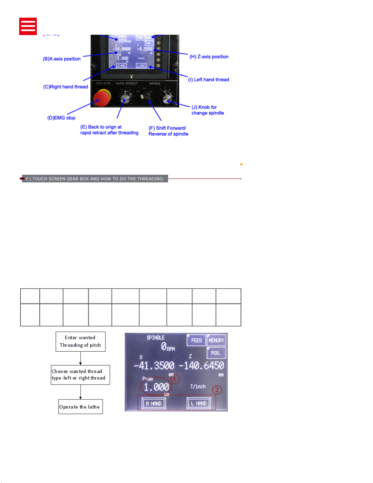
Simply type in the desired thread pitch on the numeric keypad on the touch screen LCD control panel and
then start the threading cycle as on other conventional lathes. CTL-618e's system would control and
synchronize main spindle rotation and Z-axis feed rate to produce precise threading cycle for the given TPI
or mm thread pitch.
Besides being able to cut thread pitches not previously available on manual lathes, noise and vibration
during threading are also significantly reduced, because there are actually no more gears in the gearbox.
Since CTL-618e already has custom IC and a LCD panel to enable threading control, the next logical step
is to integrate DRO functions into it for an all-in-one versatile machine. And CTL-618e has in-fact done
that. DRO capabilities are built-in and come standard with no extra charge. CTL-618e features linear
scales on X and Z-axis from Mitutoyo.
For people experienced with the super high precision and immediacy of CYCLEMATIC's toolroom lathes,
the CTL-618e adds another dimension of capabilities. It builds on the same foundation as 618EVS
toolroom lathe. They are all ideal for super high precision lathe work on small parts (usually those that fit in
5C collets). The guaranteed circular accuracy is 50 millionth of an inch.
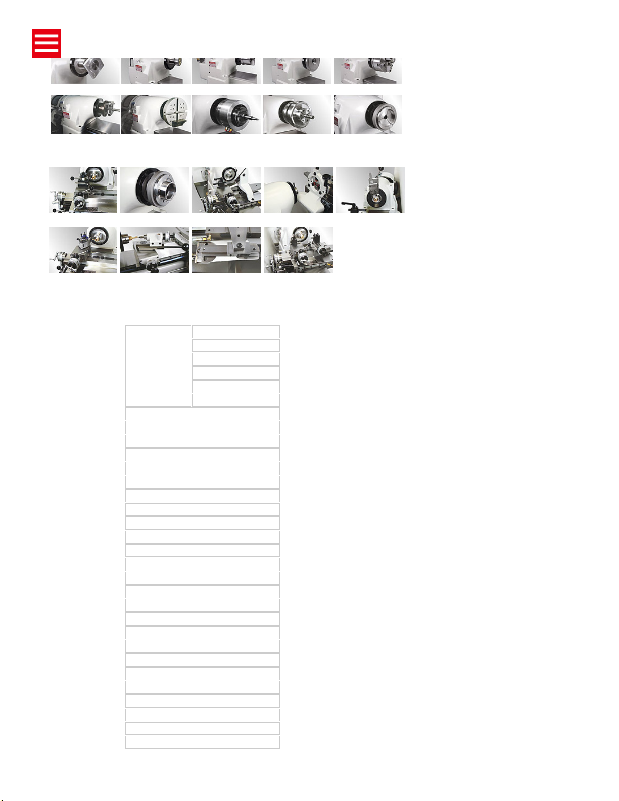
SPINDLE TOOLING, TOOLING HOLDER AND OPTIONAL EQUIPMENT FOR
CYCLEMATIC HIGH SPEED. HIGH ACCURACY TOOLROOM LATHES
MODEL CTL-618e
Spindle Capacity
With Chuck 150 mm (6")
With Expanding Collets 76 mm (3")
With Round 5C Collets 27 mm (1-1/16")
With Hexagon 5C Collets 22 mm (7/8")
With Square 5C Collets 19 mm (3/4")
With Step Chucks 27 ~ 152mm (1-1/16-6")
Spindle Nose Diameter Ø55.5 mm (Ø2.189")
Spindle Nose I.D/O.D 5C (10°) / 4° Tapern
Spindle Speeds (Variable) 50-4,000 rpm (5C) / 50-3,000 rpm ( with 6" 3-jaw chuck)
Inverter Spindle Motor 3 HP
Hole Through Spindle 31.75mm (1-1/4")
Bar stock diameter (5C collet) Ø27 mm (Ø1-1/16")
Distance Between Centers 457 mm (18")
Swing Over Bed 280 mm (11")
Swing Over Carriage 230 mm (9")
Swing Over Cross Slide 152 mm (6")
Carriage Power Feed Range (Variable) 8~178 mm (5/16" ~ 7")
Cross Slide Power Feed Range (Variable) 5~102 mm (3/16" ~ 4")
Cross Slide Travel 152 mm (6")
Quick-action Compound Slide Travel 2.5 mm (0.1")
Compound Slide Travel 76 mm (3")
Tailstock spindle diameter Ø34.5 mm (1.358")
Tailstock spindle taper MT. #2
Tailstock spindle travel 95 mm (3-3/4")
Coolant pump 1/8 HP. 220V. 3PH
Feed Inverter Motor 1/2 HP
Range of Threads 0.55~6.55 mm (3.175~500 TPI)
Main motor 3 HP, 220V, 3PH
feed motor 110V, 70W
Net/Gross weight 2,420/2,640 lb. (1,100 / 1,200 kg.)
Machine packing dimension 2,000 × 850 × 1,900 mm (74" × 34" × 74")
All dimensions, specifications and machine appearance are subject to change without prior notice.
Expanding Collet Vacuum Chuck Hydraulic Chuck Chuck Back Plate 6" 3-jaw Chuck
Lathe Dog Face Plate Pneumatic Chuck Precision Diaphragm
Chucks Step Chuck
Four Station Turret Step Chuck Follow Rest Steady Rest Vertical Cut-off Slide
Quick Change Tool Radius Turning
Attachment
Taper Turning
Attachment
Rear Tool Holder Slide
Assembly
C
T
L
-
6
1
8
e
PURPOSE OF THIS MANUAL
LEVEL ADJUSTMENT PROCESS
LIFTING MACHINE
A.) INSPECTION AND CLEANING OF MACHINE
B.) FOUNDATION, INSTALLATION, AND LEVELING
C.) ELECTRICAL CONNECTIONS
D.) LUBRICATION
E.) SPINDLE CONTROL LEVERS
F.) TOUCH SCREEN GEAR BOX AND HOW TO DOING THE THREADING
G.) MEMORIZE THE X AND Z POSITION
H.) AUTOMATIC THREAD LENGTH CONTROL
I.) SPINDLE BRAKE
J.) BELT ADJUSTMENT
K.) COLLET CLOSER-REMOVAL
LM.) COLLET CLOSER-REPLACEMENT
M.) COLLET CLOSER-ADJUSTMENT
N.) CARRIAGE INDICATED RING
O.) CARRIAGE LOCK
P.) CARRIAGE CLUTCHES
Q.) CROSS SLIDE INDICATING RING
R.) QUICK-ACTING TOOL POST COMPOUND SLIDE ASSEMBLY
S.) POWER FEED UNIT
T.) COOLANT FACILITIES
U.) TAILSTOCK
V.) TAILSTOCK SPINDLE LOCK
W.) TAILSTOCK BODY LOCK
OPERATION
The model CTL-618e series machine is built for easy and safe operation and excellent manufacturing of
work in process. The machine is built with high quality material, and carefully to exacting standards that
guarantee the life, economical use, accuracy, and minimum maintenance of the machine.
This manual is an introduction to the CYCLEMATIC model CTL-618e HIGH ACCURACY TOOL ROOM
LATHE. It is used for installation, operation and servicing of the CTL-618e CYCLEMATIC MACHINES.
Also, for fast reference, because it is necessary to make minor adjustments or do preventive maintenance.
(For personnel and operators who deal with the CTL-618e machine.)
FOR MODEL CTL-618e EQUIPPED WITH ELECTRONIC VARI-SPEED SYSTEM
TOP
Place Two Levels on Slide Way
CTL-618e
TOP
1. Put pads C (Figure B) under each of six points.
2. Loose set screw A (Figure B)
3. Insert a pin wrench into the hole B. raise or lower by turning (C.C.W.or .C.W)
4. Tighten set screw A (Figure B) to lock.
5. Be sure every point is touching the ground to support the machine.
Figure 1 - Lifting machine
Lifting machine, arrange rope or cable as shown in figure 1, and check to see if the correct balance has been
obtained. Then insert pads of soft cloth between the edges of the rope and machine. The net weight of this
machine is approx 1100 kgs (2420 lbs). So the rope or cable must be rated at 3000 lbs capacity.
TOP
An inspection should be made after arrival of the machine in your plant. Look for possible damage caused by
shock or vibration during transportation, also check for any missing parts, standard tools or other equipment.
In shipment, all exposed surfaces of the machine are coated with a antirust liquid. Before moving carriage
and cross-slide, lead screw, tailstock…etc, these surfaces should be thoroughly cleaned to remove all
antirust liquid use a soft brush and solvent. This is very important because it can prevent any dirt or grit which
may have accumulated on the antirust liquid from working under the sliding members and causing undue
wear.
※CAUTION:
DO NOT USE COMPRESSED AIR TO CLEAN, WHICH WILL REDUCE THE MACHINES LIFE
TOP
A fairly flat foundation and proper installation will provide the machine long-term high accuracy, so
supplying a good solid foundation of proper thickness is important. (Generally, a thickness of 300mm (12")
is considered to be enough.) The machine has six adjustable feet on the corners of the pedestal base, used
for leveling the machine. Place the pads under the feet of pedestal. To adjust, loosen the set screw and
raise or lower the foot with a pin wrench so that all six feet rest firmly on the floor. When the adjustment is
done, tighten set screws.
TOP
The CTL-618e TOOLROOM LATHE is shipped completely wired and
assembled, Turn Cam Switch "A" (Figure 2) to the "OFF" position, then check
motor voltage. Loosen screws "B" (Figure 2), and open the switch case cover,
connect the wires from the power source to the terminals (R.S.T), and ground
connection is made at the "G" (Figure 3) which is the electric switch case.
Pull out Spindle locking Pin "E" (Figure 4), push "G" (Figure 4) in forward
position. The spindle should rotate counterclockwise when viewed from the
tailstock end of the machine. If the spindle does not turn in the correct direction,
turn Cam Switch "A" (Figure 2) to "OFF" position. Disconnect electric power
source, and interchanges any two leads until the turning direction is correct.
When the spindle is rotation correctly, secure switch case cover, turn Cam
Switch "A" (Figure 2) to "ON" position.
Figure 2-Control Unit Door
Figure 3-Control Unit
Figure 4-Control Speed and Direction
TOP
Proper lubrication supplied carefully , will maintain the life and performance of the machine for a long period.
Therefore, lubricate the machine with a high quality lubricant, and check periodically to assure that the
lubricant in the oil sight gage is filled to the proper level.
1. CARRIAGE LUBRICATION
Fill with Mobil Vactra Oil No.2 or equivalent in oil reservoir. Lift plunger on reservoir "R" (Figure 5) hold briefly
and release to keep bed ways lubricated.
Figure 5-Speed Change Unit
2. GEAR BOX AND CLUTCH LUBRICATION
Maintain oil level in sight windows "W" (Figure 7). To fill gearbox, remove plug "C"(Figure 7) use Automatic
Transmission Fluid Mobil 200 (Esso ATF or equivalent Change oil every 500 hours).
To drain oil, remove the Drain Plug "M" located under the oil gear box (Figure 7).
Figure 7-Gear Box Lubrication
※CAUTION:
USE OF ANY OTHER TYPE OF OIL IN THE GEARBOX MAY RESULT IN DAMAGE TO THE CLUTCH
SURFACES.
3. HEADSTOCK LUBRICATION
The headstock spindle is mounted on precision preloaded ball bearings. The ball bearings are grease packed
for life and require no further lubrication.
TOP
To change spindle speeds. Push start button "D" (Figure 8). Turn cam switch "C" (Figure 10) to the forward or
reverse position and move lever "G" (Figure 9) to the start position. Turn cam switch "D" (Figure 10) right to
increase speed or turn left to decrease speed.
Figure 8-Control Unit Door Figure 9-Control Speed and Direction
Figure 10-Control Speed Control Box
TOP
While you threading, you have to following the steps to set up, first choose the mm/inch set the pitch size by
touch screen, and choose the Right hand threador Left hand thread "F" by touch screen, after that choose the
pitch "G" (Figure 12) and engage the lead screw nut "J" (Figure 13) by moving ball handled lever "I" (Figure
13) clockwise. Start the spindle by moving the lever "G" (Figure 12). Move the lever "D" (Figure 12 )to make
movement going left or right. The threading speed is control by server motor , so if your let the spindle speed
faster, the threading speed also will going faster, The rapid speed is control by rapid retract cam "E"
(Figure10 ).
※CAUTION:
THIS TOUCH SCREEN CAN DOING THE THREADING PITCH
0.01~6.35mm/4~99TPI. (The following speed depends on material)
FOLLOW SPINDLE SPEED LIMIT FOR THREADING OPERATION:
Pitch 0.05 ~
1.0mm
1.001 ~
2.0mm
2.01 ~
4.0mm
4.001 ~
6.55mm
25.001 ~
550Tpi
12.001 ~
25Tpi
6.501 ~
12Tpi
3.175 ~
6.5Tpi
Spindle
R.P.M
Limit
3200 1600 800 400 3200 1600 800 400
Figure 11-Control Speed Control Box
Figure 12-Feed of Thread Change Figure 13-Carriage Clutches
※CAUTION:
PLEASE FOLLOW TOP OF THREAD CHART , THE SPINDLE SPEED DO NOT OVER SPEED . IF
SPINDLE SPEED OVER THE LIMIT , THE TOUCH SCREEN WILL APPEAR "SPINDLE OVER" . ALSO THE
THERADING FUNCTION WILL NOT WORK .
TOP
Touch the memory bottom will apper the digital operation system. Touch the SET button before doing any
memorize step. If didn't touch set button and memorize key can not be work. Touch the memorize Z and X
position. For digital operation have 8 set of memory to memorize the X and Z position. Touch the "switch
to 1~4 memory set or 5~8 memory . Touch RETURN to return to the main screen.
Figure 14-Control Speed Control Box
TOP
Figure 15- Speed Control Box
Figure 16- Speed Control Box
TOP
Figure 17- Speed Control Box
TOP
When threading into a blind hole or to a shoulder without a thread relief. The lead screw half nut if engaged at
the start of the threading work is completed. Left or right hand threads are controlled by Control lever "D"
(Figure 18), the lever is joined with the control bar "B" (Figure 19). When the carriage touches the adjusting
screw "S" (Figure 19) of the length control bar, it will push the lever "D" (Figure 18) to "STOP" position, and
make the lead screw stop.
Figure 18-Control Speed and Direction
Figure 19-Thread Length Control
TOP
Inverter unit "D" is used to perform dynamic braking. In addition,
discharge resister "C" shortens braking time (Figure 20).
Figure 20-Control Unit
TOP