ViM UTBS ECOWATT PRO-REG User manual

NT00000850-UTBS-ECOWATT-PRO-REG-ETD2-AN-230623
INSTRUCTION MANUAL
INSTALLATION | WIRING | COMMISSIONING | MAINTENANCE |
AFNOR CERTIFICATION
ISO 14001
Environnement
AFNOR CERTIFICATION
ISO 9001
Qualité
UTBS ECOWATT®PRO-REG
CORRIGO ETD2 regulation
Regulated single ow air handling unit (AHU)
Compact unit for false ceiling

2/64 NT00000850-UTBS-ECOWATT-PRO-REG-ETD2-AN-230623
SOMMAIRE
1. GENERAL........................................................................................................................................... 4
1.1 Warnings .................................................................................................................................. 4
1.2 Safety instructions .................................................................................................................... 4
1.3 Reception – Storage................................................................................................................. 5
1.4 Warranty ................................................................................................................................... 5
2. PRODUCT RANGE PRESENTATION................................................................................................ 5
2.1 Range....................................................................................................................................... 5
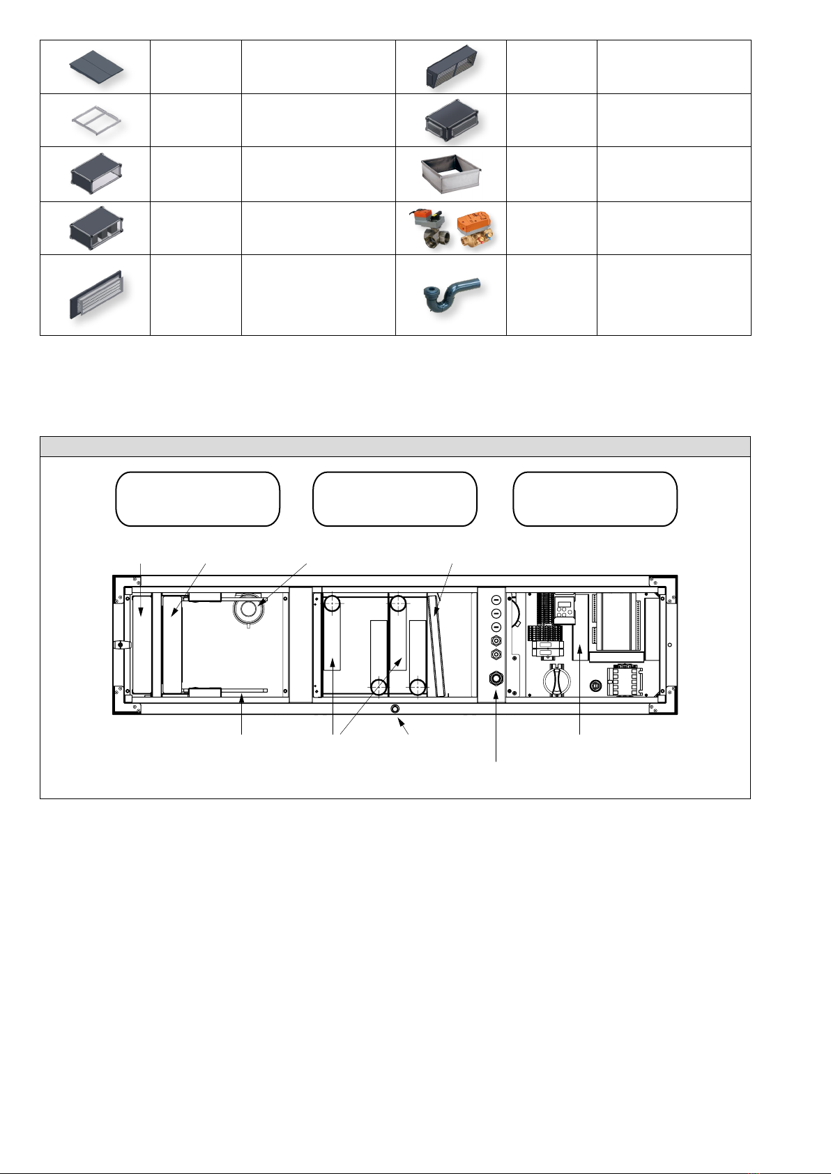
2.2 Main components ..................................................................................................................... 7
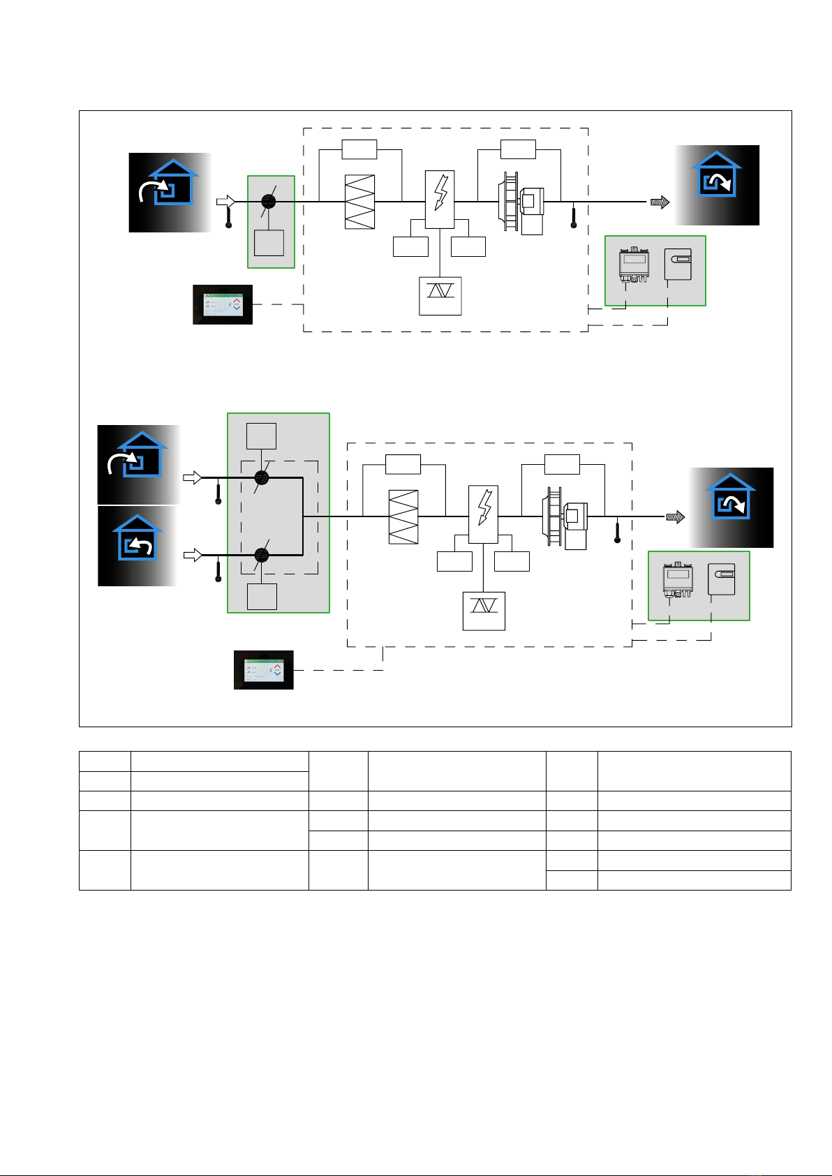
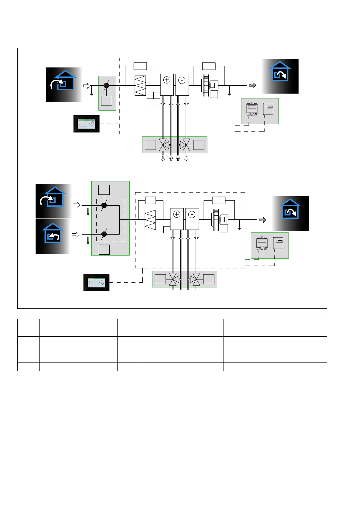
2.3 Functional synoptics (examples) .............................................................................................. 8
3. INSTALLATION ................................................................................................................................ 12
3.1 Machine identication............................................................................................................. 12
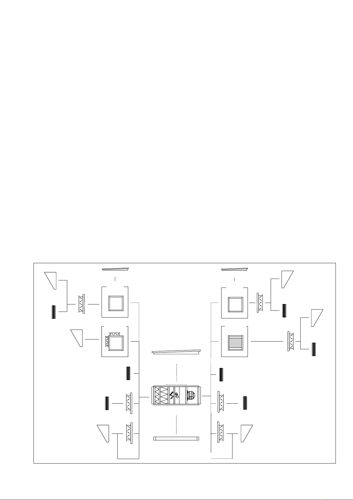
3.2 Dimensions and weights......................................................................................................... 12
3.3 Handling and lifting................................................................................................................. 18
3.4 Location and mounting ........................................................................................................... 18
3.5 Fitting accessories.................................................................................................................. 20
4. HYDRAULIC AND FLUID CONNECTION ....................................................................................... 22
4.1 Connecting the water coils ..................................................................................................... 22
4.2 Connection of hydraulic accessories...................................................................................... 23
4.3 Connection of direct expansion coils (DX).............................................................................. 24
4.4 Condensate drain ................................................................................................................... 25
4.5 Temperature sensors.............................................................................................................. 25
5. AIR DUCT CONNECTION................................................................................................................ 26
5.1 Duct connection...................................................................................................................... 26
5.2 Accessories connection.......................................................................................................... 27
6. ELECTRICAL CONNECTIONS AND FEATURES ........................................................................... 27
6.1 Electrical connections............................................................................................................. 27
6.2 Electrical features................................................................................................................... 27
6.3 CORRlGO controller - Technical datas................................................................................... 28
6.4 Remote control with ETD2 display - Connection.................................................................... 28
6.5 Internal electrical board - Description and connection............................................................ 30
6.6 External components connection diagrams (examples)......................................................... 32
6.7 Connecting accessories for temperature control with internal coil ......................................... 34
7. CONTROL - FUNCTIONAL ANALYSIS ........................................................................................... 35
7.1 Main elements of control ........................................................................................................ 35
7.2 Airow control fan................................................................................................................... 36
7.3 Temperature control................................................................................................................ 37
7.4 Special case: temperature control with EX direct expansion coil ........................................... 38
7.5 Heating water coil frost protection (EC / ECF / ER versions) ................................................. 39
7.6 AHU start and stop sequences............................................................................................... 39
7.7 Input for external re signal .................................................................................................... 40
7.8 Clock and time programming.................................................................................................. 40
8. USE OF REMOTE CONTROL ETD2 ............................................................................................... 41
8.1 Presentation of the ETD2 remote control ............................................................................... 41
8.2 Stop the air handling unit........................................................................................................ 42
8.3 Main settings .......................................................................................................................... 42
8.4 Specic settings for ventilation modes CAV/VAV/COP........................................................... 45
8.5 Time schedule ........................................................................................................................ 49
8.6 Setting the communication protocol ....................................................................................... 51
8.7 Save and restore .................................................................................................................... 52
8.8 Expert level settings ............................................................................................................... 53
9. BMS COMMUNICATION .................................................................................................................. 53
9.1 Communication in Modbus protocol ....................................................................................... 53
9.2 Communication in BACnet protocol........................................................................................ 56
10. COMMISSIONING ............................................................................................................................ 56
10.1 AHU factory settings............................................................................................................... 56
10.2 Factory control of air handling units........................................................................................ 57
10.3 Recommendations.................................................................................................................. 57

3/64 NT00000850-UTBS-ECOWATT-PRO-REG-ETD2-AN-230623
11. MAINTENANCE - REPLACEMENT OF PARTS - ALARMS............................................................ 57
11.1 Safety instructions .................................................................................................................. 57
11.2 Maintenance frequency .......................................................................................................... 58
11.3 Maintenance / replacement of fresh air lters......................................................................... 59
11.4 Maintenance / resetting / replacing the electric heater........................................................... 60
11.5 Maintenance / replacement of the water coil.......................................................................... 60
11.6 CORRIGO controller - Reset and battery replacement .......................................................... 61
11.7 Alarms and faults.................................................................................................................... 63
11.8 List of main spare parts .......................................................................................................... 64
12. WASTE MANAGEMENT .................................................................................................................. 64
12.1 Treatment of Packaging and non-hazardous waste ............................................................... 64
12.2 Treatment of Professional WEEE........................................................................................... 64

4/64 NT00000850-UTBS-ECOWATT-PRO-REG-ETD2-AN-230623
1. GENERAL
1.1 Warnings
This product has been manufactured in compliance with rigorous technical safety rules, according to CE
standards. The CE declaration and the manual can be downloaded from the website www.vim.fr.
Before installing and using this product, carefully read these instructions which contain important infor-
mation for your safety and that of users during the installation, commissioning and maintenance of this
product.
Once installation is complete, leave this manual in the machine for future reference.
The installation of this product (implementation, connections, commissioning, maintenance) and all other
interventions must be carried out by a professional applying the rules of the art, the standards and the
safety regulations in force.
It must comply with the requirements relating to Electro Magnetic Compatibility and the Low Voltage Di-
rective.
The manufacturer cannot be held liable for any injury and/or material damage caused when the safety
instructions have not been respected or following a modication of the product.
UTBS ECOWATT
®
PRO-REG single-ow units are intended for single-ow ventilation and air treatment
applications in kitchens or tertiary buildings.
Indoor (recommended) or outdoor installation:
• Maximum permanent environment temperature: -20°C / +40°C.
• To avoid any damage to the electronic components (very low temperature, condensation) the safety
switch located on the front panel must be kept in the “ON” position, except during maintenance pe-
riods.
• Relative humidity: max. 95% without condensation.
• Non-potentially explosive atmosphere.
• Low salinity atmosphere, free from corrosive chemical agents.
1.2 Safety instructions
General
• Meaning of the danger labels present on the access doors:
Live equipment Rotating machine Potentially ammable dusty f ilters
• Put on appropriate PPE (Personal Protective Equipment) before any intervention.
• Before installing the air handling unit, ensure that the support and location are strong enough to
• support the weight of the unit and accessories.
• Do not open doors or panels without shutting down the unit.
Case of emergency or danger
• Switch o the power supply using the lockable disconnect switch and, if possible, the main circuit
breaker.

5/64 NT00000850-UTBS-ECOWATT-PRO-REG-ETD2-AN-230623
AHU normal shutdown procedure
• Stop the unit from the ETD2 remote control or the BMS to allow ventilation of the electric heater, if pre-
sent, before stopping the fans and the AHU. See § "8.2 Stop the air handling unit", page 42.
• Switch o the power supply using the lockable disconnect switch and, if possible, the main circuit
breaker.
• Make sure that moving parts are stationary.
Before starting, check the following points:
• Check the earth connection.
• Check that the access doors are properly closed.
Tripping of safety thermostats (EI model)
• UTBS ECOWATT® are equipped with 2 safety switch thermostats:
-A manual reset thermostat switches off the heater at 85°C.
-An automatic reset thermostat switches off the heater at 60°C.
• Any resetting or tripping information (via the BMS for example) involves looking for the cause of this
triggering on the AHU and on the installation. Contact [email protected].
1.3 Reception – Storage
In the event of lack, non-compliance, total or partial damage to the products delivered, the buyer must, in
accordance with article 133-3 of the Commercial Code, issue written reservations on the carrier's receipt
and conrm them 72 hours by sending a registered letter to the transporter and a copy to the manufacturer.
The receipt without reservation of the equipment deprives the Buyer of any further recourse against us.
The product must be stored away from bad weather, shocks and dirt due to projections of any kind during its
transport from the supplier to the end customer, and on the site before installation.
1.4 Warranty
The equipment is guaranteed for 24 months from the invoice date. The warranty is limited to the replace-
ment of parts or equipment whose operation is recognized as defective by the manufacturer, excluding
any compensation or penalties. The costs of labor, removal and rest, travel related to the replacement are
the responsibility of the Customer. Excluded from our warranty are linked to abnormal use or not in accor-
dance with the recommendations in our instructions, defects observed as a result of normal wear and tear,
incidents caused by negligence, lack of monitoring or maintenance, defects due to incorrect installation of
devices or poor storage conditions prior to assembly.
In any case, manufacturer is not responsible for transformed material, even partially repaired.
2. PRODUCT RANGE PRESENTATION
2.1 Range
Usage:
• Introduction of fresh air, heating and air conditioning.
• Indoor or outdoor installation.
• Floor or ceiling mounting, or vertical see § "3.4 Location and mounting", page 18.
4 sizes:
UTBS ECOWATT® 2 (2 000 m3/h), UTBS ECOWATT® 3 (3 000 m3/h), UTBS ECOWATT® 5 (5 000 m3/h),
UTBS ECOWATT® 8 (8 000 m3/h),

6/64 NT00000850-UTBS-ECOWATT-PRO-REG-ETD2-AN-230623
Congurations according to the types of built-in coils or heater:
• UTBS ECOWATT®EI : integrated electric heater.
• UTBS ECOWATT®EC : integrated hot water coil.
• UTBS ECOWATT®ER : integrated reversible water coil.
• UTBS ECOWATT®ECF : integrated hot water coil + cold water coil.
• UTBS ECOWATT®EIF : integrated electric heater + cold water coil.
• UTBS ECOWATT®EX : integrated direct expansion coil.
Upward vertical air ow mounting possible for versions with hot water coil or electric heater.
4 constructions - rectangular line connection:
• UTBS ECOWATT®D : indoor installation - Right hand side access
• UTBS ECOWATT®G : indoor installation - Left hand side access
• UTBS ECOWATT®EXD : outdoor installation with roof mounted - Right hand side access
• UTBS ECOWATT®EXG : outdoor installation with mounted roof - Left hand side access
Self-supporting structure in 25 mm double skin panels.
• Insulation by mineral rock wool th. 25 mm, density 40 kg/m3.
• Thermal conductivity 0,037 W/(m.k) (20/80°C).
A1 re classication according to standard EN 13 501.1.
Interior nishing in Z275 galvanized steel and exterior nishing in pre-painted steel, C5 corrosion resistant.
Access from the side and/or bottom panels.
Possibility of adding a base frame (accessory).
Modbus communicating control mounted / cabled – ready to be connected:
• Variable airow (VAV), constant airow (CAV), constant pressure (COP).
• Temperature control by the VIM specic integrated CORRIGO programmable logic controller.
• Modbus communicating - ready to be connected control on port RS485 and BACnet IP on port TCP/IP.
• Remote touch panel (ETD2) control included.
• ASR ECOWATT
®
system for association with an ASR ECOWATT® exhaust fan for kitchen ventilation
- See "NT00000579-SYSTEME-ASR-ECOWATT" manual available at www. vim.fr.
Accessories
VF
UTBS
Caisson de
Mélange
IDJF
ID
JF
VF
ID JF
ID
JF
VF ou VL
Caisson
Silencieux
Caisson
Plénum
TPP
Châssis
Caisson
Plénum
ID
JF
VF ou VL
TPP TPP
ID JF
VF ou VL
ID JF
VF ou VL
VF or VL VF or VL
VF or VL
VF or VL
Base frame
Plenum
module
Plenum
module
Silencer
module
Mixing
module

7/64 NT00000850-UTBS-ECOWATT-PRO-REG-ETD2-AN-230623
TPP Roof VF / VL Front and side rain
protection
BBase frame CM 2-way mixing module
PB Plenum module
JF Flexible rectangular
connection M0.
SIL Silencer module
VTVS
VDVP
2-way or 3-way constant
pressure valves
ID + actuator
(accessory)
Motorizable rectangular
damper. Air inlet
mounting to ensure frost
protection coil, or air
outlet mounting
SIPH Standard siphon to
prevent pipe odors.
Accessories dimensions on page 15.
2.2 Main components
ECF models
SECTION
FILTRES
SECTION
BATTERIES
SECTION
VENTILATEURS
Raccord d’entrée de câblage
Sortie condensatsBatteries
Séparateur de gouttelettes
Pré-ltre Filtre nal
Panneau de commandeSystème de serrage de ltres
Détecteur d’encrassement des ltres
FILTERS
SECTION
COIL
SECTION
FANS
SECTION
Pre-lter
Filter clamping system Coils Condensate drain
Wiring entry
Control panel
Final lter Filter pressure switch Droplet separator

8/64 NT00000850-UTBS-ECOWATT-PRO-REG-ETD2-AN-230623
2.3 Functional synoptics (examples)
Conguration with electric heater (EI / EIF)
Prise air neuf
extérieur
Prise air neuf
extérieur
Souage air neuf
intérieur
Souage air neuf
intérieur
Reprise air vicié
intérieur
Accessoire
S2/S3 M4
ID
ETD2
F
DP1
Pr1Pr2
Triac
E
M1
DP3
S1
SPRD SCO2
Accessoire
Accessoire
S2
M4
M4 CM
ETD2
F
DP1
Pr1Pr2
Triac
E
M1
DP3
S1
SPRD SCO2
Accessoire
S3
Outdoor
fresh air
Outdoor
fresh air
Supply air
Supply air
Accessory
Accessory
Accessory
Accessory
Indoor
air return
M1 Supply air fan S3 Indoor air temperature
sensor Pr1/
Pr2
Safety thermostat switch
(manual/auto)
Triac Electric heater controller
EElectric heater DP1 Filter pressure switch ID Fresh air damper (accessory)
S1 Supply air temperature
sensor
DP3 Airow measurement CM Mixing module (accessory)
ETD2 Remote control M4 Damper actuator (accessory)
S2 Outdoor air temperature
sensor FFilter SCO2 Air quality sensor (accessory)
SPRD Pressure sensor (accessory)

9/64 NT00000850-UTBS-ECOWATT-PRO-REG-ETD2-AN-230623
Conguration with hot and/or cold water coils (EC / EIF / ECF)
Accessoire
S2/S3 M4
ID
ETD2
ETD2
Ventilateur souage
F
DP1
PrF
M7
M6
Bat 1
M1
DP3
S1
SPRD SCO2
Accessoire
Accessoire
Bat 2
Accessoire
S2
M4
M4 CM
F
DP1
PrF
Bat 2
M7M6
M1
DP3
S1
SPRD SCO2
Accessoire
S3
Bat 1 Accessoire
Prise air neuf
extérieur
Souage air neuf
intérieur
Souage air neuf
intérieur
Prise air neuf
extérieur
Reprise air vicié
intérieur
Outdoor
fresh air
Outdoor
fresh air
Supply air
Indoor
air return
Accessory
Accessory
Accessory
Accessory
Accessory
Accessory
Supply air
M1 Supply air fan ETD2 Remote control PrF Antifrost sensor
DP1 Filter pressure switch FFilter ID Fresh air damper (accessory)
S1 Supply air temperature sensor Bat 1 Hot water coil CM Mixing module (accessory)
S2 Outdoor temperature sensor Bat 2 Cold water coil M4 Damper actuator (accessory)
S3 Indoor temperature sensor M6 Valve actuator (hot) SCO2 Air quality sensor (accessory)
DP3 Airow measurement M7 Valve actuator (cold) SPRD Pressure sensor (accessory)

10/64 NT00000850-UTBS-ECOWATT-PRO-REG-ETD2-AN-230623
Conguration with reversible water coil (ER)
Accessoire
M6
Bat 1
S20
PrF
Accessoire
M6
Bat 1
S20
PrF
Accessoire
Accessoire
Accessoire
SPRD SCO2
Accessoire
M4
M4
M4
ETD2
CM
F
DP1
M1
DP3
S1
S2
S3
ID
DP1
FM1
DP3
S1
SPRD SCO2
ETD2
S2/S3
Prise air neuf
extérieur
Prise air neuf
extérieur
Souage air neuf
intérieur
Souage air neuf
intérieur
Reprise air vicié
intérieur
Outdoor
fresh air
Outdoor
fresh air
Indoor
air return
Accessory
Accessory
Accessory
Accessory
Accessory
Accessory Supply air
Supply air
M1 Supply air fan ETD2 Remote control S20 Change-over thermostat THCO
S1 Supply air temperature
sensor
DP1 Filter pressure switch ID Fresh air damper (accessory)
PrF Antifrost sensor CM Mixing module (accessory)
S2 Outdoor temperature sensor FFilter M4 Damper actuator (accessory)
S3 Indoor temperature sensor Bat1 Water coil (reversible) SCO2 Air quality sensor (accessory)
DP3 Airow measurement M6 Valve actuator (heating/cold) SPRD Pressure sensor (accessory)

11/64 NT00000850-UTBS-ECOWATT-PRO-REG-ETD2-AN-230623
Conguration with direct expansion coil (EX)
Accessoire
Accessoire
Accessoire
SPRD SCO2
Accessoire
M4
M4
M4
ETD2
CM
F
DP1
M1
DP3
S1
S2
S3
ID
DP1
F
DX
Kit DX Groupe
DX
M1
DP3
S1
SPRD SCO2
ETD2
S2/S3
DX
Kit DX Groupe
DX
Prise air neuf
extérieur
Prise air neuf
extérieur
Souage air neuf
intérieur
Souage air neuf
intérieur
Reprise air vicié
intérieur
Outdoor
fresh air
Outdoor
fresh air
Indoor
air return
Supply air
Supply air
Accessory
Accessory
Accessory
Accessory
DX kit
DX kit
DX
unit
DX
unit
M1 Supply air fan DP1 Filter pressure switch ID Fresh air damper (accessory)
S1 Supply air temperature sensor FFilter CM Mixing module (accessory)
S2 Outdoor temperature sensor DX Direct expansion coil M4 Damper actuator (accessory)
S3 Indoor temperature sensor DX unit Direct expansion unit SCO2 Air quality sensor (accessory)
DP3 Airow measurement Kit DX Control box provided by the
supplier of the DX unit SPRD Pressure sensor (accessory)
ETD2 Remote control

12/64 NT00000850-UTBS-ECOWATT-PRO-REG-ETD2-AN-230623
3. INSTALLATION
3.1 Machine identication
Identication label stuck on the panel of the fan box.
3.2 Dimensions and weights
Conguration 3 Conguration 4 Conguration 5 Conguration 6
EC2 ou EC4FM5
or
ER4 ou ER6
EX4 ou EX6 M5F
or
or
EF4 ou EF6 EC2 M5F
or
EI M5FEF4 ou EF6
or
Conguration 7
FM5EI
EC2 2 rows heating coil EX6 6 rows direct expansion coil
EC4 4 rows heating coil EI Electrical heater
EF4/ER4 4 rows cooling coil / or reversible M5 FIFI M5 ePM10 lter 50%
EF6/ER6 6 rows cooling coil / or reversible FFIFI F7 or FIFI F9 lter location
EX4 4 rows direct expansion coil

13/64 NT00000850-UTBS-ECOWATT-PRO-REG-ETD2-AN-230623
Conguration 3
B
1454
A
C
E
1394
D
J
80586
Conguration 4
3/4"
B
1454
A
C
E
1394
D
587 K
J
722,5
Dimensions (mm) and Weight (Kg) Cong. 3 Cong. 4
Size A B C D E J
K
2-4 rows /
6 rows
Connection
(")
water coil
Weight
2 rows /
4 rows
Weight
4 rows /
6 rows
2750 360 690 300 790 215 80 / 120 1-1/4" 112 / 115 120 / 122
31 100 410 1 040 350 1 140 265 80 / 120 1-1/4" 158 / 168 174 / 179
51 500 410 1 440 350 1 540 265 80 / 120 1-1/4" 208 / 224 228 / 236
81 900 500 1 840 440 1 940 330 80 / 120 1-1/2" 258 / 270 283 / 293

14/64 NT00000850-UTBS-ECOWATT-PRO-REG-ETD2-AN-230623
Conguration 5
3/4"
B
1454
A
C
E
1394
D
586 80
J
K
723,5
Conguration 6
3/4"
B
1454
A
C
E
1394
D
723
687 K
Dimensions (mm) and Weight (Kg) Cong. 5 Cong. 6
Size A B C D E J
K
2-4 rows/
6 rows
Connection
(")
water coil
BF weight
4 rows /
6 rows
Weight
4 rows /
6 rows
2750 360 690 300 790 215 80 / 120 1-1/4" 144 / 146 133 / 135
31 100 410 1 040 350 1 140 265 80 / 120 1-1/4" 206 / 211 195 / 200
51 500 410 1 440 350 1 540 265 80 / 120 1-1/4" 271 / 279 257 / 265
81 900 500 1 840 440 1 940 330 80 / 120 1-1/2" 336 / 346 321 / 331

15/64 NT00000850-UTBS-ECOWATT-PRO-REG-ETD2-AN-230623
Conguration 7
B
1205 A
C
E
1145
D
Dimensions (mm) and weight (Kg) Cong. 7
Size A B C D E J Weight
2750 360 690 300 790 215 86
31 100 410 1 040 350 1 140 265 132
51 500 410 1 440 350 1 540 265 174
81 900 500 1 840 440 1 940 330 218
Accessories
Connection anges
A
B
UTBS size A B
2300 690
3350 1040
5350 1440
8400 1840
CM - 2-way mixing modules
2MA 2MB UTBS
size
2MA* 2MB - 2MD - 2ME
Weight (kg) Length Weight (kg) Length
222 360 39 750
331 410 52 750
544 410 106 1205
2MD 2ME 868 500 137 1205
* Other register positions: contact us

16/64 NT00000850-UTBS-ECOWATT-PRO-REG-ETD2-AN-230623
PB - Plenum module for horizontal installations
750
UTBS size Total weight (kg)
216
325
532
849
PB-V and PB-VR - Plenum modules with grille for vertical installations
C
A
D
B
UTBS
size A B C D
2
750 360 360 822
3
1100 410 410 1172
5
1500 410 410 1572
8
1900 500 500 1972
SIL - Silencer module
Longueur
UTBS
size
Length 750mm
Baes 600 mm
Number of Baes Total weight (kg)
2
2 34
3
3 49
5
4 65
85 87
ID - Supply/Extraction damper
l
h2020
30 30 e
h2020
UTBS
size
Frontal - Upper
(wxh)
Lateral
(wxh) e
2
410 x 210 410 x 210 80
3
810 x 210 460 x 210 80
5
1 200 x 210 900 x 210 130
8
1 600 x 310 900 x 310 130
JF - Flexible connections
21 A2121
130
maxi
B
2110 10
10
10
9
UTBS
size Kind A B Weight
(Kg)
2
Module
650 250 3,0
3
1000 300 4,0
5
1400 300 5,0
8
1800 400 6,0
2
Frontal
or upper
register
410 210 2,0
3
810 210 3,5
5
1200 210 4,0
8
1600 310 5,5
2
Side register
410 210 2,0
3
460 210 2,0
5
900 210 3,5
8
900 310 4,5
VL-VF - Rain cover for front and side dampers
A
B
C
Size A B C
VF T2 650 300 250
VL T2 650 300 250
VF T3 1000 350 250
VL T3 650 350 250
VF T5 1400 350 250
VL T5 1100 350 250
VF T8 1800 440 300
VL T8 1100 440 300
VF: Front damper cover - VL: Side damper cover

17/64 NT00000850-UTBS-ECOWATT-PRO-REG-ETD2-AN-230623
TM - Antivibration suspension
75
11
100
UTBS
size Designation
Number
per
module
Rated load
(kg)
Elongation
(mm)
2TM-50 450 21-27
3TM-50 450 21-27
5TM-75 475 21-27
8TM-100 4 100 21-27
Fixing bracket
75
110
75
110
Ø12
Base frame
80
A
B
UTBS
size Use case A B
22MA 821 362
22MB-D-E SIL Cong. 1 821 752
2Cong. 2 821 971
2Cong. 7 821 1 207
2Cong. 3-4-5-6 821 1 456
32MA 1 171 362
32MB-D-E SIL Cong. 1 1 171 752
3Cong. 2 1 171 971
3Cong. 7 1 171 1 207
3Cong. 3-4-5-6 1 171 1 456
52MA 1 571 362
52MB-D-E SIL Cong. 1 1 571 752
5Cong. 2 1 571 971
5Cong. 7 1 571 1 207
5Cong. 3-4-5-6 1 571 1 456
82MA 1 971 362
82MB-D-E SIL Cong. 1 1 971 752
8Cong. 2 1 971 971
8Cong. 7 1 971 1 207
8Setup 3-4-5-6 1 971 1 456
TPP - Roof
A
B
68
C
UTBS
size Use case A B C
2Cong. 1 910 750 100
2Cong. 2 910 969 100
2Cong. 3/4/5/6 910 1454 100
2Cong. 7 910 1205 100
3Cong. 1 1260 750 112
3Cong. 2 1260 969 112
3Cong. 3/4/5/6 1260 1454 112
3Cong. 7 1260 1205 112
5Cong. 1 1660 750 126
5Cong. 2 1660 969 126
5Cong. 3/4/5/6 1660 1454 126
5Cong. 7 1660 1205 126
8Cong. 1 2060 750 140
8Cong. 2 2060 969 140
8Cong. 3/4/5/6 2060 1454 140
8Cong. 7 2060 1205 140

18/64 NT00000850-UTBS-ECOWATT-PRO-REG-ETD2-AN-230623
3.3 Handling and lifting
I mini
I
The units are delivered screwed onto pallets made to the
dimensions of the box.
The handling of UTBS ECOWATT
®
air handling units can
be done by pallet truck, forklift or crane. The handling
equipment will be adapted to the load and the lifting
conditions.
In all cases, the lifting will be done at the base of the device
xed on a pallet.
The device should be handled with care and only in a
horizontal position.
3.4 Location and mounting
Pitches
UTBS ECOWATT® AHU must be xed to a at, smooth surface capable of supporting the weight of the
unit in operation and its accessories. The EXD and EXG models are intended for installation outside the
premises.
The air handling unit must be xed by the brackets provided for this purpose. Mounting on anti-vibration
compression or suspension mounts and with exible connections is recommended.
Dierent mounting
A
Sol
C
DB
Floor
Attention:
• For electric heater version (EI), only positions A, Band
C are possible.
• For cold water and reversible coil version (EF, ECF,
ER), only positions Aand C are possible.
• For hot water coil version (EC), positions A, B, C, Dand
E (bottom xed to the wall) are possible.
For the installation of a unit with vertical air ow (version B or D), the unit must be xed to the wall so that
the accessory casing under the unit (if present) does not support the entire weight of the unit.
No obstacle must hinder or prevent the good circulation of supply and extract air.
Access for maintenance
UTBS ECOWATT® AHU can be ordered with dampers and right hand/left hand connections (depending on
the airow direction).
Access to the lters can be done by their side panel or the lower or upper panels depending on the as-
sembly of the unit.
Access to the electrical box is made from the side panel.
To remove coil or heater, it is necessary to remove the relative side panel and slide the coil or heater until
it is completely extracted from the unit.

19/64 NT00000850-UTBS-ECOWATT-PRO-REG-ETD2-AN-230623
Ve
rsions G
Servitudes à gauche
Ve
rsions D
Servitudes à droite
Accès aux ltres, panneau de contrôl
e
et raccordements batterie d’eau
(lorsqu’elle existe)
Accès aux ltres et moteurs
Accès au moteurs
H
AWB
AW B
H
G-versions
Connexions on the left side
Access to lters, control panel
and water coil
Access to lters and motors
Access to motors
D-versions
Connexions on the right side
Size W H A B
2750 360 500 850
31100 410 500 1200
41500 410 500 1600
81900 500 500 2000
Mounting
To x the air handling unit to the ceiling, use the four corner brackets provided for this purpose on each
module, as shown in the diagram below:
Ceiling mounting Floor mounting
UTBS
OK
OK Châssis
OK
AUTBS
Frame
To avoid the transmission of engine vibrations to the building, it is necessary to install anti-vibration mounts
at each xing point. Use the anti-vibration kits recommended in the following table:
UTBS size Anti-vibration suspension Quantity per UTBS Rated load (kg) Deection (mm)
2PTMZ 50 Spring suspension 50Kg 4 50 21-27
3PTMZ 50 Spring suspension 50Kg 4 50 21-27
4PTMZ 75 Spring suspension 75Kg 4 75 21-27
8PTMZ 100 Spring suspension 100Kg 4 100 21-27
WARNING ! Due to the length and weight of the devices, hang each module separately.

20/64 NT00000850-UTBS-ECOWATT-PRO-REG-ETD2-AN-230623
3.5 Fitting accessories
Antivibratiles
Manchette
souple
Silencieux
UTBS
Servomoteur
Visière
Registre
Flexible
connection
Silencer
Actuator
Register
Cover
UTBS
size Flexible connection Silencer Anti-vibration
support (4 units) Cover Register Damper Actuator
24V
2JF-UTBS 650x250 SIL-2 750 PTMZ 50 VF UTBS-2 ID 2
LF 24 S
3JF-UTBS 1000x300 SIL-3 750 PTMZ 50 VF UTBS-3 ID 3
4JF-UTBS 1400x300 SIL-5 750 PTMZ 75 VF UTBS-5 ID 5
8JF-UTBS 1800x400 SIL-8 750 PTMZ 100 VF UTBS-8 ID 8
Joint d’étanchéité
Équerres d’angle
Boulon M8
Gasket
Corner brackets
M8 bolt
The angle brackets are used to join the dierent modules
together. If the device is made up of several modules, a
connection kit, consisting of 4 bolts and a seal, is supplied
with the module added to the main module.
3.5.1 Damper and cover
The ID registers must be xed with the screws provided in
the frame of the UTBS.
The cover must be xed with the self-drilling screws
provided on the frame of the UTBS.
If there is an ID damper, unscrew the damper xing screws,
overlap the cover and reinstall the screws.
Access to the actuator is via the side cover.
Table of contents
Other ViM Air Handler manuals